display JEEP GRAND CHEROKEE 2017 WK2 / 4.G Workshop Manual
[x] Cancel search | Manufacturer: JEEP, Model Year: 2017, Model line: GRAND CHEROKEE, Model: JEEP GRAND CHEROKEE 2017 WK2 / 4.GPages: 372
Page 181 of 372
WARNING!
modes function differently. Always con-
firm which mode is selected.
PARKSENSE REAR PARK
ASSIST
ParkSense Sensors
The four ParkSense sensors, located in the
rear fascia/bumper, monitor the area behind
the vehicle that is within the sensors’ field of
view. The sensors can detect obstacles from
approximately 12 in (30 cm) up to 79 in
(200 cm) from the rear fascia/bumper in the
horizontal direction, depending on the loca-
tion, type and orientation of the obstacle.
Activation/Deactivation ParkSense
ParkSense can be enabled and disabled with
the ParkSense switch.
When the ParkSense switch is pushed to
disable the system, the instrument cluster
display will show the “PARKSENSE OFF”
message for approximately five seconds. Re-
fer to “Instrument Cluster Display” in “Get-ting To Know Your Instrument Panel” for
further information. When the gear selector is
moved to REVERSE and the system is dis-
abled, the instrument cluster display will
show the “PARKSENSE OFF” message for as
long as the vehicle is in REVERSE.
The ParkSense switch LED will be ON when
ParkSense is disabled or requires service.
The ParkSense switch LED will be OFF when
the system is enabled. If the ParkSense
switch is pushed, and the system requires
service, the ParkSense switch LED will blink
momentarily, and then the LED will be ON.
Instrument Cluster Display
The ParkSense Warning screen will only be
displayed if Sound and Display is selected
from the Customer - Programmable Features
section of the Uconnect System. Refer to
"Uconnect Settings” in “Multimedia” for fur-
ther information.
The ParkSense Warning screen is located
within the instrument cluster display. It pro-
vides visual warnings to indicate the distance
between the rear fascia/bumper and the de-
tected obstacle. Refer to “Instrument Cluster
Display” in “Getting To Know Your Instru-
ment Panel for further information.
ParkSense System Usage Precautions
NOTE:
• Ensure that the rear bumper is free of
snow, ice, mud, dirt and debris to keep the
ParkSense system operating properly.
• Jackhammers, large trucks, and other vi- brations could affect the performance of
ParkSense.
• When you turn ParkSense OFF, the instru- ment cluster display will read
“PARKSENSE OFF”. Furthermore, once
you turn ParkSense off, it remains off until
you turn it on again, even if you cycle the
ignition.
• When you move the gear selector to the REVERSE position and ParkSense is
turned OFF, the instrument cluster display
will show a “PARKSENSE OFF” message
for as long as the vehicle is in REVERSE.
• ParkSense, when on, will reduce the vol- ume of the radio when it is sounding a
tone.
179
Page 182 of 372
• Clean the ParkSense sensors regularly,taking care not to scratch or damage them.
The sensors must not be covered with ice,
snow, slush, mud, dirt or debris. Failure to
do so can result in the system not working
properly. The ParkSense system might not
detect an obstacle behind the fascia/
bumper, or it could provide a false indica-
tion that an obstacle is behind the fascia/
bumper.
• Use the ParkSense switch to turn the ParkSense system OFF if objects such as
bicycle carriers, trailer hitches, etc. are
placed within 12 in (30 cm) from the rear
fascia/bumper. Failure to do so can result
in the system misinterpreting a close ob-
ject as a sensor problem, causing the
“PARKSENSE UNAVAILABLE SERVICE
REQUIRED” message to appear in the
instrument cluster display.
• ParkSense should be disabled when the liftgate is in the open position and the
vehicle is in REVERSE. An open liftgate
could provide a false indication that an
obstacle is behind the vehicle.WARNING!
• Drivers must be careful when backing upeven when using ParkSense. Always
check carefully behind your vehicle,
look behind you, and be sure to check
for pedestrians, animals, other vehicles,
obstructions, and blind spots before
backing up. You are responsible for
safety and must continue to pay atten-
tion to your surroundings. Failure to do
so can result in serious injury or death.
• Before using ParkSense, it is strongly
recommended that the ball mount and
hitch ball assembly is disconnected
from the vehicle when the vehicle is not
used for towing. Failure to do so can
result in injury or damage to vehicles or
obstacles because the hitch ball will be
much closer to the obstacle than the
rear fascia when the loudspeaker sounds
the continuous tone. Also, the sensors
could detect the ball mount and hitch
ball assembly, depending on its size and
shape, giving a false indication that an
obstacle is behind the vehicle.
CAUTION!
• ParkSense is only a parking aid and it isunable to recognize every obstacle, in-
cluding small obstacles. Parking curbs
might be temporarily detected or not
detected at all. Obstacles located above
or below the sensors will not be detected
when they are in close proximity.
• The vehicle must be driven slowly when
using ParkSense in order to be able to
stop in time when an obstacle is de-
tected. It is recommended that the
driver looks over his/her shoulder when
using ParkSense.
PARKSENSE FRONT AND
REAR PARK ASSIST
Sensors
The four ParkSense sensors, located in the
rear fascia/bumper, monitor the area behind
the vehicle that is within the sensors field of
view. The sensors can detect obstacles from
approximately 12 inches (30 cm) up to
STARTING AND OPERATING
180
Page 183 of 372
79 inches (200 cm) from the rear fascia/
bumper in the horizontal direction, depend-
ing on the location, type and orientation of
the obstacle.
The six ParkSense sensors, located in the
front fascia/bumper, monitor the area in front
of the vehicle that is within the sensors’ field
of view. The sensors can detect obstacles
from approximately 12 inches (30 cm) up to
47 inches (120 cm) from the front fascia/
bumper in the horizontal direction, depend-
ing on the location, type and orientation of
the obstacle.
When an object is detected within 79 inches
(200 cm) behind the rear bumper while the
vehicle is in REVERSE, a warning will appear
in the instrument cluster display. In addition
a chime will sound (when Sound and Display
is selected from the Customer Programmable
Features section of the Uconnect System
screen). As the vehicle moves closer to the
object, the chime rate will change from single
1/2 second tone (for rear only), to slow (for
rear only), to fast, to continuous.Activation/Deactivation
The ParkSense Park Assist system provides
visual and audible indications of the distance
between the rear and/or front fascia and a
detected obstacle when backing up or moving
forward, e.g. during a parking maneuver. If
your vehicle is equipped with an Automatic
Transmission, the vehicle brakes may be au-
tomatically applied and released when per-
forming a reverse parking maneuver if the
system detects a possible collision with an
obstacle.
ParkSense can be active only when the gear
selector is in REVERSE or DRIVE. If
ParkSense is enabled at one of these gear
selector positions, the system will remain
active until the vehicle speed is increased to
approximately 7 mph (11 km/h) or above. A
display warning will appear in the instrument
cluster display indicating the vehicle is above
ParkSense operating speed. The system will
become active again if the vehicle speed is
decreased to speeds less than approximately
6 mph (9 km/h).
Engagement/Disengagement
To disengage the system, push the ParkSense
switch, located on the switch panel below the
Uconnect display.
When the system passes from engaged to
disengaged and vice versa, it is always ac-
companied by a dedicated message in the
instrument cluster display.
System engaged:ParkSense switch LED off.
System disengaged: ParkSense switch LED on
constantly.
The ParkSense switch LED lights up also in
the case of a ParkSense system failure. If the
button is pushed with a system failure, the
ParkSense switch LED flashes for about
5 seconds, then it stays on constantly.
After the ParkSense has been disengaged, it
will stay in this condition until the following
engagement, even if the ignition device
passes from ON/RUN to OFF and then again
to ON/RUN.
181
Page 184 of 372
Operation With A Trailer
The operation of the sensors is automatically
deactivated when the trailer's electric plug is
inserted in the vehicle's tow hook socket. The
sensors are automatically reactivated when
the trailer's cable plug is removed.
General Warnings
If “PARKSENSE UNAVAILABLE WIPE REAR
SENSORS" or "PARKSENSE UNAVAILABLE
WIPE FRONT SENSORS” appears in the in-
strument cluster display, clean the
ParkSense sensors with water, car wash soap
and a soft cloth. Do not use rough or hard
cloths. Do not scratch or poke the sensors.
Otherwise, you could damage the sensors.
PARKSENSE ACTIVE PARK
ASSIST SYSTEM — IF
EQUIPPED
The ParkSense Active Park Assist system is
intended to assist the driver during parallel
and perpendicular parking maneuvers by
identifying a proper parking space, providing
audible/visual instructions, and controllingthe steering wheel. The ParkSense Active
Park Assist system is defined as “semi-
automatic” since the driver maintains control
of the accelerator, gear selector and brakes.
Depending on the driver's parking maneuver
selection, the ParkSense Active Park Assist
system is capable of maneuvering a vehicle
into a parallel or a perpendicular parking
space on either side (i.e., driver side or pas-
senger side).
NOTE:
• The driver is always responsible for con-
trolling the vehicle, responsible for any
surrounding objects, and must intervene
as required.
• The system is provided to assist the driver and not to substitute the driver.
• During a semi-automatic maneuver, if the driver touches the steering wheel after
being instructed to remove their hands
from the steering wheel, the system will
cancel, and the driver will be required to
manually complete the parking maneuver. • The system may not work in all conditions
(e.g. environmental conditions such as
heavy rain, snow, etc., or if searching for a
parking space that has surfaces that will
absorb the ultrasonic sensor waves).
• New vehicles from the dealership must have at least 30 miles (48 km) accumu-
lated before the ParkSense Active Park
Assist system is fully calibrated and per-
forms accurately. This is due to the sys-
tem’s dynamic vehicle calibration to im-
prove the performance of the feature. The
system will also continuously perform the
dynamic vehicle calibration to account for
differences such as over or under inflated
tires and new tires.
Enabling And Disabling The ParkSense Active
Park Assist System
The ParkSense Active Park Assist system can
be enabled and disabled with the ParkSense
Active Park Assist switch, located on the
switch panel below the Uconnect display.
STARTING AND OPERATING
182
Page 185 of 372
To enable the ParkSense Active Park Assist
system, push the ParkSense Active Park As-
sist switch once (LED turns on).
To disable the ParkSense Active Park Assist
system, push the ParkSense Active Park As-
sist switch again (LED turns off).
When the ParkSense Active Park Assist sys-
tem is enabled the “Active ParkSense
Searching - Push OK to Switch to Perpen-
dicular” message will appear in the instru-
ment cluster display. You may switch to per-
pendicular parking if you desire. Push the OKbutton on the left side steering wheel switch
to change your parking space setting. You
may switch back to parallel parking if you
desire.
Refer to your Owner's Manual at
www.jeep.com/en/owners/manuals/ for fur-
ther information.
LANESENSE
LaneSense Operation
The LaneSense system is operational at
speeds above 37 mph (60 km/h) and below
112 mph (180 km/h). The LaneSense system
uses a forward looking camera to detect lane
markings and measure vehicle position
within the lane boundaries.
When both lane markings are detected and
the driver unintentionally drifts out of the
lane (no turn signal applied), the LaneSense
system provides a haptic warning in the form
of torque applied to the steering wheel to
prompt the driver to remain within the lane
boundaries. If the driver continues to unin-
tentionally drift out of the lane, the La-neSense system provides a visual warning
through the instrument cluster display to
prompt the driver to remain within the lane
boundaries.
The driver may manually override the haptic
warning by applying torque into the steering
wheel at any time.
When only a single lane marking is detected
and the driver unintentionally drifts across
the lane marking (no turn signal applied), the
LaneSense system provides a visual warning
through the instrument cluster display to
prompt the driver to remain within the lane.
When only a single lane marking is detected,
a haptic (torque) warning will not be pro-
vided.
NOTE:
When operating conditions have been met,
the LaneSense system will monitor if the
driver’s hands are on the steering wheel and
provides an audible warning to the driver
when the driver’s hands are not detected on
the steering wheel. The system will cancel if
the driver does not return their hands to the
wheel.
ParkSense Active Park Assist Switch Lo-
cation
183
Page 186 of 372
Turning LaneSense ON Or OFF
The default status of LaneSense is “OFF”.
The LaneSense button is located on the
switch panel below the Uconnect display.
To turn the LaneSense system ON, push the
LaneSense button to turn the system ON
(LED turns off). A “Lane Sense On” message
is shown in the instrument cluster display.
To turn the LaneSense system OFF, push the
LaneSense button once to turn the system
OFF (LED turns on).
NOTE:
The LaneSense system will retain the last
system state ON or OFF from the last ignition
cycle when the ignition is changed to the
ON/RUN position.
LaneSense Warning Message
The LaneSense system will indicate the cur-
rent lane drift condition through the instru-
ment cluster display.7.0 Instrument Cluster Display
When the LaneSense system is ON; the lane
lines are gray when both of the lane bound-
aries have not been detected and the La-
neSense indicator is solid white.
Left Lane Departure — Only Left Lane Detected
• When the LaneSense system is ON, the
LaneSense indicator is solid white when
only the left lane marking has been de-
tected and the system is ready to provide
visual warnings in the instrument cluster
display if an unintentional lane departure
occurs.
• When the LaneSense system senses the lane has been approached and is in a lane
departure situation, the left thick lane line
flashes yellow (on/off), the left thin line
remains solid yellow and the LaneSense
indicator changes from solid white to
flashing yellow.
NOTE:
The LaneSense system operates with the
similar behavior for a right lane departure
when only the right lane marking has been
detected. Left Lane Departure — Both Lanes Detected
• When the LaneSense system is ON, the
lane lines turn from gray to white to indi-
cate that both of the lane markings have
been detected. The LaneSense indicator
is solid green when both lane markings
have been detected and the system is ON
to provide visual warnings in the instru-
ment cluster display and a torque warning
in the steering wheel if an unintentional
lane departure occurs.
• When the LaneSense system senses a lane drift situation, the left thick lane line and
left thin line turn solid yellow. The La-
neSense indicator changes from solid
green to solid yellow. At this time torque is
applied to the steering wheel in the oppo-
site direction of the lane boundary.
For example: If approaching the left side of
the lane the steering wheel will turn to the
right.
• When the LaneSense system senses the lane has been approached and is in a lane
departure situation, the left thick lane line
flashes yellow (on/off) and the left thin
line remains solid yellow. The LaneSense
indicator changes from solid yellow to
STARTING AND OPERATING
184
Page 187 of 372
flashing yellow. At this time torque is ap-
plied to the steering wheel in the opposite
direction of the lane boundary.
For example: If approaching the left side of
the lane the steering wheel will turn to the
right.
NOTE:
The LaneSense system operates with the
similar behavior for a right lane departure.
Changing LaneSense Status
The LaneSense system has settings to adjust
the intensity of the torque warning and the
warning zone sensitivity (early/late) that you
can configure through the Uconnect system
screen. Refer to “Uconnect Settings” in
“Multimedia” for further information.
NOTE:
• When enabled the system operates above 37 mph (60 km/h) and below 112 mph
(180 km/h).
• Use of the turn signal suppresses the warnings. • The system will not apply torque to the
steering wheel whenever a safety system
engages. (anti-lock brakes, traction con-
trol system, electronic stability control,
forward collision warning, etc.).
PARKVIEW REAR BACK-UP
CAMERA
Symbols And Messages On The Display
You can see an on-screen image of the rear of
your vehicle whenever the transmission is
shifted into REVERSE. The ParkView Rear
Back-Up Camera image will be displayed on
the Uconnect Display, located on the center
stack of the instrument panel.
If the Uconnect Display appears foggy, clean
the camera lens located on the rear of the
vehicle above the rear license plate.
Rear Camera — Viewing At Speed
When the vehicle is in PARK, NEUTRAL or
DRIVE, the Rear View Camera can be acti-
vated with the “Rear View Camera” button in
the Controls menu. This feature allows the
customer to monitor the area directly behind the vehicle (or trailer, if equipped) for up to
ten seconds while at speed. If the vehicle
speed remains below 8 mph (13 km/h), the
Rear View Camera image will be displayed
continuously until deactivated via the “X”
button on the touchscreen.
Refer to “ParkView Rear Back-Up Camera —
If Equipped” in “Starting And Operating” in
your Owner's Manual at
www.jeep.com/en/owners/manuals/ for fur-
ther details.
WARNING!
Drivers must be careful when backing up;
even when using the ParkView Rear
Back-Up Camera. Always check carefully
behind your vehicle, and be sure to check
for pedestrians, animals, other vehicles,
obstructions, or blind spots before backing
up. You must continue to pay attention
while backing up. Failure to do so can
result in serious injury or death.
185
Page 193 of 372
System Overview
This vehicle is equipped with a Diesel Ex-
haust Fluid (DEF) injection system and a
Selective Catalytic Reduction (SCR) catalyst
to meet the emission requirements.
The DEF injection system consists of the
following components:
• DEF tank
• DEF pump
• DEF injector
• Electronically-heated DEF lines
• NOx sensors
• Temperature sensors
• SCR catalyst
The DEF injection system and SCR catalyst
enable the achievement of diesel emissions
requirements; while maintaining outstanding
fuel economy, drivability, torque and power
ratings.
Refer to “Instrument Cluster Display” in
“Getting To Know Your Instrument Panel” for
system messages and warnings.NOTE:
• Your vehicle is equipped with a DEF injec-
tion system. You may occasionally hear an
audible clicking noise from under the ve-
hicle at a stop. This is normal operation.
• The DEF pump will run for a period of time after engine shutdown to purge the DEF
system. This is normal operation and may
be audible from the rear of the vehicle.
Diesel Exhaust Fluid Storage
Diesel Exhaust Fluid (DEF) is considered a
very stable product with a long shelf life. If
DEF is kept in temperatures between 10° and
90°F (-12° and 32°C), it will last a minimum
of one year.
DEF is subject to freezing at the lowest tem-
peratures. For example, DEF may freeze at
temperatures at or below 12° F (-11° C). The
system has been designed to operate in this
environment. NOTE:
When working with DEF, it is important to
know that:
• Any containers or parts that come into
contact with DEF must be DEF compatible
(plastic or stainless steel). Copper, brass,
aluminum, iron or non-stainless steel
should be avoided as they are subject to
corrosion by DEF.
• If DEF is spilled, it should be wiped up completely.Adding Diesel Exhaust Fluid
The DEF gauge (located on the instrument
cluster display) will display the level of DEF
remaining in the tank. Refer to “Instrument
Cluster Display” in “Getting To Know Your
Instrument Panel” for further information.
NOTE:
Driving conditions (altitude, vehicle speed,
load, etc.) will effect the amount of DEF that
is used in your vehicle.
191
Page 234 of 372
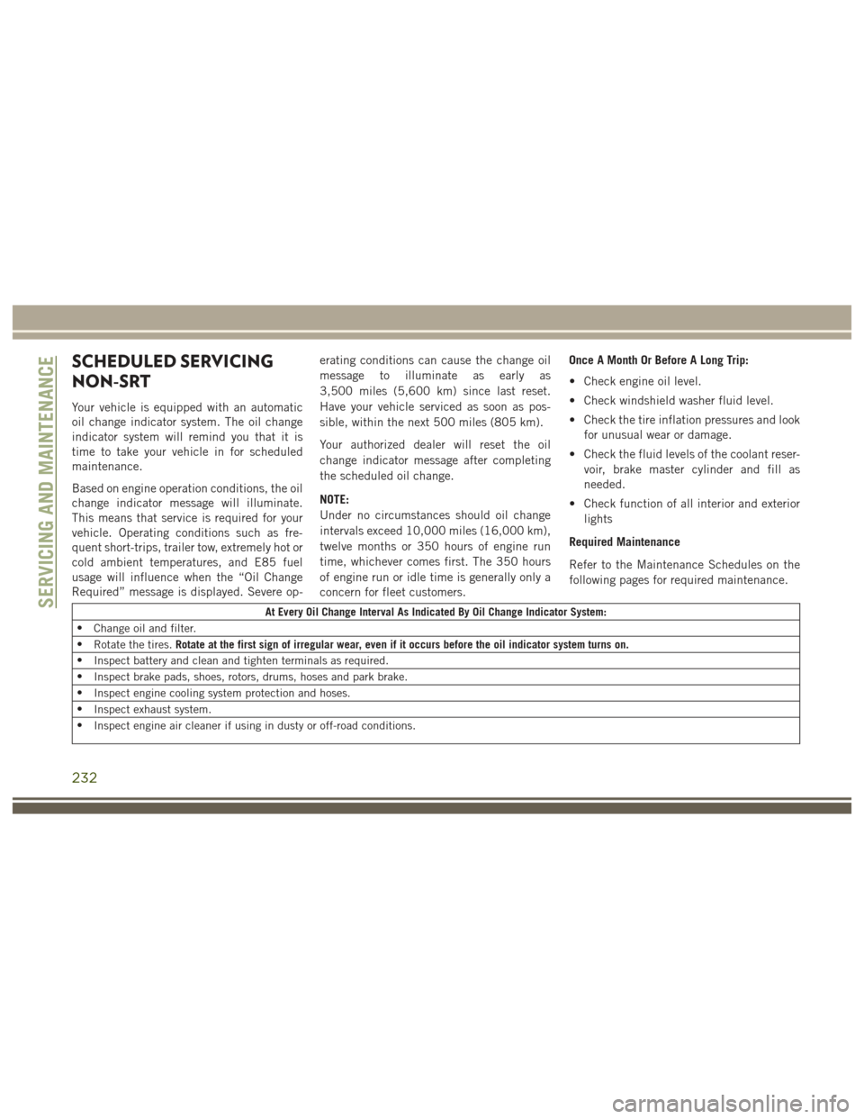
SCHEDULED SERVICING
NON-SRT
Your vehicle is equipped with an automatic
oil change indicator system. The oil change
indicator system will remind you that it is
time to take your vehicle in for scheduled
maintenance.
Based on engine operation conditions, the oil
change indicator message will illuminate.
This means that service is required for your
vehicle. Operating conditions such as fre-
quent short-trips, trailer tow, extremely hot or
cold ambient temperatures, and E85 fuel
usage will influence when the “Oil Change
Required” message is displayed. Severe op-erating conditions can cause the change oil
message to illuminate as early as
3,500 miles (5,600 km) since last reset.
Have your vehicle serviced as soon as pos-
sible, within the next 500 miles (805 km).
Your authorized dealer will reset the oil
change indicator message after completing
the scheduled oil change.
NOTE:
Under no circumstances should oil change
intervals exceed 10,000 miles (16,000 km),
twelve months or 350 hours of engine run
time, whichever comes first. The 350 hours
of engine run or idle time is generally only a
concern for fleet customers. Once A Month Or Before A Long Trip:
• Check engine oil level.
• Check windshield washer fluid level.
• Check the tire inflation pressures and look
for unusual wear or damage.
• Check the fluid levels of the coolant reser- voir, brake master cylinder and fill as
needed.
• Check function of all interior and exterior lights
Required Maintenance
Refer to the Maintenance Schedules on the
following pages for required maintenance.
At Every Oil Change Interval As Indicated By Oil Change Indicator System:
• Change oil and filter.
• Rotate the tires. Rotate at the first sign of irregular wear, even if it occurs before the oil indicator system turns on.
• Inspect battery and clean and tighten terminals as required.
• Inspect brake pads, shoes, rotors, drums, hoses and park brake.
• Inspect engine cooling system protection and hoses.
• Inspect exhaust system.
• Inspect engine air cleaner if using in dusty or off-road conditions.SERVICING AND MAINTENANCE
232
Page 237 of 372
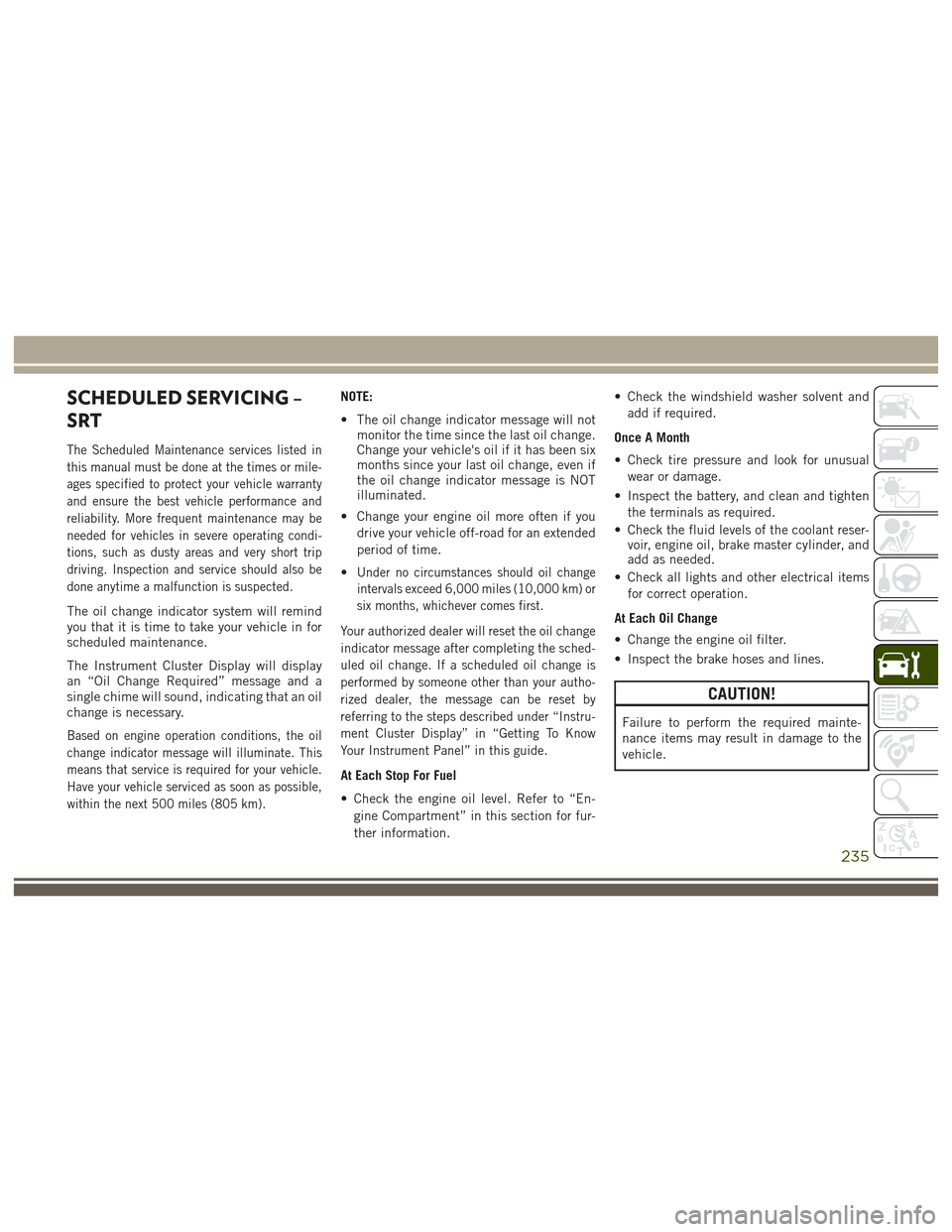
SCHEDULED SERVICING –
SRT
The Scheduled Maintenance services listed in
this manual must be done at the times or mile-
ages specified to protect your vehicle warranty
and ensure the best vehicle performance and
reliability. More frequent maintenance may be
needed for vehicles in severe operating condi-
tions, such as dusty areas and very short trip
driving. Inspection and service should also be
done anytime a malfunction is suspected.
The oil change indicator system will remind
you that it is time to take your vehicle in for
scheduled maintenance.
The Instrument Cluster Display will display
an “Oil Change Required” message and a
single chime will sound, indicating that an oil
change is necessary.
Based on engine operation conditions, the oil
change indicator message will illuminate. This
means that service is required for your vehicle.
Have your vehicle serviced as soon as possible,
within the next 500 miles (805 km).
NOTE:
• The oil change indicator message will notmonitor the time since the last oil change.
Change your vehicle's oil if it has been six
months since your last oil change, even if
the oil change indicator message is NOT
illuminated.
• Change your engine oil more often if you drive your vehicle off-road for an extended
period of time.
•
Under no circumstances should oil change
intervals exceed 6,000 miles (10,000 km) or
six months, whichever comes first.
Your authorized dealer will reset the oil change
indicator message after completing the sched-
uled oil change. If a scheduled oil change is
performed by someone other than your autho-
rized dealer, the message can be reset by
referring to the steps described under “Instru-
ment Cluster Display” in “Getting To Know
Your Instrument Panel” in this guide.
At Each Stop For Fuel
• Check the engine oil level. Refer to “En- gine Compartment” in this section for fur-
ther information. • Check the windshield washer solvent and
add if required.
Once A Month
• Check tire pressure and look for unusual wear or damage.
• Inspect the battery, and clean and tighten the terminals as required.
• Check the fluid levels of the coolant reser- voir, engine oil, brake master cylinder, and
add as needed.
• Check all lights and other electrical items for correct operation.
At Each Oil Change
• Change the engine oil filter.
• Inspect the brake hoses and lines.
CAUTION!
Failure to perform the required mainte-
nance items may result in damage to the
vehicle.
235