light JEEP GRAND CHEROKEE 2017 WK2 / 4.G Manual PDF
[x] Cancel search | Manufacturer: JEEP, Model Year: 2017, Model line: GRAND CHEROKEE, Model: JEEP GRAND CHEROKEE 2017 WK2 / 4.GPages: 372
Page 189 of 372
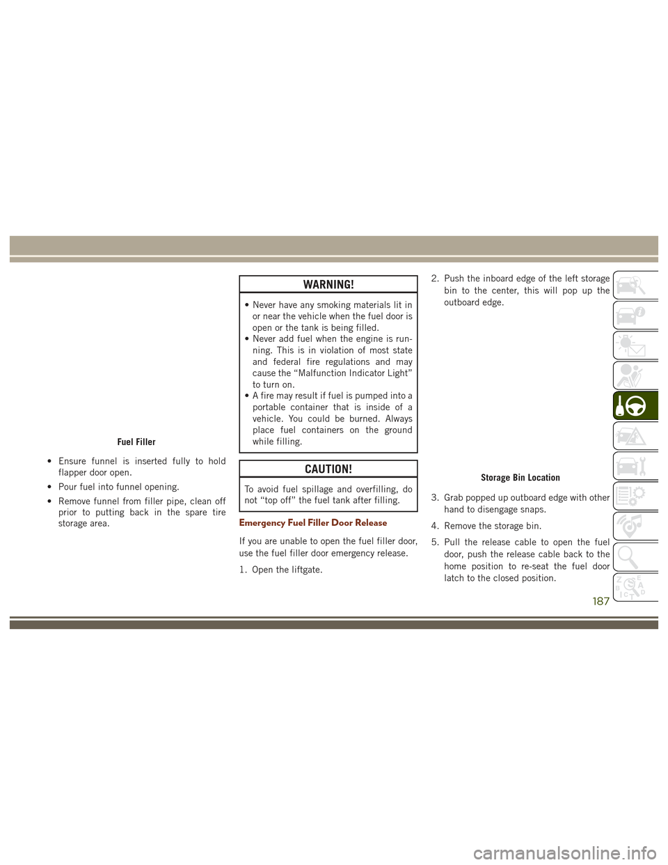
• Ensure funnel is inserted fully to holdflapper door open.
• Pour fuel into funnel opening.
• Remove funnel from filler pipe, clean off prior to putting back in the spare tire
storage area.
WARNING!
• Never have any smoking materials lit in
or near the vehicle when the fuel door is
open or the tank is being filled.
• Never add fuel when the engine is run-
ning. This is in violation of most state
and federal fire regulations and may
cause the “Malfunction Indicator Light”
to turn on.
• A fire may result if fuel is pumped into a
portable container that is inside of a
vehicle. You could be burned. Always
place fuel containers on the ground
while filling.
CAUTION!
To avoid fuel spillage and overfilling, do
not “top off” the fuel tank after filling.
Emergency Fuel Filler Door Release
If you are unable to open the fuel filler door,
use the fuel filler door emergency release.
1. Open the liftgate. 2. Push the inboard edge of the left storage
bin to the center, this will pop up the
outboard edge.
3. Grab popped up outboard edge with other hand to disengage snaps.
4. Remove the storage bin.
5. Pull the release cable to open the fuel door, push the release cable back to the
home position to re-seat the fuel door
latch to the closed position.
Fuel Filler
Storage Bin Location
187
Page 192 of 372
WARNING!
• Never have any smoking materials lit inor near the vehicle when the fuel door is
open or the tank is being filled.
• Never add fuel when the engine is run-
ning. This is in violation of most state
and federal fire regulations and may
cause the “Malfunction Indicator Light”
to turn on.
• A fire may result if fuel is pumped into a
portable container that is inside of a
vehicle. You could be burned. Always
place fuel containers on the ground
while filling.
CAUTION!
To avoid fuel spillage and overfilling, do
not “top off” the fuel tank after filling.
Avoid Using Contaminated Fuel
Fuel that is contaminated by water or dirt can
cause severe damage to the engine fuel sys-
tem. Proper maintenance of the engine fuel filter and fuel tank is essential. Refer to
“Dealer Service” in “Servicing And Mainte-
nance” for further information.
Bulk Fuel Storage — Diesel Fuel
If you store quantities of fuel, good mainte-
nance of the stored fuel is also essential. Fuel
contaminated with water will promote the
growth of “microbes.” These microbes form
“slime” that will clog the fuel filtration sys-
tem and lines. Drain condensation from the
supply tank and change the line filter on a
regular basis.
NOTE:
When a diesel engine is allowed to run out of
fuel, air is pulled into the fuel system.
If the vehicle will not start, refer to “Dealer
Service / Priming If The Engine Has Run Out
Of Fuel” in “Servicing And Maintenance” for
further information.
WARNING!
Do not open the high pressure fuel system
with the engine running. Engine operation
causes high fuel pressure. High pressure
WARNING!
fuel spray can cause serious injury or
death.
Diesel Exhaust Fluid
Your vehicle is equipped with a Selective
Catalytic Reduction system to meet the very
stringent diesel emissions standards re-
quired by the Environmental Protection
Agency.
The purpose of the SCR system is to reduce
levels of NOx (oxides of nitrogen emitted from
engines) that are harmful to our health and
the environment to a near-zero level. Small
quantities of Diesel Exhaust Fluid (DEF) is
injected into the exhaust upstream of a cata-
lyst where, when vaporized, it converts smog-
forming nitrogen oxides (NOx) into harmless
nitrogen (N2) and water vapor (H2O), two
natural components of the air we breathe.
You can operate with the comfort that your
vehicle is contributing to a cleaner, healthier
world environment for this and generations to
come.
STARTING AND OPERATING
190
Page 202 of 372
CAUTION!
age. Tow with all four wheels either ON
the ground, or OFF the ground (using a
vehicle trailer).
• Tow only in a forward direction. Towing
this vehicle backwards can cause severe
damage to the transfer case.
• The transmission must be in PARK for
recreational towing.
• Before recreational towing, perform the
procedure outlined under “Shifting into
NEUTRAL (N)” to be certain that the
transfer case is fully in NEUTRAL (N).
Otherwise, internal damage will result.
• Towing this vehicle in violation of the
above requirements can cause severe
transmission and/or transfer case dam-
age. Damage from improper towing is
not covered under the New Vehicle Lim-
ited Warranty.
• Do not use a bumper-mounted clamp-on
tow bar on your vehicle. The bumper
face bar will be damaged.
Shifting Into NEUTRAL (N)
WARNING!
You or others could be injured or killed if
you leave the vehicle unattended with the
transfer case in the NEUTRAL (N) position
without first fully engaging the parking
brake. The transfer case NEUTRAL (N)
position disengages both the front and rear
driveshafts from the powertrain and will
allow the vehicle to roll, even if the trans-
mission is in PARK. The parking brake
should always be applied when the driver
is not in the vehicle.
Use the following procedure to prepare your
vehicle for recreational towing.
CAUTION!
It is necessary to follow these steps to be
certain that the transfer case is fully in
NEUTRAL (N) before recreational towing
to prevent damage to internal parts. 1. Bring the vehicle to a complete stop, with
the engine running.
2. Press and hold the brake pedal.
3. Shift the transmission into NEUTRAL.
4. If vehicle is equipped with Quadra-Lift air suspension, ensure the vehicle is set to
Normal Ride Height.
5. Using a ballpoint pen or similar object, push and hold the recessed transfer case
NEUTRAL (N) button (located by the se-
lector switch) for four seconds. The light
behind the N symbol will blink, indicating
shift in progress. The light will stop blink-
ing (stay on solid) when the shift to NEU-
TRAL (N) is complete. A “FOUR WHEEL
DRIVE SYSTEM IN NEUTRAL” message
will appear in the instrument cluster.
STARTING AND OPERATING
200
Page 203 of 372
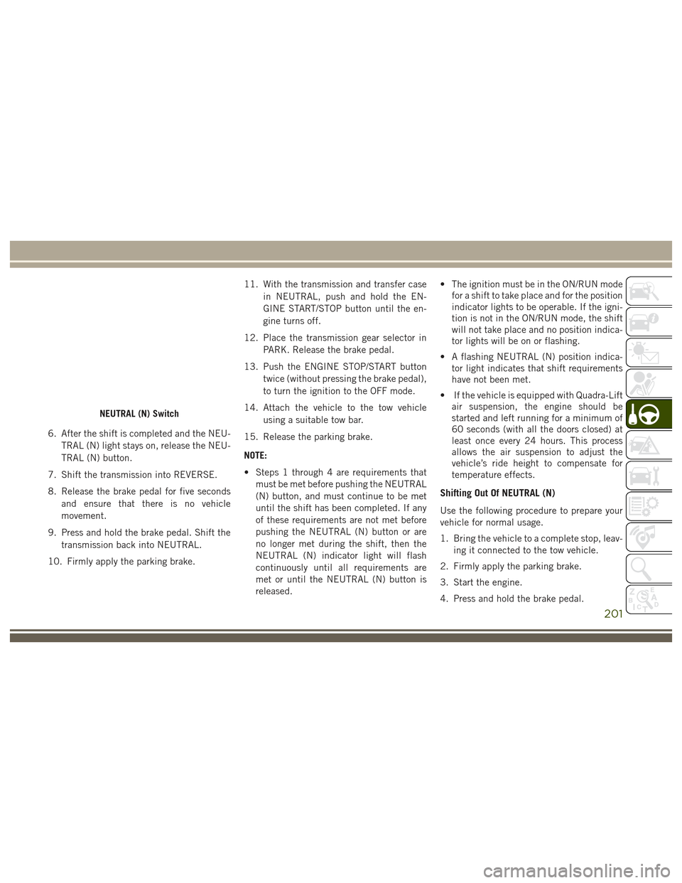
6. After the shift is completed and the NEU-TRAL (N) light stays on, release the NEU-
TRAL (N) button.
7. Shift the transmission into REVERSE.
8. Release the brake pedal for five seconds and ensure that there is no vehicle
movement.
9. Press and hold the brake pedal. Shift the transmission back into NEUTRAL.
10. Firmly apply the parking brake. 11. With the transmission and transfer case
in NEUTRAL, push and hold the EN-
GINE START/STOP button until the en-
gine turns off.
12. Place the transmission gear selector in PARK. Release the brake pedal.
13. Push the ENGINE STOP/START button twice (without pressing the brake pedal),
to turn the ignition to the OFF mode.
14. Attach the vehicle to the tow vehicle using a suitable tow bar.
15. Release the parking brake.
NOTE:
• Steps 1 through 4 are requirements that must be met before pushing the NEUTRAL
(N) button, and must continue to be met
until the shift has been completed. If any
of these requirements are not met before
pushing the NEUTRAL (N) button or are
no longer met during the shift, then the
NEUTRAL (N) indicator light will flash
continuously until all requirements are
met or until the NEUTRAL (N) button is
released. • The ignition must be in the ON/RUN mode
for a shift to take place and for the position
indicator lights to be operable. If the igni-
tion is not in the ON/RUN mode, the shift
will not take place and no position indica-
tor lights will be on or flashing.
• A flashing NEUTRAL (N) position indica- tor light indicates that shift requirements
have not been met.
• If the vehicle is equipped with Quadra-Lift air suspension, the engine should be
started and left running for a minimum of
60 seconds (with all the doors closed) at
least once every 24 hours. This process
allows the air suspension to adjust the
vehicle’s ride height to compensate for
temperature effects.
Shifting Out Of NEUTRAL (N)
Use the following procedure to prepare your
vehicle for normal usage.
1. Bring the vehicle to a complete stop, leav-
ing it connected to the tow vehicle.
2. Firmly apply the parking brake.
3. Start the engine.
4. Press and hold the brake pedal.
NEUTRAL (N) Switch
201
Page 204 of 372
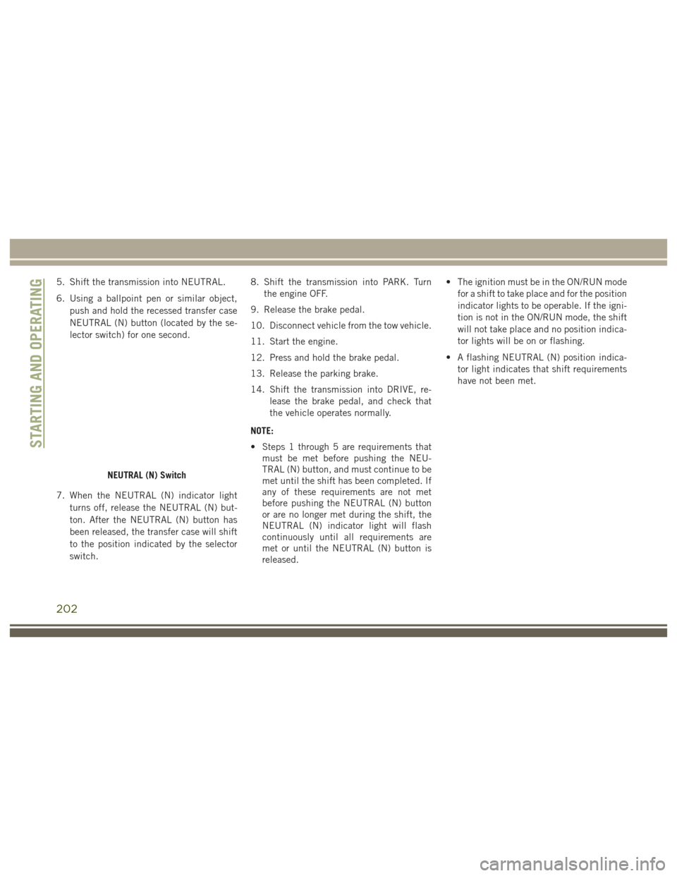
5. Shift the transmission into NEUTRAL.
6. Using a ballpoint pen or similar object,push and hold the recessed transfer case
NEUTRAL (N) button (located by the se-
lector switch) for one second.
7. When the NEUTRAL (N) indicator light turns off, release the NEUTRAL (N) but-
ton. After the NEUTRAL (N) button has
been released, the transfer case will shift
to the position indicated by the selector
switch. 8. Shift the transmission into PARK. Turn
the engine OFF.
9. Release the brake pedal.
10. Disconnect vehicle from the tow vehicle.
11. Start the engine.
12. Press and hold the brake pedal.
13. Release the parking brake.
14. Shift the transmission into DRIVE, re- lease the brake pedal, and check that
the vehicle operates normally.
NOTE:
• Steps 1 through 5 are requirements that must be met before pushing the NEU-
TRAL (N) button, and must continue to be
met until the shift has been completed. If
any of these requirements are not met
before pushing the NEUTRAL (N) button
or are no longer met during the shift, the
NEUTRAL (N) indicator light will flash
continuously until all requirements are
met or until the NEUTRAL (N) button is
released. • The ignition must be in the ON/RUN mode
for a shift to take place and for the position
indicator lights to be operable. If the igni-
tion is not in the ON/RUN mode, the shift
will not take place and no position indica-
tor lights will be on or flashing.
• A flashing NEUTRAL (N) position indica- tor light indicates that shift requirements
have not been met.
NEUTRAL (N) Switch
STARTING AND OPERATING
202
Page 210 of 372
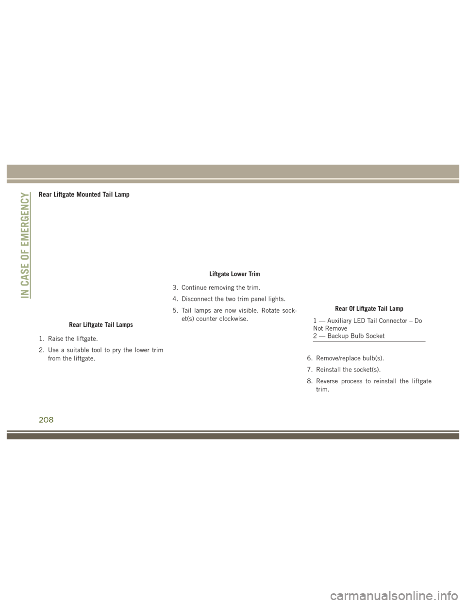
Rear Liftgate Mounted Tail Lamp
1. Raise the liftgate.
2. Use a suitable tool to pry the lower trimfrom the liftgate. 3. Continue removing the trim.
4. Disconnect the two trim panel lights.
5. Tail lamps are now visible. Rotate sock-
et(s) counter clockwise.
6. Remove/replace bulb(s).
7. Reinstall the socket(s).
8. Reverse process to reinstall the liftgatetrim.
Rear Liftgate Tail Lamps
Liftgate Lower Trim
Rear Of Liftgate Tail Lamp
1 — Auxiliary LED Tail Connector – Do
Not Remove
2 — Backup Bulb Socket
IN CASE OF EMERGENCY
208
Page 212 of 372
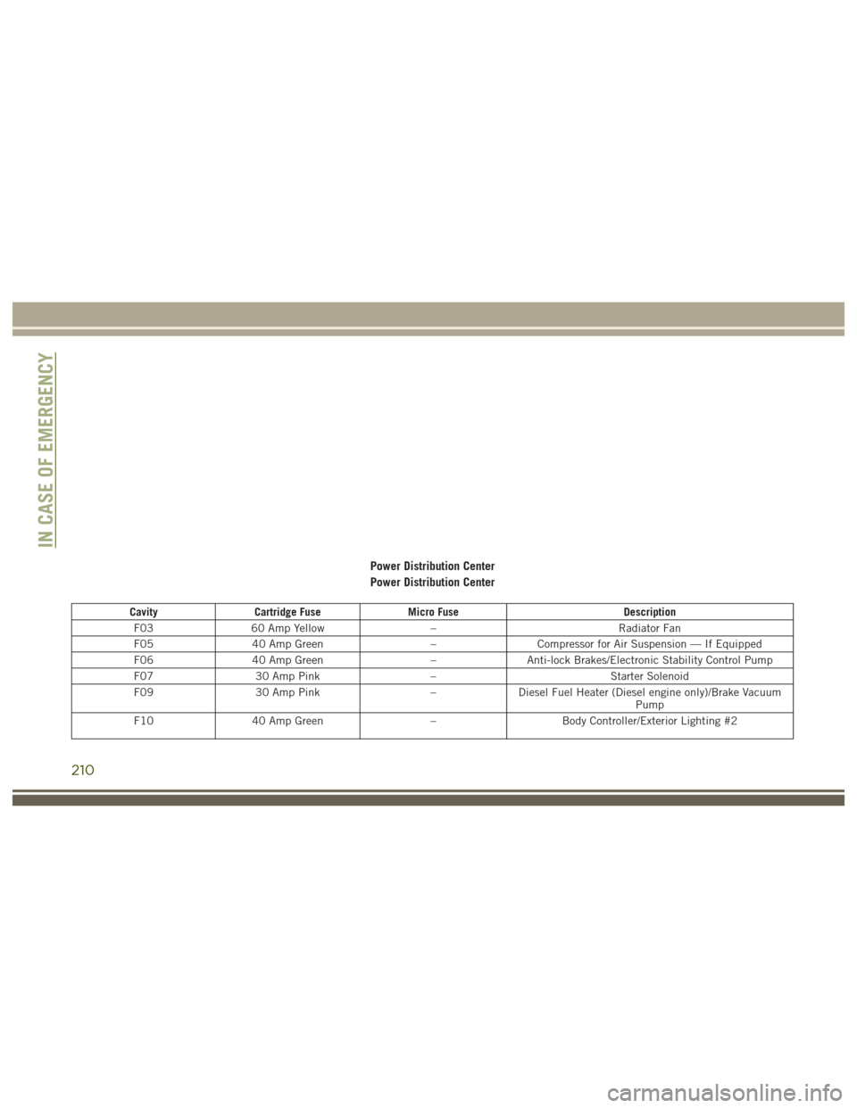
CavityCartridge Fuse Micro Fuse Description
F03 60 Amp Yellow – Radiator Fan
F05 40 Amp Green –Compressor for Air Suspension — If Equipped
F06 40 Amp Green –Anti-lock Brakes/Electronic Stability Control Pump
F07 30 Amp Pink – Starter Solenoid
F09 30 Amp Pink –Diesel Fuel Heater (Diesel engine only)/Brake Vacuum
Pump
F10 40 Amp Green –Body Controller/Exterior Lighting #2
Power Distribution Center
Power Distribution Center
IN CASE OF EMERGENCY
210
Page 213 of 372
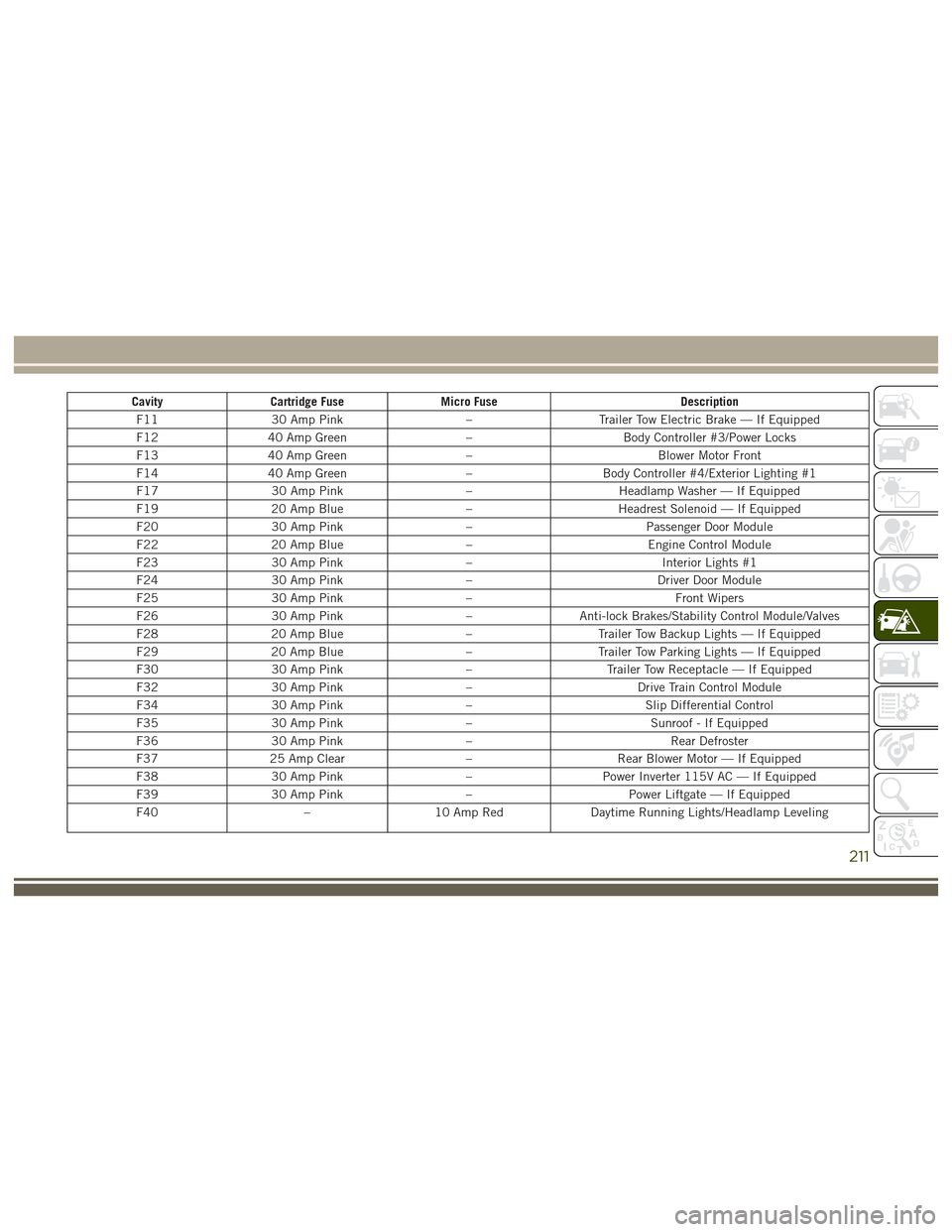
CavityCartridge Fuse Micro Fuse Description
F11 30 Amp Pink –Trailer Tow Electric Brake — If Equipped
F12 40 Amp Green –Body Controller #3/Power Locks
F13 40 Amp Green –Blower Motor Front
F14 40 Amp Green –Body Controller #4/Exterior Lighting #1
F17 30 Amp Pink –Headlamp Washer — If Equipped
F19 20 Amp Blue –Headrest Solenoid — If Equipped
F20 30 Amp Pink –Passenger Door Module
F22 20 Amp Blue –Engine Control Module
F23 30 Amp Pink – Interior Lights #1
F24 30 Amp Pink –Driver Door Module
F25 30 Amp Pink – Front Wipers
F26 30 Amp Pink –Anti-lock Brakes/Stability Control Module/Valves
F28 20 Amp Blue –Trailer Tow Backup Lights — If Equipped
F29 20 Amp Blue –Trailer Tow Parking Lights — If Equipped
F30 30 Amp Pink –Trailer Tow Receptacle — If Equipped
F32 30 Amp Pink –Drive Train Control Module
F34 30 Amp Pink –Slip Differential Control
F35 30 Amp Pink –Sunroof - If Equipped
F36 30 Amp Pink – Rear Defroster
F37 25 Amp Clear –Rear Blower Motor — If Equipped
F38 30 Amp Pink –Power Inverter 115V AC — If Equipped
F39 30 Amp Pink –Power Liftgate — If Equipped
F40 –10 Amp Red Daytime Running Lights/Headlamp Leveling
211
Page 214 of 372
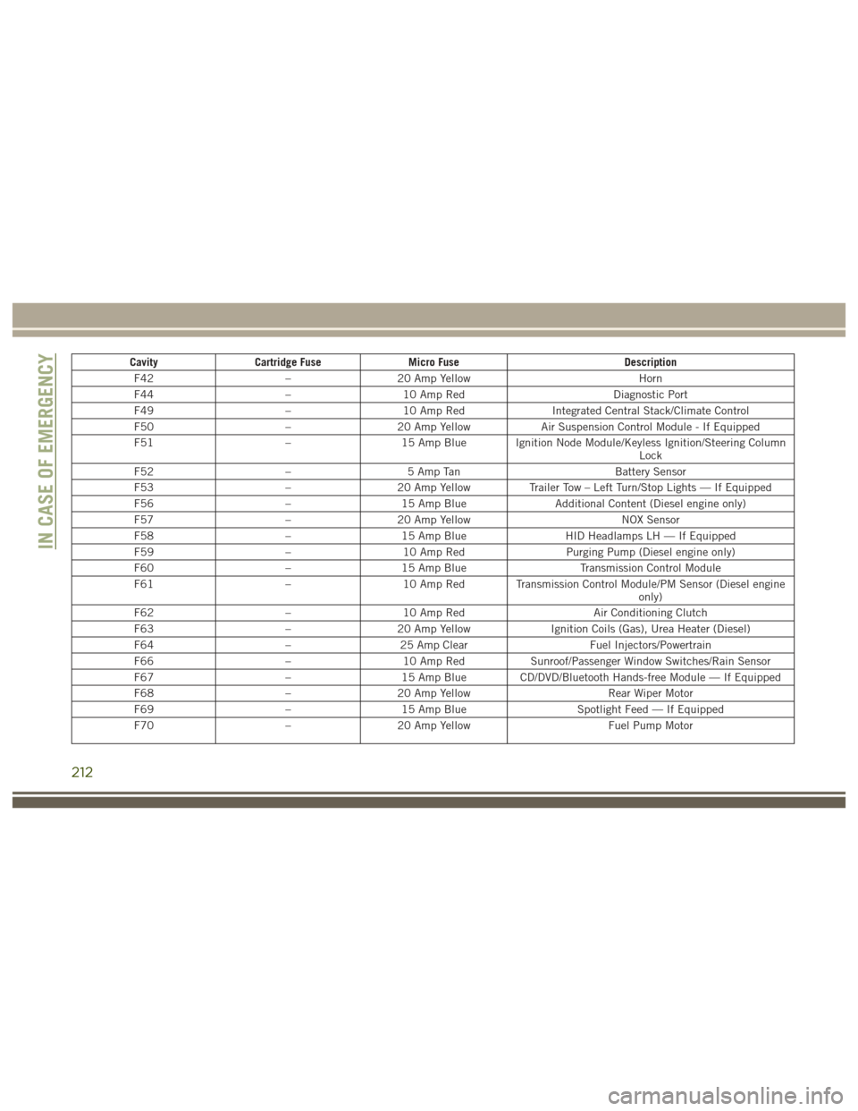
CavityCartridge Fuse Micro Fuse Description
F42 –20 Amp Yellow Horn
F44 –10 Amp Red Diagnostic Port
F49 –10 Amp Red Integrated Central Stack/Climate Control
F50 –20 Amp Yellow Air Suspension Control Module - If Equipped
F51 –15 Amp Blue Ignition Node Module/Keyless Ignition/Steering Column
Lock
F52 –5 Amp Tan Battery Sensor
F53 –20 Amp Yellow Trailer Tow – Left Turn/Stop Lights — If Equipped
F56 –15 Amp Blue Additional Content (Diesel engine only)
F57 –20 Amp Yellow NOX Sensor
F58 –15 Amp Blue HID Headlamps LH — If Equipped
F59 –10 Amp Red Purging Pump (Diesel engine only)
F60 –15 Amp Blue Transmission Control Module
F61 –10 Amp Red Transmission Control Module/PM Sensor (Diesel engine
only)
F62 –10 Amp Red Air Conditioning Clutch
F63 –20 Amp Yellow Ignition Coils (Gas), Urea Heater (Diesel)
F64 –25 Amp Clear Fuel Injectors/Powertrain
F66 –10 Amp Red Sunroof/Passenger Window Switches/Rain Sensor
F67 –15 Amp Blue CD/DVD/Bluetooth Hands-free Module — If Equipped
F68 –20 Amp Yellow Rear Wiper Motor
F69 –15 Amp Blue Spotlight Feed — If Equipped
F70 –20 Amp Yellow Fuel Pump Motor
IN CASE OF EMERGENCY
212
Page 215 of 372
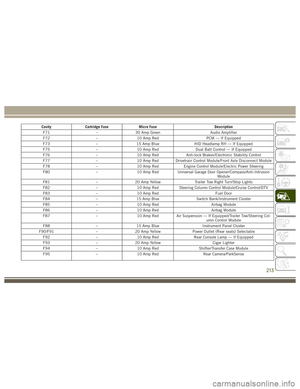
CavityCartridge Fuse Micro Fuse Description
F71 –30 Amp Green Audio Amplifier
F72 –10 Amp Red PCM — If Equipped
F73 –15 Amp Blue HID Headlamp RH — If Equipped
F75 –10 Amp Red Dual Batt Control — If Equipped
F76 –10 Amp Red Anti-lock Brakes/Electronic Stability Control
F77 –10 Amp Red Drivetrain Control Module/Front Axle Disconnect Module
F78 –10 Amp Red Engine Control Module/Electric Power Steering
F80 –10 Amp Red Universal Garage Door Opener/Compass/Anti-Intrusion
Module
F81 –20 Amp Yellow Trailer Tow Right Turn/Stop Lights
F82 –10 Amp Red Steering Column Control Module/Cruise Control/DTV
F83 –10 Amp Red Fuel Door
F84 –15 Amp Blue Switch Bank/Instrument Cluster
F85 –10 Amp Red Airbag Module
F86 –10 Amp Red Airbag Module
F87 –10 Amp Red Air Suspension — If Equipped/Trailer Tow/Steering Col-
umn Control Module
F88 –15 Amp Blue Instrument Panel Cluster
F90/F91 –20 Amp Yellow Power Outlet (Rear seats) Selectable
F92 –10 Amp Red Rear Console Lamp — If Equipped
F93 –20 Amp Yellow Cigar Lighter
F94 –10 Amp Red Shifter/Transfer Case Module
F95 –10 Amp Red Rear Camera/ParkSense
213