JEEP GRAND CHEROKEE 2018 Owner handbook (in English)
Manufacturer: JEEP, Model Year: 2018, Model line: GRAND CHEROKEE, Model: JEEP GRAND CHEROKEE 2018Pages: 368, PDF Size: 5.72 MB
Page 251 of 368
WARNING!
You can be badly injured working on or
around a motor vehicle. Only do service
work for which you have the knowledge
and the proper equipment. If you have any
doubt about your ability to perform a ser-
vice job, take your vehicle to a competent
mechanic.
Air Conditioner Maintenance
For best possible performance, your air con-
ditioner should be checked and serviced by
an authorized dealer at the start of each warm
season. This service should include cleaning
of the condenser fins and a performance test.
Drive belt tension should also be checked at
this time.
WARNING!
• Use only refrigerants and compressor
lubricants approved by the manufac-
turer for your air conditioning system.
Some unapproved refrigerants are flam-
WARNING!
mable and can explode, injuring you.
Other unapproved refrigerants or lubri-
cants can cause the system to fail, re-
quiring costly repairs. Refer to Warranty
Information Book, for further warranty
information.
• The air conditioning system contains re-
frigerant under high pressure. To avoid
risk of personal injury or damage to the
system, adding refrigerant or any repair
requiring lines to be disconnected
should be done by an experienced tech-
nician.
CAUTION!
Do not use chemical flushes in your air
conditioning system as the chemicals can
damage your air conditioning components.
Such damage is not covered by the New
Vehicle Limited Warranty.
Air Conditioning Filter Replacement (A/C Air
Filter)
Refer to “Scheduled Servicing” in this sec-
tion for the proper maintenance intervals.
WARNING!
Do not remove the cabin air filter while the
vehicle is running, or while the ignition is
in the ACC or ON/RUN mode. With the
cabin air filter removed and the blower
operating, the blower can contact hands
and may propel dirt and debris into your
eyes, resulting in personal injury.
The A/C air filter is located in the fresh air
inlet behind the glove compartment. Perform
the following procedure to replace the filter:
1. Open the glove compartment and remove
all contents.
249
Page 252 of 368
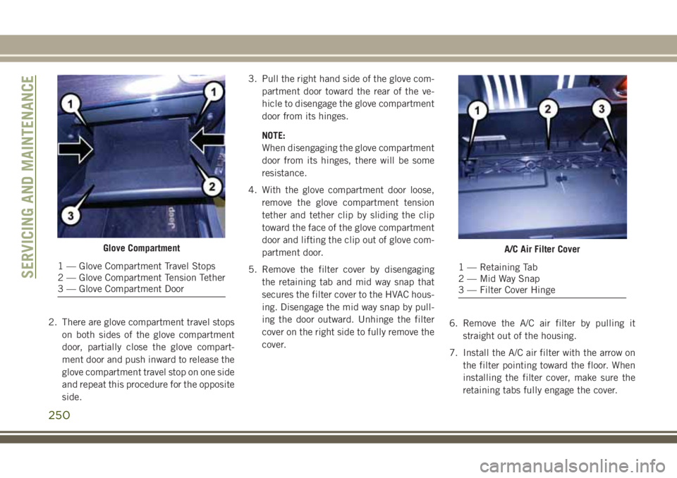
2. There are glove compartment travel stops
on both sides of the glove compartment
door, partially close the glove compart-
ment door and push inward to release the
glove compartment travel stop on one side
and repeat this procedure for the opposite
side.3. Pull the right hand side of the glove com-
partment door toward the rear of the ve-
hicle to disengage the glove compartment
door from its hinges.
NOTE:
When disengaging the glove compartment
door from its hinges, there will be some
resistance.
4. With the glove compartment door loose,
remove the glove compartment tension
tether and tether clip by sliding the clip
toward the face of the glove compartment
door and lifting the clip out of glove com-
partment door.
5. Remove the filter cover by disengaging
the retaining tab and mid way snap that
secures the filter cover to the HVAC hous-
ing. Disengage the mid way snap by pull-
ing the door outward. Unhinge the filter
cover on the right side to fully remove the
cover.6. Remove the A/C air filter by pulling it
straight out of the housing.
7. Install the A/C air filter with the arrow on
the filter pointing toward the floor. When
installing the filter cover, make sure the
retaining tabs fully engage the cover.
Glove Compartment
1 — Glove Compartment Travel Stops
2 — Glove Compartment Tension Tether
3 — Glove Compartment Door
A/C Air Filter Cover
1 — Retaining Tab
2 — Mid Way Snap
3 — Filter Cover HingeSERVICING AND MAINTENANCE
250
Page 253 of 368
CAUTION!
The cabin air filter is identified with an
arrow to indicate airflow direction through
the filter. Failure to properly install the
filter will result in the need to replace it
more often.
8. Reinstall the glove compartment door on
the door hinge and reattach the tension
tether by inserting the tether clip in the
glove compartment and sliding the clip
away from the face of the glove compart-
ment door.
9. Push the door to the near closed position
to reengage the glove compartment travel
stops.
NOTE:
Ensure the glove compartment door
hinges and glove compartment travel
stops are fully engaged.
Windshield Wiper Blades
Clean the rubber edges of the wiper blades
and the windshield periodically with a sponge
or soft cloth and a mild nonabrasive cleaner.
This will remove accumulations of salt or road
film.
Operation of the wipers on dry glass for long
periods may cause deterioration of the wiper
blades. Always use washer fluid when using
the wipers to remove salt or dirt from a dry
windshield.
Avoid using the wiper blades to remove frost
or ice from the windshield. Keep the blade
rubber out of contact with petroleum prod-
ucts such as engine oil, gasoline, etc.
NOTE:
Life expectancy of wiper blades varies de-
pending on geographical area and frequency
of use. Poor performance of blades may be
present with chattering, marks, water lines or
wet spots. If any of these conditions are
present, clean the wiper blades or replace as
necessary.The wiper blades and wiper arms should be
inspected periodically, not just when wiper
performance problems are experienced. This
inspection should include the following
points:
• Wear Or Uneven Edges
• Foreign Material
• Hardening Or Cracking
• Deformation Or Fatigue
If a wiper blade or wiper arm is damaged,
replace the affected wiper arm or blade with a
new unit. Do not attempt to repair a wiper
arm or blade that is damaged.
Front Wiper Blade Removal/Installation
CAUTION!
Do not allow the wiper arm to spring back
against the glass without the wiper blade
in place or the glass may be damaged.
251
Page 254 of 368
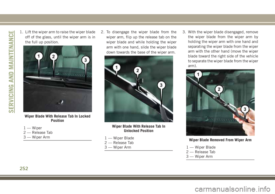
1. Lift the wiper arm to raise the wiper blade
off of the glass, until the wiper arm is in
the full up position.2. To disengage the wiper blade from the
wiper arm, flip up the release tab on the
wiper blade and while holding the wiper
arm with one hand, slide the wiper blade
down towards the base of the wiper arm.3. With the wiper blade disengaged, remove
the wiper blade from the wiper arm by
holding the wiper arm with one hand and
separating the wiper blade from the wiper
arm with the other hand (move the wiper
blade toward the right side of the vehicle
to separate the wiper blade from the wiper
arm).
Wiper Blade With Release Tab In Locked
Position
1 — Wiper
2 — Release Tab
3 — Wiper ArmWiper Blade With Release Tab In
Unlocked Position
1 — Wiper Blade
2 — Release Tab
3 — Wiper ArmWiper Blade Removed From Wiper Arm
1 — Wiper Blade
2 — Release Tab
3 — Wiper Arm
SERVICING AND MAINTENANCE
252
Page 255 of 368
4. Gently lower the wiper arm onto the glass.
Installing The Front Wipers
1. Lift the wiper arm off of the glass, until
the wiper arm is in the full up position.
2. Position the wiper blade near the hook on
the tip of the wiper arm with the wiper
release tab open and the blade side of the
wiper facing up and away from the
windshield.
3. Insert the hook on the tip of the arm
through the opening in the wiper blade
under the release tab.
4. Slide the wiper blade up into the hook on
the wiper arm and rotate the wiper blade
until it is flush against the wiper arm. Fold
down the latch release tab and snap it into
its locked position. Latch engagement will
be accompanied by an audible click.
5. Gently lower the wiper blade onto the
glass.
Rear Wiper Blade Removal/Installation
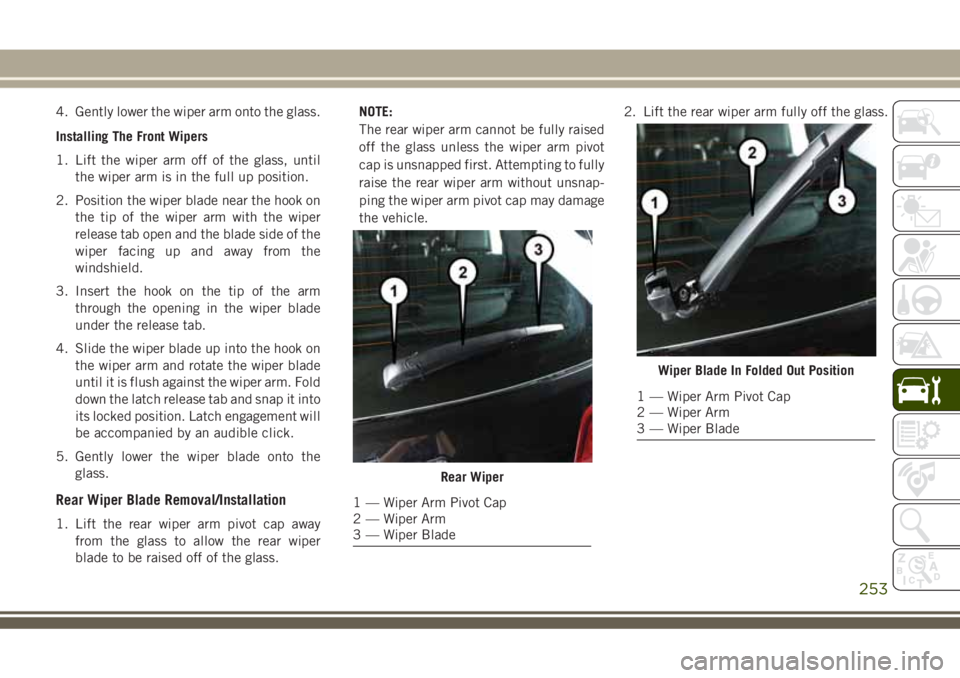
1. Lift the rear wiper arm pivot cap away
from the glass to allow the rear wiper
blade to be raised off of the glass.NOTE:
The rear wiper arm cannot be fully raised
off the glass unless the wiper arm pivot
cap is unsnapped first. Attempting to fully
raise the rear wiper arm without unsnap-
ping the wiper arm pivot cap may damage
the vehicle.2. Lift the rear wiper arm fully off the glass.
Rear Wiper
1 — Wiper Arm Pivot Cap
2 — Wiper Arm
3 — Wiper Blade
Wiper Blade In Folded Out Position
1 — Wiper Arm Pivot Cap
2 — Wiper Arm
3 — Wiper Blade
253
Page 256 of 368
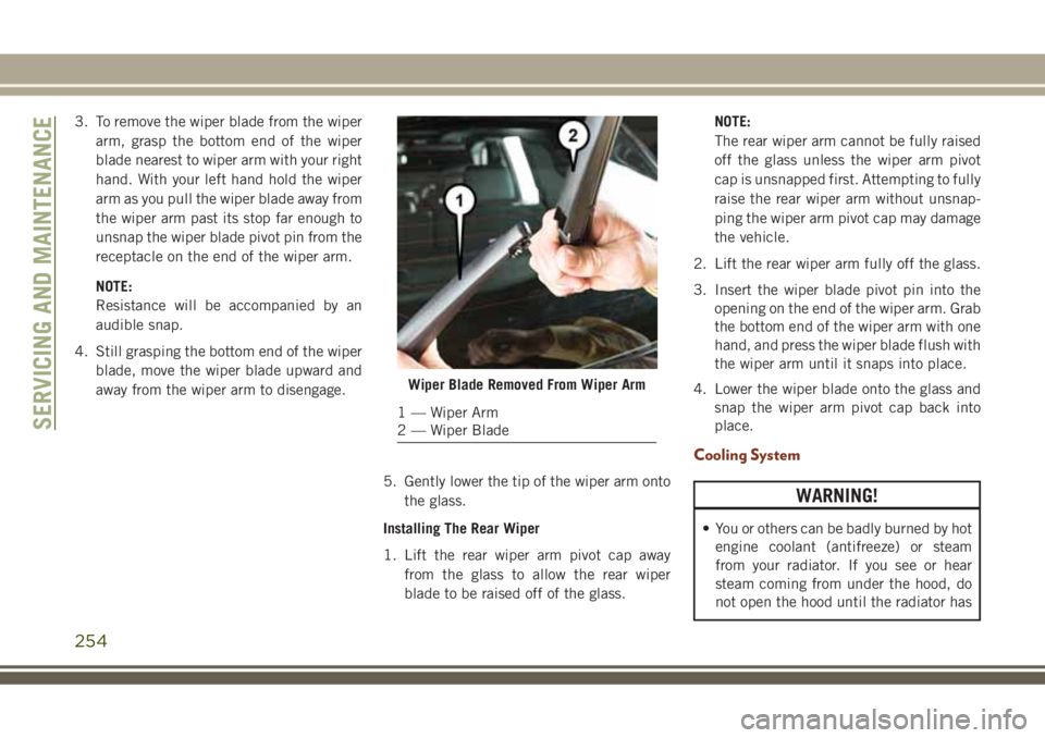
3. To remove the wiper blade from the wiper
arm, grasp the bottom end of the wiper
blade nearest to wiper arm with your right
hand. With your left hand hold the wiper
arm as you pull the wiper blade away from
the wiper arm past its stop far enough to
unsnap the wiper blade pivot pin from the
receptacle on the end of the wiper arm.
NOTE:
Resistance will be accompanied by an
audible snap.
4. Still grasping the bottom end of the wiper
blade, move the wiper blade upward and
away from the wiper arm to disengage.
5. Gently lower the tip of the wiper arm onto
the glass.
Installing The Rear Wiper
1. Lift the rear wiper arm pivot cap away
from the glass to allow the rear wiper
blade to be raised off of the glass.NOTE:
The rear wiper arm cannot be fully raised
off the glass unless the wiper arm pivot
cap is unsnapped first. Attempting to fully
raise the rear wiper arm without unsnap-
ping the wiper arm pivot cap may damage
the vehicle.
2. Lift the rear wiper arm fully off the glass.
3. Insert the wiper blade pivot pin into the
opening on the end of the wiper arm. Grab
the bottom end of the wiper arm with one
hand, and press the wiper blade flush with
the wiper arm until it snaps into place.
4. Lower the wiper blade onto the glass and
snap the wiper arm pivot cap back into
place.
Cooling System
WARNING!
• You or others can be badly burned by hot
engine coolant (antifreeze) or steam
from your radiator. If you see or hear
steam coming from under the hood, do
not open the hood until the radiator has
Wiper Blade Removed From Wiper Arm
1 — Wiper Arm
2 — Wiper BladeSERVICING AND MAINTENANCE
254
Page 257 of 368
WARNING!
had time to cool. Never open a cooling
system pressure cap when the radiator
or coolant bottle is hot.
• Keep hands, tools, clothing, and jewelry
away from the radiator cooling fan when
the hood is raised. The fan starts auto-
matically and may start at any time,
whether the engine is running or not.
• When working near the radiator cooling
fan, disconnect the fan motor lead or
turn the ignition to the OFF mode. The
fan is temperature controlled and can
start at any time the ignition is in the ON
mode.
Engine Coolant Checks
Check the engine coolant (antifreeze) protec-
tion every 12 months (before the onset of
freezing weather, where applicable). If the
engine coolant (antifreeze) is dirty, the sys-
tem should be drained, flushed, and refilled
with fresh OAT coolant (conforming to
MS.90032) by an authorized dealer. Check
the front of the A/C condenser for any accu-mulation of bugs, leaves, etc. If dirty, clean
by gently spraying water from a garden hose
vertically down the face of the condenser.
Check the engine cooling system hoses for
brittle rubber, cracking, tears, cuts, and
tightness of the connection at the coolant
recovery bottle and radiator. Inspect the en-
tire system for leaks. DO NOT REMOVE THE
COOLANT PRESSURE CAP WHEN THE
COOLING SYSTEM IS HOT.
RAISING THE VEHICLE
In the case where it is necessary to raise the
vehicle, go to an authorized dealer or service
station.
TIRES
Tires — General Information
Tire Pressure
Proper tire inflation pressure is essential to
the safe and satisfactory operation of your
vehicle. Four primary areas are affected by
improper tire pressure:
• Safety and Vehicle Stability• Economy
• Tread Wear
• Ride Comfort
Safety
WARNING!
• Improperly inflated tires are dangerous
and can cause collisions.
• Underinflation increases tire flexing and
can result in overheating and tire failure.
• Overinflation reduces a tire's ability to
cushion shock. Objects on the road and
chuckholes can cause damage that re-
sult in tire failure.
• Overinflated or underinflated tires can
affect vehicle handling and can fail sud-
denly, resulting in loss of vehicle control.
• Unequal tire pressures can cause steer-
ing problems. You could lose control of
your vehicle.
• Unequal tire pressures from one side of
the vehicle to the other can cause the
vehicle to drift to the right or left.
255
Page 258 of 368
WARNING!
• Always drive with each tire inflated to
the recommended cold tire inflation
pressure.
Both under-inflation and over-inflation affect
the stability of the vehicle and can produce a
feeling of sluggish response or over respon-
siveness in the steering.
NOTE:
• Unequal tire pressures from side to side
may cause erratic and unpredictable steer-
ing response.
• Unequal tire pressure from side to side may
cause the vehicle to drift left or right.
Fuel Economy
Underinflated tires will increase tire rolling
resistance resulting in higher fuel consump-
tion.
Tread Wear
Improper cold tire inflation pressures can
cause abnormal wear patterns and reduced
tread life, resulting in the need for earlier tire
replacement.Ride Comfort And Vehicle Stability
Proper tire inflation contributes to a comfort-
able ride. Over-inflation produces a jarring
and uncomfortable ride.
Tire Inflation Pressures
The proper cold tire inflation pressure is
listed on the left side B-Pillar or rear edge of
the passenger door.
At least once a month:
• Check and adjust tire pressure with a good
quality pocket-type pressure gauge. Do not
make a visual judgement when determining
proper inflation. Tires may look properly
inflated even when they are under-inflated.
• Inspect tires for signs of tire wear or visible
damage.
CAUTION!
After inspecting or adjusting the tire pres-
sure, always reinstall the valve stem cap.
This will prevent moisture and dirt from
entering the valve stem, which could dam-
age the valve stem.Inflation pressures specified on the placard
are always “cold tire inflation pressure”. Cold
tire inflation pressure is defined as the tire
pressure after the vehicle has not been driven
for at least three hours, or driven less than
1 mile (1.6 km) after sitting for a minimum of
three hours. The cold tire inflation pressure
must not exceed the maximum inflation pres-
sure molded into the tire sidewall.
Check tire pressures more often if subject to
a wide range of outdoor temperatures, as tire
pressures vary with temperature changes.
Tire pressures change by approximately 1 psi
(7 kPa) per 12°F (7°C) of air temperature
change. Keep this in mind when checking
tire pressure inside a garage, especially in the
Winter.
Example: If garage temperature = 68°F
(20°C) and the outside temperature = 32°F
(0°C) then the cold tire inflation pressure
should be increased by 3 psi (21 kPa), which
equals 1 psi (7 kPa) for every 12°F (7°C) for
this outside temperature condition.
SERVICING AND MAINTENANCE
256
Page 259 of 368
Tire pressure may increase from 2 to 6 psi
(13 to 40 kPa) during operation. DO NOT
reduce this normal pressure build up or your
tire pressure will be too low.
Tire Pressures For High Speed Operation
The manufacturer advocates driving at safe
speeds and within posted speed limits. Where
speed limits or conditions are such that the
vehicle can be driven at high speeds, maintain-
ing correct tire inflation pressure is very impor-
tant. Increased tire pressure and reduced ve-
hicle loading may be required for high-speed
vehicle operation. Refer to an authorized tire
dealer or original equipment vehicle dealer for
recommended safe operating speeds, loading
and cold tire inflation pressures.
WARNING!
High speed driving with your vehicle under
maximum load is dangerous. The added
strain on your tires could cause them to
fail. You could have a serious collision. Do
not drive a vehicle loaded to the maximum
capacity at continuous speeds above
75 mph (120 km/h).
Radial Ply Tires
WARNING!
Combining radial ply tires with other types
of tires on your vehicle will cause your
vehicle to handle poorly. The instability
could cause a collision. Always use radial
ply tires in sets of four. Never combine
them with other types of tires.
Tire Repair
If your tire becomes damaged, it may be
repaired if it meets the following criteria:
• The tire has not been driven on when flat.
• The damage is only on the tread section of
your tire (sidewall damage is not repair-
able).
• The puncture is no greater thana¼ofan
inch (6 mm).
Consult an authorized tire dealer for tire re-
pairs and additional information.Damaged Run Flat tires, or Run Flat tires that
have experienced a loss of pressure should be
replaced immediately with another Run Flat
tire of identical size and service description
(Load Index and Speed Symbol).
Run Flat Tires — If Equipped
Run Flat tires allow you the capability to drive
50 miles (80 km) at 50 mph (80 km/h) after
a rapid loss of inflation pressure. This rapid
loss of inflation is referred to as the Run Flat
mode. A Run Flat mode occurs when the tire
inflation pressure is of/or below 14 psi
(96 kPa). Once a Run Flat tire reaches the
run flat mode it has limited driving capabili-
ties and needs to be replaced immediately. A
Run Flat tire is not repairable.
It is not recommended driving a vehicle
loaded at full capacity or to tow a trailer while
a tire is in the run flat mode.
See the tire pressure monitoring section for
more information.
257
Page 260 of 368
Tire Spinning
When stuck in mud, sand, snow, or ice con-
ditions, do not spin your vehicle's wheels
above 30 mph (48 km/h) or for longer than
30 seconds continuously without stopping.
Refer to “Freeing A Stuck Vehicle” in “In
Case Of Emergency” for further information.
WARNING!
Fast spinning tires can be dangerous.
Forces generated by excessive wheel
speeds may cause tire damage or failure. A
tire could explode and injure someone. Do
not spin your vehicle's wheels faster than
30 mph (48 km/h) for more than 30 sec-
onds continuously when you are stuck,
and do not let anyone near a spinning
wheel, no matter what the speed.
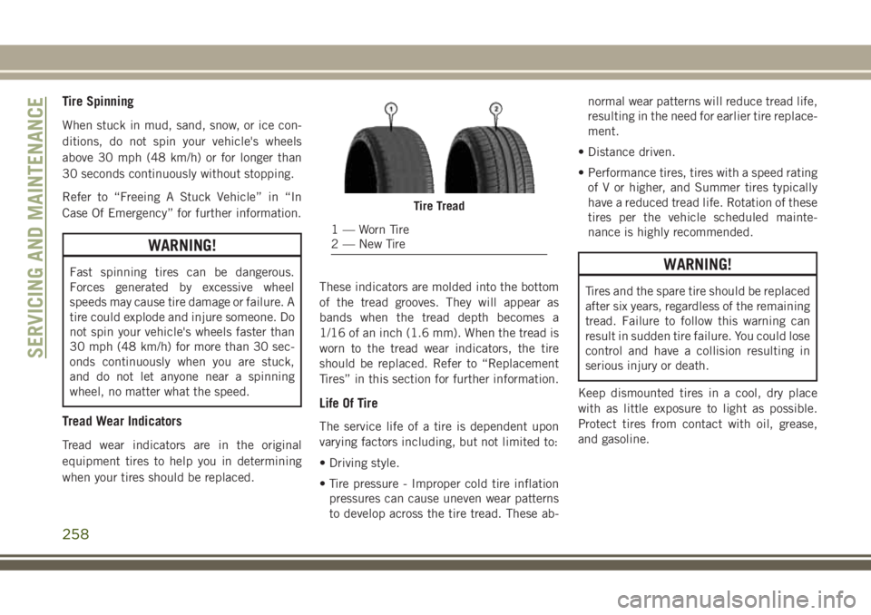
Tread Wear Indicators
Tread wear indicators are in the original
equipment tires to help you in determining
when your tires should be replaced.These indicators are molded into the bottom
of the tread grooves. They will appear as
bands when the tread depth becomes a
1/16 of an inch (1.6 mm). When the tread is
worn to the tread wear indicators, the tire
should be replaced. Refer to “Replacement
Tires” in this section for further information.
Life Of Tire
The service life of a tire is dependent upon
varying factors including, but not limited to:
• Driving style.
• Tire pressure - Improper cold tire inflation
pressures can cause uneven wear patterns
to develop across the tire tread. These ab-normal wear patterns will reduce tread life,
resulting in the need for earlier tire replace-
ment.
• Distance driven.
• Performance tires, tires with a speed rating
of V or higher, and Summer tires typically
have a reduced tread life. Rotation of these
tires per the vehicle scheduled mainte-
nance is highly recommended.
WARNING!
Tires and the spare tire should be replaced
after six years, regardless of the remaining
tread. Failure to follow this warning can
result in sudden tire failure. You could lose
control and have a collision resulting in
serious injury or death.
Keep dismounted tires in a cool, dry place
with as little exposure to light as possible.
Protect tires from contact with oil, grease,
and gasoline.
Tire Tread
1 — Worn Tire
2 — New Tire
SERVICING AND MAINTENANCE
258