ESP JEEP GRAND CHEROKEE 2018 Owner handbook (in English)
[x] Cancel search | Manufacturer: JEEP, Model Year: 2018, Model line: GRAND CHEROKEE, Model: JEEP GRAND CHEROKEE 2018Pages: 368, PDF Size: 5.72 MB
Page 146 of 368
The engine oil installed in the engine at the
factory is a high-quality energy conserving
type lubricant. Oil changes should be consis-
tent with anticipated climate conditions un-
der which vehicle operations will occur. The
recommended viscosity and quality grades
are shown under “Fluids And Lubricants” in
"Technical Specifications” in this manual.
NON-DETERGENT OR STRAIGHT MINERAL
OILS MUST NEVER BE USED.
SRT Engines
The following tips will be helpful in obtaining
optimum performance and maximum dura-
bility for your new SRT Vehicle.
Despite modern technology and World Class
manufacturing methods, the moving parts of
the vehicle must still wear in with each other.
This wearing in occurs mainly during the first
500 miles (805 km) and continues through
the first oil change interval.It is recommended for the operator to observe
the following driving behaviors during the
new vehicle break-in period:
0 to 100 miles (0 to 161 km):
• Do not allow the engine to operate at idle
for an extended period of time.
• Depress the accelerator pedal slowly and
not more than halfway to avoid rapid accel-
eration.
• Avoid aggressive braking.
• Drive with the engine speed less than
3,500 RPM.
• Maintain vehicle speed below 55 mph
(88 km/h) and observe local speed limits.
100 to 300 miles (161 to 483 km):
• Depress the accelerator pedal slowly and
not more than halfway to avoid rapid accel-
eration in lower gears (1st to 3rd gears).
• Avoid aggressive braking.
• Drive with the engine speed less than
5,000 RPM.• Maintain vehicle speed below 70 mph
(112 km/h) and observe local speed limits.
300 to 500 miles (483 to 805 km):
• Exercise the full engine rpm range, shifting
manually (paddles or gear shift) at higher
rpms when possible.
• Do not perform sustained operation with
the accelerator pedal at wide open throttle.
• Maintain vehicle speed below 85 mph
(136 km/h) and observe local speed limits.
For the first 1500 miles (2414 km):
• Do not participate in track events, sport
driving schools, or similar activities during
the first 1500 mi (2414 km).
NOTE:
Check engine oil with every refueling and add
if necessary. Oil and fuel consumption may
be higher through the first oil change inter-
val. Running the engine with an oil level
below the add mark can cause severe engine
damage.
STARTING AND OPERATING
144
Page 151 of 368
NOTE:
When Selec-Speed or Hill Descent Control is
enabled, AutoStick is not active.
To disengage AutoStick, return the gear se-
lector to the DRIVE position, or press and
hold the (+) shift paddle (if the gear selector
is already in DRIVE) until "D" is once again
indicated in the instrument cluster. You can
shift in or out of AutoStick at any time with-
out taking your foot off the accelerator pedal.
WARNING!
Do not downshift for additional engine
braking on a slippery surface. The drive
wheels could lose their grip and the ve-
hicle could skid, causing a collision or
personal injury.
SPORT MODE — IF
EQUIPPED
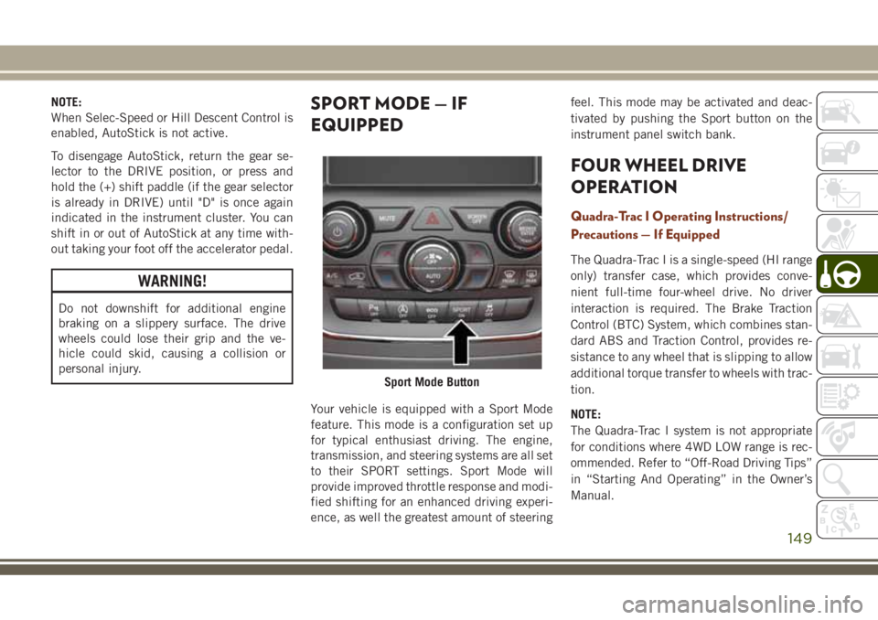
Your vehicle is equipped with a Sport Mode
feature. This mode is a configuration set up
for typical enthusiast driving. The engine,
transmission, and steering systems are all set
to their SPORT settings. Sport Mode will
provide improved throttle response and modi-
fied shifting for an enhanced driving experi-
ence, as well the greatest amount of steeringfeel. This mode may be activated and deac-
tivated by pushing the Sport button on the
instrument panel switch bank.
FOUR WHEEL DRIVE
OPERATION
Quadra-Trac I Operating Instructions/
Precautions — If Equipped
The Quadra-Trac I is a single-speed (HI range
only) transfer case, which provides conve-
nient full-time four-wheel drive. No driver
interaction is required. The Brake Traction
Control (BTC) System, which combines stan-
dard ABS and Traction Control, provides re-
sistance to any wheel that is slipping to allow
additional torque transfer to wheels with trac-
tion.
NOTE:
The Quadra-Trac I system is not appropriate
for conditions where 4WD LOW range is rec-
ommended. Refer to “Off-Road Driving Tips”
in “Starting And Operating” in the Owner’s
Manual.
Sport Mode Button
149
Page 171 of 368
ACC Operation At Stop
If the ACC system brings your vehicle to a
standstill while following a target vehicle, if
the target vehicle starts moving within two
seconds of your vehicle coming to a stand-
still, your vehicle will resume motion without
the need for any driver action.
If the target vehicle does not start moving
within two seconds of your vehicle coming to
a standstill, the ACC with Stop system will
cancel and the brakes will release. A cancel
message will display on the instrument clus-
ter display and produce a warning chime.
Driver intervention will be required at this
moment.
While ACC with Stop is holding your vehicle
at a standstill, if the driver seatbelt is un-
buckled or the driver door is opened, the ACC
with Stop system will cancel and the brakes
will release. A cancel message will display on
the instrument cluster display and produce a
warning chime. Driver intervention will be
required at this moment.
WARNING!
When the ACC system is resumed, the
driver must ensure that there are no pedes-
trians, vehicles or objects in the path of
the vehicle. Failure to follow these warn-
ings can result in a collision and death or
serious personal injury.
Changing Modes
If desired, the Adaptive Cruise Control mode
can be turned off and the system can be
operated as a Normal (Fixed Speed) Cruise
Control mode. When in the Normal (Fixed
Speed) Cruise Control mode the distance
setting feature will be disabled and the sys-
tem will maintain the speed you set.
• To change between the different cruise con-
trol modes, push the Adaptive Cruise Con-
trol (ACC) on/off button which turns the
ACC and the Normal (Fixed Speed) Cruise
Control off.
• Pushing the Normal (Fixed Speed) Cruise
Control on/off button will result in turning
on (changing to) the Normal (Fixed Speed)
Cruise Control mode.Refer to your Owner's Manual for further
information.
WARNING!
Adaptive Cruise Control (ACC) is a conve-
nience system. It is not a substitute for
active driving involvement. It is always the
driver’s responsibility to be attentive of
road, traffic, and weather conditions, ve-
hicle speed, distance to the vehicle ahead;
and, most importantly, brake operation to
ensure safe operation of the vehicle under
all road conditions. Your complete atten-
tion is always required while driving to
maintain safe control of your vehicle. Fail-
ure to follow these warnings can result in a
collision and death or serious personal
injury.
The ACC system:
• Does not react to pedestrians, oncoming
vehicles, and stationary objects (e.g., a
stopped vehicle in a traffic jam or a
disabled vehicle).
• Cannot take street, traffic, and weather
conditions into account, and may be
169
Page 174 of 368
WARNING!
• Drivers must be careful when backing up
even when using ParkSense. Always
check carefully behind your vehicle,
look behind you, and be sure to check
for pedestrians, animals, other vehicles,
obstructions, and blind spots before
backing up. You are responsible for
safety and must continue to pay atten-
tion to your surroundings. Failure to do
so can result in serious injury or death.
• Before using ParkSense, it is strongly
recommended that the ball mount and
hitch ball assembly is disconnected
from the vehicle when the vehicle is not
used for towing. Failure to do so can
result in injury or damage to vehicles or
obstacles because the hitch ball will be
much closer to the obstacle than the
rear fascia when the loudspeaker sounds
the continuous tone. Also, the sensors
could detect the ball mount and hitch
ball assembly, depending on its size and
shape, giving a false indication that an
obstacle is behind the vehicle.
CAUTION!
• ParkSense is only a parking aid and it is
unable to recognize every obstacle, in-
cluding small obstacles. Parking curbs
might be temporarily detected or not
detected at all. Obstacles located above
or below the sensors will not be detected
when they are in close proximity.
• The vehicle must be driven slowly when
using ParkSense in order to be able to
stop in time when an obstacle is de-
tected. It is recommended that the
driver looks over his/her shoulder when
using ParkSense.
PARKSENSE FRONT AND
REAR PARK ASSIST
ParkSense Sensors
The four ParkSense sensors, located in the
rear fascia/bumper, monitor the area behind
the vehicle that is within the sensors field of
view. The sensors can detect obstacles from
approximately 12 inches (30 cm) up to79 inches (200 cm) from the rear fascia/
bumper in the horizontal direction, depend-
ing on the location, type and orientation of
the obstacle.
The six ParkSense sensors, located in the
front fascia/bumper, monitor the area in front
of the vehicle that is within the sensors’ field
of view. The sensors can detect obstacles
from approximately 12 inches (30 cm) up to
47 inches (120 cm) from the front fascia/
bumper in the horizontal direction, depend-
ing on the location, type and orientation of
the obstacle.
When an object is detected within 79 inches
(200 cm) behind the rear bumper while the
vehicle is in REVERSE, a warning will appear
in the instrument cluster display. In addition
a chime will sound (when Sound and Display
is selected from the Customer Programmable
Features section of the Uconnect System
screen). As the vehicle moves closer to the
object, the chime rate will change from single
1/2 second tone (for rear only), to slow (for
rear only), to fast, to continuous.
STARTING AND OPERATING
172
Page 176 of 368
PARKSENSE ACTIVE PARK
ASSIST SYSTEM — IF
EQUIPPED
The ParkSense Active Park Assist system is
intended to assist the driver during parallel
and perpendicular parking maneuvers by
identifying a proper parking space, providing
audible/visual instructions, and controlling
the steering wheel. The ParkSense Active
Park Assist system is defined as “semi-
automatic” since the driver maintains control
of the accelerator, gear selector and brakes.
Depending on the driver's parking maneuver
selection, the ParkSense Active Park Assist
system is capable of maneuvering a vehicle
into a parallel or a perpendicular parking
space on either side (i.e., driver side or pas-
senger side).
NOTE:
• The driver is always responsible for control-
ling the vehicle, responsible for any sur-
rounding objects, and must intervene as
required.• The system is provided to assist the driver
and not to substitute the driver.
• During a semi-automatic maneuver, if the
driver touches the steering wheel after be-
ing instructed to remove their hands from
the steering wheel, the system will cancel,
and the driver will be required to manually
complete the parking maneuver.
• The system may not work in all conditions
(e.g. environmental conditions such as
heavy rain, snow, etc., or if searching for a
parking space that has surfaces that will
absorb the ultrasonic sensor waves).
• New vehicles from the dealership must
have at least 30 miles (48 km) accumu-
lated before the ParkSense Active Park
Assist system is fully calibrated and per-
forms accurately. This is due to the sys-
tem’s dynamic vehicle calibration to im-
prove the performance of the feature. The
system will also continuously perform the
dynamic vehicle calibration to account for
differences such as over or under inflated
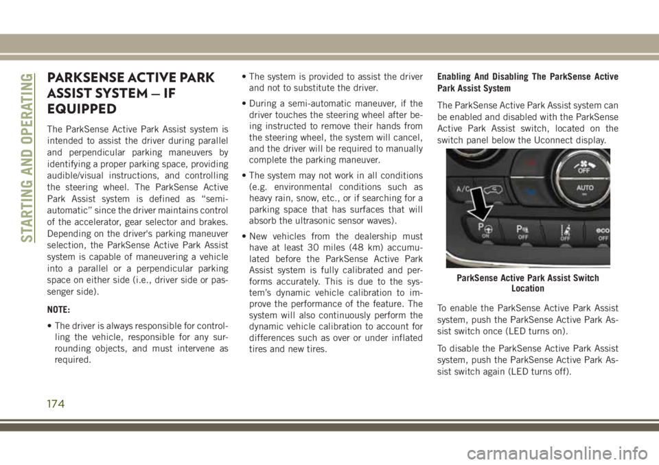
tires and new tires.Enabling And Disabling The ParkSense Active
Park Assist System
The ParkSense Active Park Assist system can
be enabled and disabled with the ParkSense
Active Park Assist switch, located on the
switch panel below the Uconnect display.
To enable the ParkSense Active Park Assist
system, push the ParkSense Active Park As-
sist switch once (LED turns on).
To disable the ParkSense Active Park Assist
system, push the ParkSense Active Park As-
sist switch again (LED turns off).
ParkSense Active Park Assist Switch
Location
STARTING AND OPERATING
174
Page 186 of 368
CAUTION!
•To avoid DEF spillage, and possible dam-
age to the DEF tank from overfilling, do
not “top off” the DEF tank after filling.
• DO NOT OVERFILL. DEF will freeze be-
low 12ºF (-11ºC). The DEF system is
designed to work in temperatures below
the DEF freezing point, however, if the
tank is overfilled and freezes, the system
could be damaged.
• When DEF is spilled, clean the area
immediately with water and use an ab-
sorbent material to soak up the spills on
the ground.
• Do not attempt to start your engine if
DEF is accidentally added to the diesel
fuel tank as it can result in severe dam-
age to your engine, including but not
limited to failure of the fuel pump and
injectors.
CAUTION!
• Never add anything other than DEF to
the tank – especially any form of hydro-
carbon such as diesel fuel, fuel system
additives, gasoline, or any other
petroleum-based product. Even a very
small amount of these, less than
100 parts per million or less than 1 oz.
(30 ml) per 78 gallons (295 liters) will
contaminate the entire DEF system and
will require replacement. If owners use a
container, funnel or nozzle when refilling
the tank, it should either be new or one
that is has only been used for adding
DEF. Mopar provides an attachable
nozzle with its DEF for this purpose.3. Stop filling the DEF tank immediately
when any of the following happen: DEF
stops flowing from the fill bottle into the
DEF fill inlet, DEF splashes out the fill
inlet, or a DEF pump nozzle automatically
shuts off.
4. Reinstall cap onto DEF fill inlet.
STARTING AND OPERATING
184
Page 199 of 368
IN CASE OF EMERGENCY
HAZARD WARNING FLASHERS .198
Control....................198
BULB REPLACEMENT........198
Replacement Bulbs.............198
Bulb Replacement.............200
FUSES...................204
General Information.............204
Underhood Fuses..............204
JACKING AND TIRE CHANGING. .209
Run Flat Tires — SRT Models.......209
Jack Location................209Preparations For Jacking.........210
Jacking Instructions............210
Road Tire Installation............214
Declaration Of Conformance.......214
Jack Usage Precautions..........217
JUMP STARTING............217
Preparations For Jump Start........218
Jump Starting Procedure..........219
REFUELING IN EMERGENCY . . .220
IF YOUR ENGINE OVERHEATS .220
MANUAL PARK RELEASE......221FREEING A STUCK VEHICLE . . .222
TOWING A DISABLED VEHICLE .223
Without The Key Fob............225
Two-Wheel Drive Models..........225
Four-Wheel Drive Models.........225
Tow Eye Usage — If Equipped......226
Emergency Tow Hooks — If Equipped .227
ENHANCED ACCIDENT RESPONSE
SYSTEM (EARS)............228
EVENT DATA RECORDER (EDR) .228
IN CASE OF EMERGENCY
197
Page 206 of 368
FUSES
WARNING!
• When replacing a blown fuse, always use
an appropriate replacement fuse with
the same amp rating as the original fuse.
Never replace a fuse with another fuse of
higher amp rating. Never replace a
blown fuse with metal wires or any other
material. Do not place a fuse inside a
circuit breaker cavity or vice versa. Fail-
ure to use proper fuses may result in
serious personal injury, fire and/or prop-
erty damage.
• Before replacing a fuse, make sure that
the ignition is off and that all the other
services are switched off and/or disen-
gaged.
• If the replaced fuse blows again, contact
an authorized dealer.
• If a general protection fuse for safety
systems (air bag system, braking sys-
WARNING!
tem), power unit systems (engine sys-
tem, transmission system) or steering
system blows, contact an authorized
dealer.
General Information
The fuses protect electrical systems against
excessive current.
When a device does not work, you must check
the fuse element inside the blade fuse for a
break/melt.
Also, please be aware that when using power
outlets for extended periods of time with the
engine off may result in vehicle battery dis-
charge.
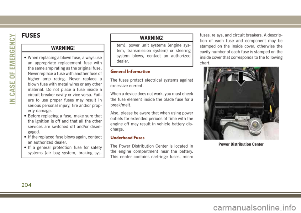
Underhood Fuses
The Power Distribution Center is located in
the engine compartment near the battery.
This center contains cartridge fuses, microfuses, relays, and circuit breakers. A descrip-
tion of each fuse and component may be
stamped on the inside cover, otherwise the
cavity number of each fuse is stamped on the
inside cover that corresponds to the following
chart.Power Distribution Center
IN CASE OF EMERGENCY
204
Page 230 of 368
ENHANCED ACCIDENT
RESPONSE SYSTEM (EARS)
This vehicle is equipped with an Enhanced
Accident Response System.
Please refer to “Occupant Restraint Sys-
tems” in “Safety” for further information on
the Enhanced Accident Response System
(EARS) function.
EVENT DATA RECORDER
(EDR)
This vehicle is equipped with an Event Data
Recorder (EDR). The main purpose of an EDR
is to record data that will assist in under-
standing how a vehicle’s systems performed
under certain crash or near crash-like situa-
tions, such as an air bag deployment or hit-
ting a road obstacle.Please refer to “Occupant Restraint Sys-
tems” in “Safety” for further information on
the Event Data Recorder (EDR).
IN CASE OF EMERGENCY
228
Page 258 of 368
WARNING!
• Always drive with each tire inflated to
the recommended cold tire inflation
pressure.
Both under-inflation and over-inflation affect
the stability of the vehicle and can produce a
feeling of sluggish response or over respon-
siveness in the steering.
NOTE:
• Unequal tire pressures from side to side
may cause erratic and unpredictable steer-
ing response.
• Unequal tire pressure from side to side may
cause the vehicle to drift left or right.
Fuel Economy
Underinflated tires will increase tire rolling
resistance resulting in higher fuel consump-
tion.
Tread Wear
Improper cold tire inflation pressures can
cause abnormal wear patterns and reduced
tread life, resulting in the need for earlier tire
replacement.Ride Comfort And Vehicle Stability
Proper tire inflation contributes to a comfort-
able ride. Over-inflation produces a jarring
and uncomfortable ride.
Tire Inflation Pressures
The proper cold tire inflation pressure is
listed on the left side B-Pillar or rear edge of
the passenger door.
At least once a month:
• Check and adjust tire pressure with a good
quality pocket-type pressure gauge. Do not
make a visual judgement when determining
proper inflation. Tires may look properly
inflated even when they are under-inflated.
• Inspect tires for signs of tire wear or visible
damage.
CAUTION!
After inspecting or adjusting the tire pres-
sure, always reinstall the valve stem cap.
This will prevent moisture and dirt from
entering the valve stem, which could dam-
age the valve stem.Inflation pressures specified on the placard
are always “cold tire inflation pressure”. Cold
tire inflation pressure is defined as the tire
pressure after the vehicle has not been driven
for at least three hours, or driven less than
1 mile (1.6 km) after sitting for a minimum of
three hours. The cold tire inflation pressure
must not exceed the maximum inflation pres-
sure molded into the tire sidewall.
Check tire pressures more often if subject to
a wide range of outdoor temperatures, as tire
pressures vary with temperature changes.
Tire pressures change by approximately 1 psi
(7 kPa) per 12°F (7°C) of air temperature
change. Keep this in mind when checking
tire pressure inside a garage, especially in the
Winter.
Example: If garage temperature = 68°F
(20°C) and the outside temperature = 32°F
(0°C) then the cold tire inflation pressure
should be increased by 3 psi (21 kPa), which
equals 1 psi (7 kPa) for every 12°F (7°C) for
this outside temperature condition.
SERVICING AND MAINTENANCE
256