display JEEP GRAND CHEROKEE 2018 Owner handbook (in English)
[x] Cancel search | Manufacturer: JEEP, Model Year: 2018, Model line: GRAND CHEROKEE, Model: JEEP GRAND CHEROKEE 2018Pages: 368, PDF Size: 5.72 MB
Page 87 of 368

should be used for most driving conditions.
Alternate ESC modes should only be used for
specific reasons as noted in the following
paragraphs.
Partial Off
The “Partial Off” mode is intended for times
when a more spirited driving experience is
desired. This mode may modify TCS and ESC
thresholds for activation, which allows for
more wheel spin than normally allowed. This
mode may be useful if the vehicle becomes
stuck.
To enter the “Partial Off” mode, momentarily
push the “ESC Off” switch and the “ESC Off
Indicator Light” will illuminate. To turn the
ESC on again, momentarily push the “ESC
Off” switch and the “ESC Off Indicator Light”
will turn off.
NOTE:
For vehicles with multiple partial ESC modes
a momentary button push will toggle the ESC
mode. Multiple momentary button pushed
may be required to return to ESC On.WARNING!
• When in “Partial Off” mode, the TCS
functionality of ESC, (except for the lim-
ited slip feature described in the TCS
section), has been disabled and the
“ESC Off Indicator Light” will be illumi-
nated. When in “Partial Off” mode, the
engine power reduction feature of TCS is
disabled, and the enhanced vehicle sta-
bility offered by the ESC system is re-
duced.
• Trailer Sway control (TSC) is disabled
when the ESC system is in the “Partial
Off” mode.
Full Off — If Equipped
This mode is intended for off-highway or
off-road use only and should not be used on
any public roadways. In this mode, TCS and
ESC features are turned OFF. To enter the
“Full Off” mode, push and hold the “ESC
Off” switch for five seconds while the vehicle
is stopped with the engine running. After five
seconds, a chime will sound, the “ESC Off
Indicator Light” will illuminate, and the“ESC OFF” message will display in the in-
strument cluster. To turn ESC ON again,
momentarily push the “ESC Off” switch.
NOTE:
System may switch from ESC “Full Off” to
“Partial Off” mode when vehicle exceeds a
predetermined speed. When the vehicle
speed slows below the predetermined speed
the system will return to ESC “Full Off”.
“Full Off” can only be achieved in Track
Mode if so equipped.
ESC modes may also be affected by drive
modes if so equipped.
WARNING!
• In the ESC “Full Off” mode, the engine
torque reduction and stability features
are disabled. Therefore, enhanced ve-
hicle stability offered by the ESC system
is unavailable. In an emergency evasive
maneuver, the ESC system will not en-
gage to assist in maintaining stability.
ESC “Full Off” mode is intended for
off-highway or off-road use only.
85
Page 95 of 368
rear end of the vehicle is exposed. The RCP
system will then have a clear view of the cross
traffic and if an oncoming vehicle is de-
tected, will alert the driver. When RCP is on
and the vehicle is in REVERSE, the driver is
alerted using both the visual and audible
alarms, including reducing the radio volume.
Refer to “Blind Spot Monitoring” in “Safety”
in the Owner's Manual for more information.
Modes Of Operation
Three selectable modes of operation are
available in the Uconnect System. Refer to
“Uconnect Settings” in “Multimedia” in the
Owner’s Manual for further information.
Blind Spot Alert Lights Only
When operating in Blind Spot Alert mode, the
BSM system will provide a visual alert in the
appropriate side view mirror based on a de-
tected object. However, when the system is
operating in Rear Cross Path (RCP) mode, the
system will respond with both visual and
audible alerts when a detected object is pres-
ent. Whenever an audible alert is requested,
the radio is muted.Blind Spot Alert Lights/Chime
When operating in Blind Spot Alert Lights/
Chime mode, the BSM system will provide a
visual alert in the appropriate side view mirror
based on a detected object. If the turn signal
is then activated, and it corresponds to an
alert present on that side of the vehicle, an
audible chime will also be sounded. When-
ever a turn signal and detected object are
present on the same side at the same time,
both the visual and audible alerts will be
issued. In addition to the audible alert the
radio (if on) will also be muted.
NOTE:
Whenever an audible alert is requested by the
BSM system, the radio is also muted.
When the system is in RCP, the system shall
respond with both visual and audible alerts
when a detected object is present. Whenever
an audible alert is requested, the radio is also
muted. Turn/hazard signal status is ignored;
the RCP state always requests the chime.Blind Spot Alert Off
When the BSM system is turned off there will
be no visual or audible alerts from either the
BSM or RCP systems.
NOTE:
The BSM system will store the current oper-
ating mode when the vehicle is shut off. Each
time the vehicle is started the previously
stored mode will be recalled and used.
Forward Collision Warning (FCW)
The Forward Collision Warning (FCW) system pro-
vides the driver with audible and visual warnings
within the instrument cluster display to warn the
driver when it detects a potential frontal collision.
The warnings are intended to provide the driver
with enough time to react, avoid or mitigate the
potential collision.
NOTE:
FCW monitors the information from the for-
ward looking sensors as well as the Electronic
Brake Controller (EBC), to calculate the prob-
ability of a forward collision. When the sys-
tem determines that a forward collision is
probable, the driver will be provided with
audible and visual warnings.
93
Page 96 of 368
Changing FCW System Status
The Forward Collision Warning settings are
located in the Uconnect display in the con-
trols settings.
NOTE:
• The default sensitivity of FCW is the “Me-
dium” setting and the system status is
“Warning & Braking”. This allows the sys-
tem to warn the driver of a possible colli-
sion with the vehicle in front using audible/
visual warnings and it applies autonomous
braking.
• Changing the FCW status to “Only Warn-
ing” prevents the system from providing
limited active braking, or additional brake
support if the driver is not braking ad-
equately in the event of a potential frontal
collision, but maintains the audible and
visual warnings.
• Changing the FCW status to “Off” prevents
the system from providing autonomous
braking, or additional brake support if the
driver is not braking adequately in the event
of a potential frontal collision. If FCW is set
to “Off”, “FCW OFF” will appear in the
instrument cluster display.Changing FCW Sensitivity
The FCW feature has three settings and can
be changed within the Uconnect System
Screen:
• Far
• Medium
• Near
Far
The far setting provides warnings for poten-
tial collisions more distant in front of the
vehicle, allowing the driver to have the most
reaction time to avoid a collision.
More cautious drivers that do not mind fre-
quent warnings may prefer this setting.
NOTE:
This setting gives you the most reaction time.
Medium
The default sensitivity of FCW is the “Me-
dium” setting and the system status is
“Warning & Braking”. This allows the system
to warn the driver of a possible collision with
the vehicle in front using audible/visual warn-
ings and it applies autonomous braking.Near
Changing the FCW sensitivity to the “Near”
setting, allows the system to warn you of a
potential frontal collision when you are much
closer.
This setting provides less reaction time than
the “Far” setting, which allows for a more
dynamic driving experience.
More dynamic or aggressive drivers that want
to avoid frequent warnings may prefer this
setting.
Refer to your Owner's Manual for further
details.
WARNING!
Forward Collision Warning (FCW) is not
intended to avoid a collision on its own,
nor can FCW detect every type of potential
collision. The driver has the responsibility
to avoid a collision by controlling the ve-
hicle via braking and steering. Failure to
follow this warning could lead to serious
injury or death.
SAFETY
94
Page 99 of 368
NOTE:
It is particularly important, for you to regu-
larly check the tire pressure in all of your tires
and to maintain the proper pressure.
The Tire Pressure Monitor System (TPMS)
consists of the following components:
• Receiver Module
• Four Tire Pressure Monitoring Sensors• Various Tire Pressure Monitoring System
Messages, which display in the instrument
cluster, and a graphic displaying tire pres-
sures
• Tire Pressure Monitoring Telltale Light
Tire Pressure Monitoring Low Pressure
Warnings
The Tire Pressure Monitoring
Telltale Light will illuminate in
the instrument cluster, and an
audible chime will be activated,
when one or more of the four
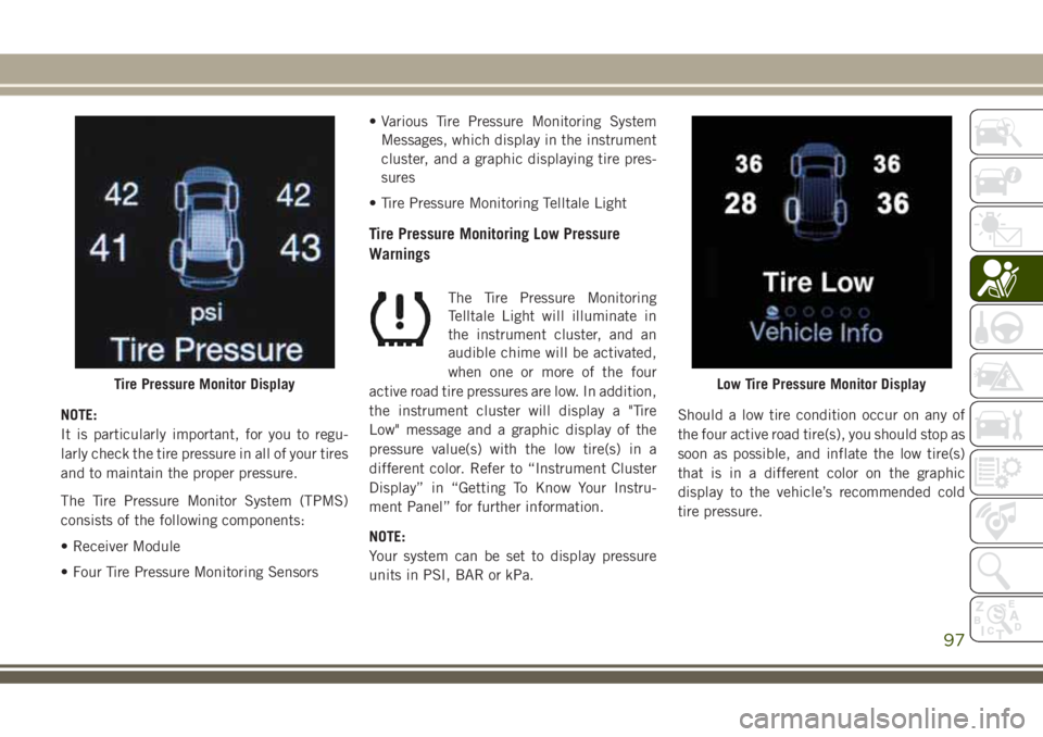
active road tire pressures are low. In addition,
the instrument cluster will display a "Tire
Low" message and a graphic display of the
pressure value(s) with the low tire(s) in a
different color. Refer to “Instrument Cluster
Display” in “Getting To Know Your Instru-
ment Panel” for further information.
NOTE:
Your system can be set to display pressure
units in PSI, BAR or kPa.Should a low tire condition occur on any of
the four active road tire(s), you should stop as
soon as possible, and inflate the low tire(s)
that is in a different color on the graphic
display to the vehicle’s recommended cold
tire pressure.
Tire Pressure Monitor DisplayLow Tire Pressure Monitor Display
97
Page 100 of 368
NOTE:
When filling warm tires, the tire pressure may
need to be increased up to an additional 4 psi
(28 kPa) above the recommended cold plac-
ard pressure in order to turn the Tire Pressure
Monitoring Telltale Light off.
The system will automatically update, the
graphic display of the pressure value(s) will
return to its original color and the Tire Pres-
sure Monitoring Telltale Light will extinguish
once the updated tire pressure(s) have been
received. The vehicle may need to be driven
for up to 10 minutes above 15 mph
(24 km/h) to receive this information.
Service TPM System Warning
The Tire Pressure Monitoring Telltale Light
will flash on and off for 75 seconds, and
remain on solid when a system fault is de-
tected. The system fault will also sound a
chime. The instrument cluster display will
display a “SERVICE TPM SYSTEM” message
for a minimum of five seconds. This message
is then followed by a graphic display, with “-
-“ in place of the pressure value(s), indicat-
ing which Tire Pressure Monitoring Sensor(s)
is not being received.If the ignition switch is cycled, this sequence
will repeat, providing the system fault still
exists. If the system fault no longer exists, the
Tire Pressure Monitoring Telltale Light will no
longer flash, the "SERVICE TPM SYSTEM"
message will not be present, and a pressure
value will be displayed instead of dashes. A
system fault can occur by any of the follow-
ing:
• Jamming due to electronic devices or driv-
ing next to facilities emitting the same
Radio Frequencies as the TPM sensors.
• Installing some form of aftermarket window
tinting that affects radio wave signals.
• Lots of snow or ice around the wheels or
wheel housings.
• Using tire chains on the vehicle.
• Using wheels/tires not equipped with TPM
sensors.
NOTE:
There is no tire pressure monitoring sensor in
the spare tire. The TPMS will not be able to
monitor the tire pressure. If you install the
spare tire in place of a road tire that has a
pressure below the low-pressure warninglimit, upon the next ignition switch cycle, the
Tire Pressure Monitoring Telltale Light will
remain on, a chime will sound, and the in-
strument cluster display will still display a
pressure value in the different color graphic
display. After driving the vehicle for up to
10 minutes above 15 mph (24 km/h), the
Tire Pressure Monitoring Telltale Light will
flash on and off for 75 seconds and then
remain on solid. In addition, the instrument
cluster display will display a “SERVICE TPM
SYSTEM" message for five seconds and then
display dashes (- -) in place of the pressure
value. For each subsequent ignition switch
cycle, a chime will sound, the Tire Pressure
Monitoring Telltale Light will flash on and off
for 75 seconds and then remain on solid, and
the instrument cluster display will display a
"SERVICE TPM SYSTEM" message for five
seconds and then display dashes (- -) in place
of the pressure value. Once you repair or
replace the original road tire, and reinstall it
on the vehicle in place of the spare tire, the
TPMS will update automatically.
In addition, the Tire Pressure Monitoring Tell-
tale Light will turn off and the graphic in the
instrument cluster display will display a new
SAFETY
98
Page 101 of 368
pressure value instead of dashes (- -), as long
as no tire pressure is below the low-pressure
warning limit in any of the four active road
tires. The vehicle may need to be driven for
up to 10 minutes above 15 mph (24 km/h) in
order for the TPMS to receive this informa-
tion.
TPMS Deactivation — If Equipped
The TPMS can be deactivated if replacing all
four wheel and tire assemblies (road tires)
with wheel and tire assemblies that do not
have TPMS Sensors, such as when installing
winter wheel and tire assemblies on your
vehicle.
To deactivate the TPMS, first, replace all four
wheel and tire assemblies (road tires) with
tires not equipped with Tire Pressure Moni-
toring (TPM) Sensors. Then, drive the vehicle
for 10 minutes above 15 mph (24 km/h). The
TPMS will chime, the "TPM Telltale Light"
will flash on and off for 75 seconds and then
remain on. The instrument cluster will dis-
play the “SERVICE TPM SYSTEM” message
and then display dashes (--) in place of the
pressure values.Beginning with the next ignition cycle, the
TPMS will no longer chime or display the
“SERVICE TPM SYSTEM” message in the
instrument cluster but dashes (--) will remain
in place of the pressure values.
To reactivate the TPMS, replace all four
wheel and tire assemblies (road tires) with
tires equipped with TPM sensors. Then, drive
the vehicle for up to 10 minutes above
15 mph (24 km/h). The TPMS will chime, the
"TPM Telltale Light" will flash on and off for
75 seconds and then turn off. The instrument
cluster will display the “SERVICE TPM SYS-
TEM” message and then display pressure
values in place of the dashes. On the next
ignition cycle the "SERVICE TPM SYSTEM"
message will no longer be displayed as long
as no system fault exists.
OCCUPANT RESTRAINT
SYSTEMS
Some of the most important safety features in
your vehicle are the restraint systems:
Occupant Restraint Systems Features
• Seat Belt Systems
• Supplemental Restraint Systems (SRS) Air
Bags
• Supplemental Active Head Restraints
• Child Restraints
Some of the safety features described in this
section may be standard equipment on some
models, or may be optional equipment on
others. If you are not sure, ask your autho-
rized dealer.
Important Safety Precautions
Please pay close attention to the information
in this section. It tells you how to use your
restraint system properly, to keep you and
your passengers as safe as possible.
Here are some simple steps you can take to
minimize the risk of harm from a deploying
air bag:
1. Children 12 years old and under should
always ride buckled up in the rear seat of
a vehicle with a rear seat.
99
Page 137 of 368
STARTING AND OPERATING
STARTING THE ENGINE — GAS . .137
Automatic Transmission..........137
Normal Starting...............137
STARTING THE ENGINE — 3.0L DIE-
SEL ENGINE................139
Automatic Transmission..........140
Normal Starting...............140
STOP/START SYSTEM — IF
EQUIPPED.................140
Automatic Mode...............140
Possible Reasons The Engine Does Not
Autostop...................141
To Start The Engine While In Autostop
Mode.....................142
To Manually Turn Off The Stop/Start
System....................142
To Manually Turn On The Stop/Start
System....................142
System Malfunction............142
ENGINE BREAK-IN RECOMMENDA-
TIONS....................143
3.6L & 5.7L Engines............143Diesel Engine................143
SRT Engines.................144
AUTOMATIC TRANSMISSION . . .145
Ignition Park Interlock...........146
Brake/Transmission Shift Interlock
System....................146
Fuel Economy (ECO) Mode........146
Eight–Speed Automatic Transmission . .147
SPORT MODE — IF EQUIPPED . .149
FOUR WHEEL DRIVE OPERATION.149
Quadra-Trac I Operating Instructions/
Precautions — If Equipped........149
Quadra-Trac II Operating Instructions/
Precautions — If Equipped........150
Shift Positions................150
Shifting Procedures.............151
Quadra-Drive II System — If Equipped .153
QUADRA-LIFT — IF EQUIPPED . .154
Description.................154
Air Suspension Modes...........156
Instrument Cluster Display Messages . .157Operation..................157
SELEC-TERRAIN — IF
EQUIPPED.................158
Selec-Terrain Mode Selection.......158
Instrument Cluster Display Messages . .159
SELEC-TRACK — IF EQUIPPED
(SRT).....................159
Custom....................160
Active Damping System..........160
Launch Control— If Equipped......160
Guidelines For Track Use.........162
SPEED CONTROL............163
Activation...................164
Setting A Desired Speed.........164
Varying The Speed.............164
Resume Speed...............165
Accelerating For Passing.........165
Deactivation.................165
ADAPTIVE CRUISE CONTROL
(ACC) ....................165
Activation..................166
STARTING AND OPERATING
135
Page 138 of 368

Setting A Desired Speed..........166
Varying The Speed.............166
To Resume..................168
Deactivation.................168
Setting The Following Distance......168
ACC Operation At Stop...........169
Changing Modes..............169
PARKSENSE REAR PARK ASSIST. .170
ParkSense Sensors.............170
Activation/Deactivation ParkSense. . . .170
Instrument Cluster Display........171
ParkSense System Usage Precautions . .171
PARKSENSE FRONT AND REAR
PARKASSIST...............172
ParkSense Sensors.............172
Activation/Deactivation...........173
Engagement/Disengagement.......173
Operation With A Trailer..........173
General Warnings..............173
PARKSENSE ACTIVE PARK ASSIST
SYSTEM — IF EQUIPPED......174
LANESENSE................175
LaneSense Operation............175
Turning LaneSense On Or Off.......176
PARKVIEW REAR BACK-UP CAM-
ERA .....................176
Symbols And Messages On The Display .176
REFUELING THE VEHICLE — GASO-
LINE ENGINE...............177
Emergency Fuel Filler Door Release . . .178
REFUELING THE VEHICLE — DIE-
SEL ENGINE................179
Avoid Using Contaminated Fuel.....181
Bulk Fuel Storage — Diesel Fuel. . . .181
Diesel Exhaust Fluid............181
TRAILER TOWING...........185
Trailer Towing Weights (Maximum Trailer
Weight Ratings) — Non SRT.......185
Trailer Towing Weights (Maximum Trailer
Weight Ratings) — SRT..........187
Trailer Hitch Receiver Cover Removal
(Summit Models) — If Equipped.....188
Trailer Hitch Receiver Cover Removal (SRT
Models) — If Equipped..........189
RECREATIONAL TOWING (BEHIND
MOTORHOME, ETC.)..........191
Towing This Vehicle Behind Another
Vehicle....................191
Recreational Towing-Two Wheel Drive
Models....................192
Recreational Towing — Quadra-Trac I
(Single-Speed Transfer Case) Four-Wheel
Drive Models.................192
Recreational Towing — Quadra–Trac
II/Quadra–Drive II Four-Wheel Drive
Models....................193
STARTING AND OPERATING
136
Page 140 of 368
3. The system takes over and attempts to
start the vehicle. If the vehicle fails to
start, the starter will disengage automati-
cally after 10 seconds.
4. If you wish to stop the cranking of the
engine prior to the engine starting, push
the button again.
NOTE:
Normal starting of either a cold or a warm
engine is obtained without pumping or press-
ing the accelerator pedal.
To Turn Off The Engine Using ENGINE START/
STOP Button
1. Place the gear selector in PARK, then
push and release the ENGINE START/
STOP button.
2. The ignition will return to the OFF mode.
3. If the gear selector is not in PARK (with
vehicle stopped) and the ENGINE START/
STOP button is pushed once, the trans-
mission will automatically select PARK
and the engine will turn off, however theignition will remain in the ACC mode
(NOT the OFF mode). Never leave a ve-
hicle out of the PARK position, or it could
roll.
4. If the gear selector is in NEUTRAL, and
the vehicle speed is below 5 mph
(8 km/h), pushing the START/STOP but-
ton once will turn the engine off. The
ignition will remain in the ACC mode.
5. If the vehicle speed is above 5 mph
(8 km/h), the ENGINE START/STOP but-
ton must be held for two seconds (or three
short pushes in a row) to turn the engine
off. The ignition will remain in the ACC
mode (NOT the OFF mode) if the engine is
turned off when the transmission is not in
PARK.
NOTE:
The system will automatically time out and
the ignition will cycle to the OFF mode after
30 minutes of inactivity if the ignition is left
in the ACC or RUN (engine not running) mode
and the transmission is in PARK.ENGINE START/STOP Button Functions — With
Driver’s Foot OFF The Brake Pedal (In PARK Or
NEUTRAL Position)
The ENGINE START/STOP button operates
similar to an ignition switch. It has three
modes: OFF, ACC, and RUN. To change the
ignition modes without starting the vehicle
and use the accessories, follow these steps:
1. Starting with the ignition in the OFF
mode,
2. Push the ENGINE START/STOP button
once to place the ignition to the ACC
mode (instrument cluster will display
“ACC”),
3. Push the ENGINE START/STOP button a
second time to place the ignition to the
RUN mode (instrument cluster will dis-
play “ON/RUN”),
4. Push the ENGINE START/STOP button a
third time to return the ignition to the OFF
mode (instrument cluster will display
“OFF”).
STARTING AND OPERATING
138
Page 143 of 368
To Activate The Autostop Mode, The Following
Must Occur:
• The system must be in STOP/START
READY state. A STOP/START READY mes-
sage will be displayed in the instrument
cluster display within the Stop/Start sec-
tion. Refer to “Instrument Cluster” in “Get-
ting To Know Your Instrument Panel” in
your Owner’s Manual for further informa-
tion.
• The vehicle must be completely stopped.
• The shifter must be in a forward gear and
the brake pedal depressed.
The engine will shut down, the tachometer
will move to the zero position and the Stop/
Start telltale will illuminate indicating you
are in Autostop. Customer settings will be
maintained upon return to an engine running
condition.
Refer to the “Stop/Start System” in the
“Starting And Operating” section located in
your Owner’s Manual for further information.Possible Reasons The Engine Does Not
Autostop
Prior to engine shut down, the system will
check many safety and comfort conditions to
see if they are fulfilled. Detailed information
about the operation of the Stop/Start system
may be viewed in the instrument cluster dis-
play Stop/Start Screen. In the following situ-
ations, the engine will not stop:
• Driver’s seat belt is not buckled.
• Driver’s door is not closed.
• Battery temperature is too warm or cold.
• Battery charge is low.
• The vehicle is on a steep grade.
• Cabin heating or cooling is in process and
an acceptable cabin temperature has not
been achieved.
• HVAC is set to full defrost mode at a high
blower speed.
• HVAC set to MAX A/C.• Engine has not reached normal operating
temperature.
• The transmission is not in a forward gear.
• Hood is open.
• Vehicle is in 4LO transfer case mode.
• Brake pedal is not pressed with sufficient
pressure.
Other Factors Which Can Inhibit Autostop In-
clude:
• Accelerator pedal input.
• Engine temp too high.
• 5 MPH threshold not achieved from previ-
ous AUTOSTOP.
• Steering angle beyond threshold.
• ACC is on and speed is set.
It may be possible for the vehicle to be driven
several times without the STOP/START sys-
tem going into a STOP/START READY state
under more extreme conditions of the items
listed above.
141