light JEEP GRAND CHEROKEE 2020 Owner handbook (in English)
[x] Cancel search | Manufacturer: JEEP, Model Year: 2020, Model line: GRAND CHEROKEE, Model: JEEP GRAND CHEROKEE 2020Pages: 378, PDF Size: 6.88 MB
Page 39 of 378
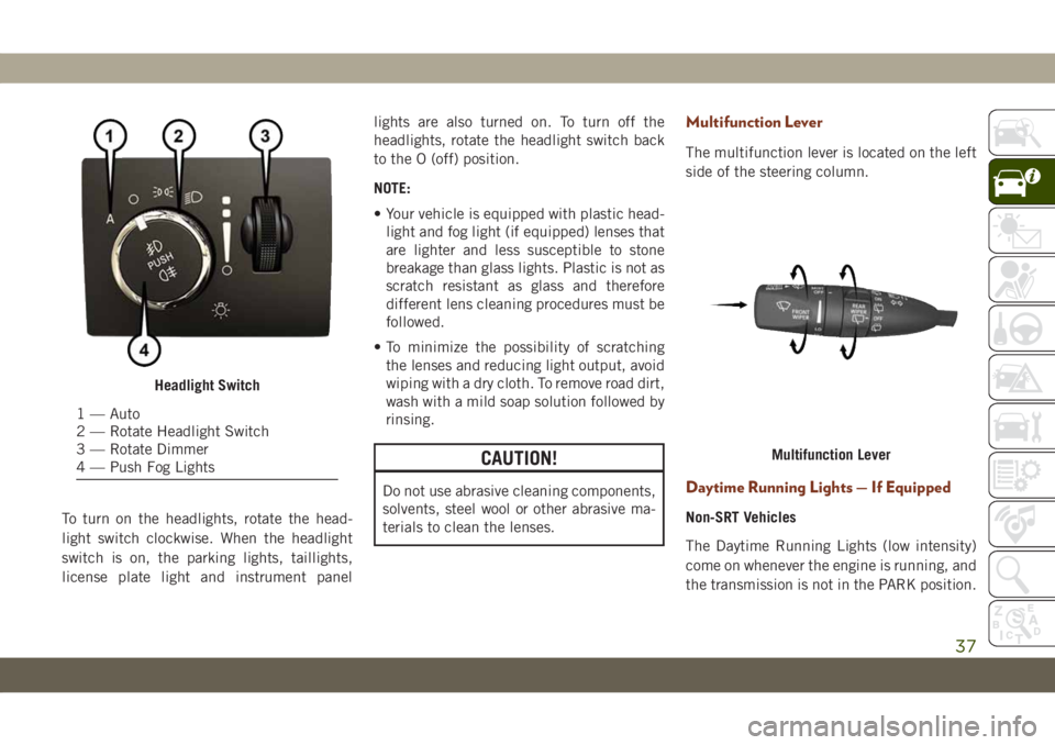
To turn on the headlights, rotate the head-
light switch clockwise. When the headlight
switch is on, the parking lights, taillights,
license plate light and instrument panellights are also turned on. To turn off the
headlights, rotate the headlight switch back
to the O (off) position.
NOTE:
• Your vehicle is equipped with plastic head-
light and fog light (if equipped) lenses that
are lighter and less susceptible to stone
breakage than glass lights. Plastic is not as
scratch resistant as glass and therefore
different lens cleaning procedures must be
followed.
• To minimize the possibility of scratching
the lenses and reducing light output, avoid
wiping with a dry cloth. To remove road dirt,
wash with a mild soap solution followed by
rinsing.
CAUTION!
Do not use abrasive cleaning components,
solvents, steel wool or other abrasive ma-
terials to clean the lenses.
Multifunction Lever
The multifunction lever is located on the left
side of the steering column.
Daytime Running Lights — If Equipped
Non-SRT Vehicles
The Daytime Running Lights (low intensity)
come on whenever the engine is running, and
the transmission is not in the PARK position.
Headlight Switch
1 — Auto
2 — Rotate Headlight Switch
3 — Rotate Dimmer
4 — Push Fog Lights
Multifunction Lever
37
Page 40 of 378
The lights will remain on until the ignition is
switched to the OFF or ACC position or the
parking brake is engaged.
NOTE:
• If a turn signal is activated, the DRL lamp
on the same side of the vehicle will turn off
for the duration of the turn signal activa-
tion. Once the turn signal is no longer
active, the DRL lamp will illuminate.
• The DRL function may be disabled through
the Uconnect system. Refer to “Uconnect
Settings” in “Multimedia” in the Owner’s
Manual for further information.
SRT Vehicles
The Daytime Running Lights (bright inten-
sity) come on whenever the engine is run-
ning, and the transmission is not in the PARK
position. The lights will remain on until the
ignition is switched to the OFF or ACC posi-
tion or the parking brake is engaged.
The headlight switch must be used for normal
nighttime driving.High/Low Beam Switch
Push the multifunction lever toward the in-
strument panel to switch the headlights to
high beams. Pulling the multifunction back
toward the steering wheel will turn the low
beams back on, or shut the high beams off.
Automatic High Beam — If Equipped
The Automatic High Beam Headlamp Control
system provides increased forward lighting at
night by automating high beam control
through the use of a digital camera mounted
on the inside rearview mirror. This camera
detects vehicle specific light and automati-
cally switches from high beams to low beams
until the approaching vehicle is out of view.
NOTE:
• The Automatic High Beam Headlamp Con-
trol can be turned on or off by selecting
“ON” under “Auto High Beam” within your
Uconnect settings, as well as turning the
headlight switch to the AUTO position. Re-
fer to “Uconnect Settings” in “Multime-
dia” in the Owner’s Manual for further in-
formation.• Broken, muddy, or obstructed headlights
and taillights of vehicles in the field of view
will cause headlights to remain on longer
(closer to the vehicle). Also, dirt, film, and
other obstructions on the windshield or
camera lens will cause the system to func-
tion improperly.
If the windshield or Automatic High Beam
Headlamp Control mirror is replaced, the
mirror must be re-aimed to ensure proper
performance. See a local authorized dealer.
Flash-To-Pass
You can signal another vehicle with your
headlights by lightly pulling the multifunc-
tion lever toward you. This will cause the high
beam headlights to turn on, and remain on,
until the lever is released.
Automatic Headlights — If Equipped
This system automatically turns the head-
lights on or off according to ambient light
levels. To turn the system on, rotate the
headlight switch to the A (auto) position.
GETTING TO KNOW YOUR VEHICLE
38
Page 41 of 378
When the system is on, the Headlight Delay
feature is also on. This means the headlights
will stay on for up to 90 seconds after you
turn the ignition switch to the OFF position.
To turn the automatic headlights off, turn the
headlight switch out of the A (auto) position.
NOTE:
The engine must be running before the head-
lights will turn on in the Automatic Mode.
Parking Lights And Panel Lights
To turn on the parking lights and instrument
panel lights, rotate the headlight switch
clockwise. To turn off the parking lights,
rotate the headlight switch back to the O (off)
position.
Headlights On Automatically With
Wipers
If your vehicle is equipped with Automatic
Headlights, it also has this customer-
programmable feature. When your headlights
are in the automatic mode and the engine is
running, they will automatically turn on when
the wiper system is on. This feature is pro-grammable through the Uconnect system
screen. Refer to “Uconnect Settings” in
“Multimedia” in the Owner’s Manual for fur-
ther information.
If your vehicle is equipped with a “Rain
Sensitive Wiper System” and it is activated,
the headlights will automatically turn on after
the wipers complete five wipe cycles within
approximately one minute, and they will turn
off approximately four minutes after the wip-
ers completely stop.
Refer to “Windshield Wipers And Washers” in
“Getting To Know Your Vehicle” for further
information.
NOTE:
When your headlights come on during the
daytime, the instrument panel lights will au-
tomatically dim to the lower nighttime inten-
sity.Adaptive Bi-Xenon High Intensity
Discharge Headlights — If Equipped
This system automatically swivels the head-
light beam pattern horizontally to provide
increased illumination in the direction the
vehicle is steering.NOTE:
• Each time the Adaptive Headlight System
is turned on, the headlights will initialize by
performing a brief sequence of rotations.
• The Adaptive Headlight System is active
only when the vehicle is moving forward.
The Adaptive Headlight System can be
turned on or off using the Uconnect System,
refer to “Uconnect Settings” in “Multime-
dia” in the Owner’s Manual for further infor-
mation.
Headlight Delay
To aid in your exit, your vehicle is equipped
with a headlight delay that will leave the
headlights on for approximately up to 90 sec-
onds. This delay is initiated when the ignition
is turned OFF while the headlight switch is
on, and then the headlight switch is cycled
off. Headlight delay can be cancelled by
either turning the headlight switch on then
off, or by turning the ignition ON.
39
Page 42 of 378
NOTE:
• This feature can be programmed through
the Uconnect system. Refer to “Uconnect
Settings” in “Multimedia” in the Owner’s
Manual for further information.
• The headlight delay feature is automati-
cally activated if the headlight switch is left
in the A (auto) position when the ignition is
placed in the OFF position.
Lights-On Reminder
If the headlights, parking lights, or cargo
lights are left on after the ignition is turned
OFF, a chime will sound when the driver’s
door is opened.
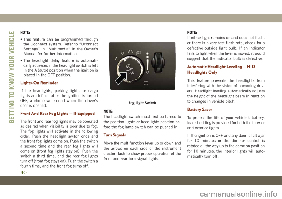
Front And Rear Fog Lights — If Equipped
The front and rear fog lights may be operated
as desired when visibility is poor due to fog.
The fog lights will activate in the following
order: Push the headlight switch once and
the front fog lights come on. Push the switch
a second time and the rear fog lights will
come on (front fog lights stay on). Push the
switch a third time, and the rear fog lights
turn off (front fog stays on). Push the switch a
fourth time, and the front fog turns off.NOTE:
The headlight switch must first be turned to
the position lights or headlights position be-
fore the fog lamp switch can be pushed in.
Turn Signals
Move the multifunction lever up or down and
the arrows on each side of the instrument
cluster flash to show proper operation of the
front and rear turn signal lights.NOTE:
If either light remains on and does not flash,
or there is a very fast flash rate, check for a
defective outside light bulb. If an indicator
fails to light when the lever is moved, it would
suggest that the indicator bulb is defective.
Automatic Headlight Leveling — HID
Headlights Only
This feature prevents the headlights from
interfering with the vision of oncoming driv-
ers. Headlight leveling automatically adjusts
the height of the headlight beam in reaction
to changes in vehicle pitch.
Battery Saver
To protect the life of your vehicle’s battery,
load shedding is provided for both the interior
and exterior lights.
If the ignition is OFF and any door is left ajar
for 10 minutes or the dimmer control is
rotated all the way up to the dome on position
for 10 minutes, the interior lights will auto-
matically turn off.
Fog Light Switch
GETTING TO KNOW YOUR VEHICLE
40
Page 43 of 378
NOTE:
Battery saver mode is canceled if the ignition
is ON.
If the headlights remain on while the ignition
is cycled OFF, the exterior lights will auto-
matically turn off after eight minutes. If the
headlights are turned on and left on for eight
minutes while the ignition is OFF, the exterior
lights will automatically turn off.
NOTE:
The battery saver mode is canceled if the
ignition is OFF and the headlamp switch is in
the park lamp position. The parking lamps
will remain on and drain the vehicle's battery.
WINDSHIELD WIPERS AND
WASHERS
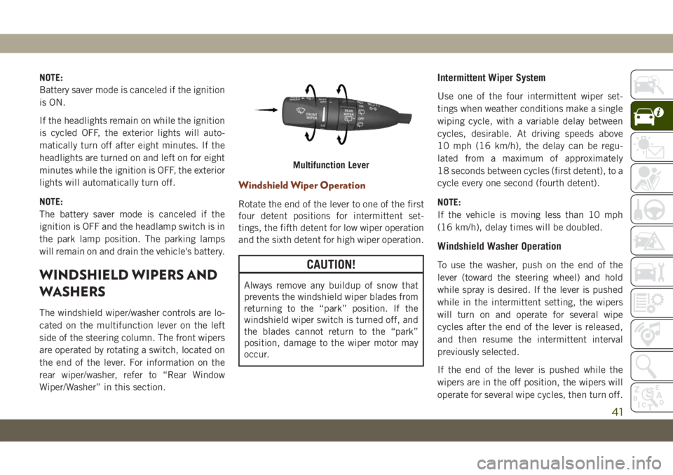
The windshield wiper/washer controls are lo-
cated on the multifunction lever on the left
side of the steering column. The front wipers
are operated by rotating a switch, located on
the end of the lever. For information on the
rear wiper/washer, refer to “Rear Window
Wiper/Washer” in this section.
Windshield Wiper Operation
Rotate the end of the lever to one of the first
four detent positions for intermittent set-
tings, the fifth detent for low wiper operation
and the sixth detent for high wiper operation.
CAUTION!
Always remove any buildup of snow that
prevents the windshield wiper blades from
returning to the “park” position. If the
windshield wiper switch is turned off, and
the blades cannot return to the “park”
position, damage to the wiper motor may
occur.
Intermittent Wiper System
Use one of the four intermittent wiper set-
tings when weather conditions make a single
wiping cycle, with a variable delay between
cycles, desirable. At driving speeds above
10 mph (16 km/h), the delay can be regu-
lated from a maximum of approximately
18 seconds between cycles (first detent), to a
cycle every one second (fourth detent).
NOTE:
If the vehicle is moving less than 10 mph
(16 km/h), delay times will be doubled.
Windshield Washer Operation
To use the washer, push on the end of the
lever (toward the steering wheel) and hold
while spray is desired. If the lever is pushed
while in the intermittent setting, the wipers
will turn on and operate for several wipe
cycles after the end of the lever is released,
and then resume the intermittent interval
previously selected.
If the end of the lever is pushed while the
wipers are in the off position, the wipers will
operate for several wipe cycles, then turn off.
Multifunction Lever
41
Page 51 of 378
Icon Description
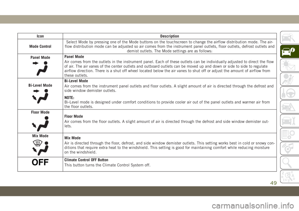
Mode ControlSelect Mode by pressing one of the Mode buttons on the touchscreen to change the airflow distribution mode. The air-
flow distribution mode can be adjusted so air comes from the instrument panel outlets, floor outlets, defrost outlets and
demist outlets. The Mode settings are as follows:
Panel Mode
Panel Mode
Air comes from the outlets in the instrument panel. Each of these outlets can be individually adjusted to direct the flow
of air. The air vanes of the center outlets and outboard outlets can be moved up and down or side to side to regulate
airflow direction. There is a shut off wheel located below the air vanes to shut off or adjust the amount of airflow from
these outlets.
Bi-Level Mode
Bi-Level Mode
Air comes from the instrument panel outlets and floor outlets. A slight amount of air is directed through the defrost and
side window demister outlets.
NOTE:
Bi-Level mode is designed under comfort conditions to provide cooler air out of the panel outlets and warmer air from
the floor outlets.
Floor Mode
Floor Mode
Air comes from the floor outlets. A slight amount of air is directed through the defrost and side window demister out-
lets.
Mix Mode
Mix Mode
Air is directed through the floor, defrost, and side window demister outlets. This setting works best in cold or snowy con-
ditions that require extra heat to the windshield. This setting is good for maintaining comfort while reducing moisture
on the windshield.
Climate Control OFF Button
This button turns the Climate Control System off.
49
Page 55 of 378
Push the window switch down for half a
second and release. The window will go down
automatically.
To stop the window from going all the way
down during the Auto-Down operation, pull
up or push down on the switch briefly.
To open the window part way (manually),
push the window switch down briefly and
release.
Auto-Up Feature With Anti-Pinch
Protection
NOTE:
• If the window runs into any obstacle during
auto-closure, it will reverse direction and
then go back down. Remove the obstacle
and use the window switch again to close
the window.
• Any impact due to rough road conditions
may trigger the auto-reverse function unex-
pectedly during auto-closure. If this hap-
pens, pull the switch lightly and hold to
close the window manually.
WARNING!
There is no anti-pinch protection when the
window is almost closed. To avoid personal
injury be sure to clear your arms, hands,
fingers and all objects from the window
path before closing.
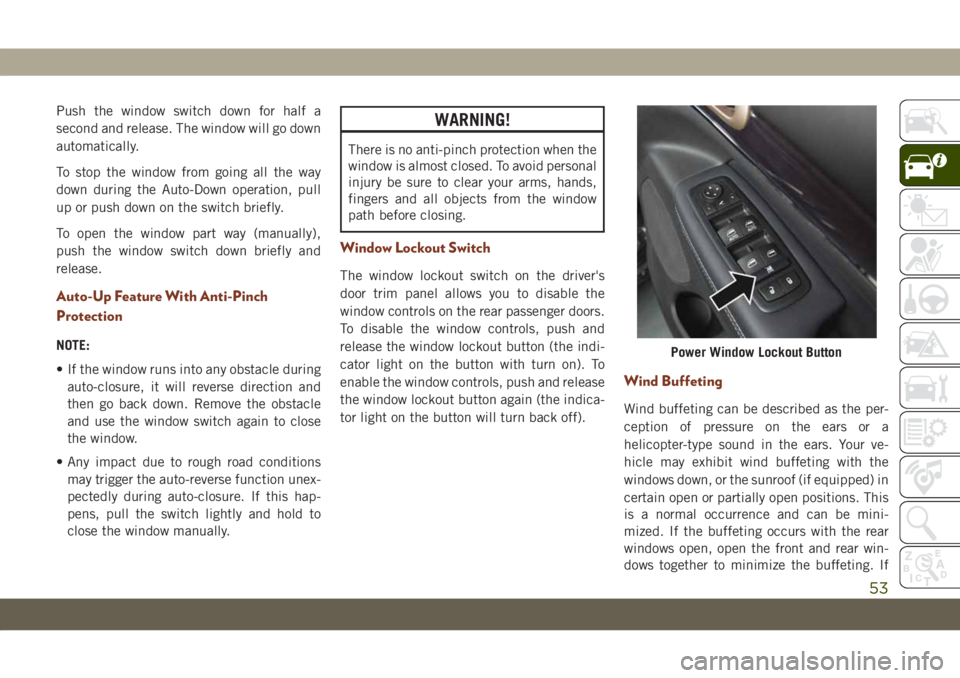
Window Lockout Switch
The window lockout switch on the driver's
door trim panel allows you to disable the
window controls on the rear passenger doors.
To disable the window controls, push and
release the window lockout button (the indi-
cator light on the button with turn on). To
enable the window controls, push and release
the window lockout button again (the indica-
tor light on the button will turn back off).
Wind Buffeting
Wind buffeting can be described as the per-
ception of pressure on the ears or a
helicopter-type sound in the ears. Your ve-
hicle may exhibit wind buffeting with the
windows down, or the sunroof (if equipped) in
certain open or partially open positions. This
is a normal occurrence and can be mini-
mized. If the buffeting occurs with the rear
windows open, open the front and rear win-
dows together to minimize the buffeting. If
Power Window Lockout Button
53
Page 64 of 378
• The power liftgate will not operate in tem-
peratures below −22°F (−30°C) or tem-
peratures above 150° F (65° C). Be sure to
remove any buildup of snow or ice from the
liftgate before pushing any of the power
liftgate switches.
• If anything obstructs the power liftgate
while it is closing or opening, the liftgate
will automatically reverse to the closed or
open position, provided it meets sufficient
resistance.
• There are also pinch sensors attached to
the side of the liftgate. Light pressure any-
where along these strips will cause the
liftgate to return to the open position.
• If the liftgate is not fully open, push the
liftgate button on the key fob twice to
operate the liftgate.
• If the electronic liftgate release is pushed
while the power liftgate is closing, the lift-
gate will reverse to the full open position.• If the electronic liftgate release is pushed
while the power liftgate is opening, the
liftgate motor will disengage to allow
manual operation.
• If the power liftgate encounters multiple
obstructions within the same cycle, the
system will automatically stop and the lift-
gate must be opened or closed manually.
WARNING!
• Driving with the liftgate open can allow
poisonous exhaust gases into your ve-
hicle. You and your passengers could be
injured by these fumes. Keep the liftgate
closed when you are operating the
vehicle.
• If you are required to drive with the
liftgate open, make sure that all win-
dows are closed, and the climate control
blower switch is set at high speed. Do
not use the recirculation mode.
INTERNAL EQUIPMENT
Power Outlets
If equipped, there may be three 12 Volt
electrical power outlets on this vehicle.
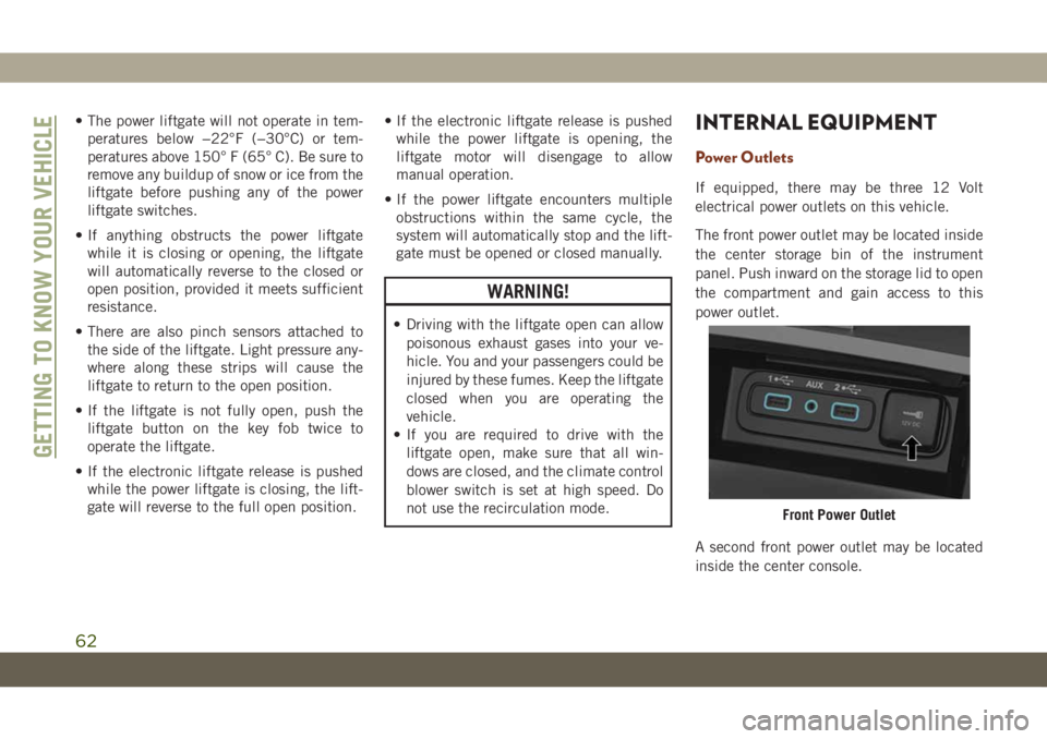
The front power outlet may be located inside
the center storage bin of the instrument
panel. Push inward on the storage lid to open
the compartment and gain access to this
power outlet.
A second front power outlet may be located
inside the center console.
Front Power Outlet
GETTING TO KNOW YOUR VEHICLE
62
Page 66 of 378
CAUTION!
• Power outlets are designed for accessory
plugs only. Do not insert any other object
in the power outlets as this will damage
the outlet and blow the fuse. Improper
use of the power outlet can cause dam-
age not covered by your New Vehicle
Limited Warranty.
WARNING!
To avoid serious injury or death:
• Do not insert any objects into the
receptacles.
• Do not touch with wet hands.
• Close the lid when not in use.
• If this outlet is mishandled, it may
cause an electric shock and failure.
CAUTION!
•Many accessories that can be plugged in
draw power from the vehicle's battery, even
when not in use (i.e., cellular phones,
etc.). Eventually, if plugged in long
enough, the vehicle's battery will discharge
sufficiently to degrade battery life and/or
prevent the engine from starting.
• Accessories that draw higher power (i.e.,
coolers, vacuum cleaners, lights, etc.),
will degrade the battery even more
quickly. Only use these intermittently
and with greater caution.
• After the use of high power draw acces-
sories, or long periods of the vehicle not
being started (with accessories still
plugged in), the vehicle must be driven a
sufficient length of time to allow the
alternator to recharge the vehicle's
battery.
• Power outlets are designed for accessory
plugs only. Do not hang any type of
accessory or accessory bracket from the
plug. Improper use of the power outlet
can cause damage.
ROOF LUGGAGE RACK — IF
EQUIPPED
The crossbars and siderails are designed to
carry the weight on vehicles equipped with a
luggage rack. The load must not exceed
150 lbs (68 kg), and should be uniformly
distributed over the luggage rack crossbars.
NOTE:
If not equipped with crossbars, your autho-
rized dealer can order and install Mopar
crossbars built specifically for this roof rack
system.
Distribute cargo weight evenly on the roof
rack crossbars. The roof rack does not in-
crease the total load carrying capacity of the
vehicle. Be sure the total load of cargo inside
the vehicle plus that on the external rack
does not exceed the maximum vehicle load
capacity.
To move the crossbars, loosen the attach-
ments, located at the upper edge of each
crossbar, approximately eight turns using the
anti-theft wrench provided with the Mopar
crossbars. Then, move the crossbar to the
desired position, keeping the crossbars par-
GETTING TO KNOW YOUR VEHICLE
64
Page 71 of 378
• Engine Will Not Restart in XXX mi Service
AdBlue®See Dealer
• Engine Will Not Restart Service AdBlue
®
System See Dealer
• Engine Will Not Start Service AdBlue
®Sys-
tem See Dealer
Diesel Particulate Filter (DPF) Messages
— If Equipped
This engine meets all required diesel engine
emissions standards. To achieve these emis-
sions standards, your vehicle is equipped
with a state-of-the-art engine and exhaust
system. These systems are seamlessly inte-
grated into your vehicle and managed by the
Powertrain Control Module (PCM). The PCM
manages engine combustion to allow the ex-
haust system’s catalyst to trap and burn Par-
ticulate Matter (PM) pollutants, with no input
or interaction on your part.
WARNING!
A hot exhaust system can start a fire if you
park over materials that can burn. Such
materials might be grass or leaves coming
WARNING!
into contact with your exhaust system. Do
not park or operate your vehicle in areas
where your exhaust system can contact
anything that can burn.
Your vehicle has the ability to alert you to
additional maintenance required on your ve-
hicle or engine. Refer to the following mes-
sages that may be displayed on your instru-
ment cluster display:
•Exhaust Filter Nearing Full Safely Drive at
Highway Speeds to Clear— This message
will be displayed if the exhaust particulate
filter reaches 80% of its maximum storage
capacity. Under conditions of exclusive
short duration and low speed driving cycles,
your diesel engine and exhaust after-
treatment system may never reach the con-
ditions required to cleanse the filter to
remove the trapped PM. If this occurs, the
“Exhaust Filter XX% Full Safely Drive at
Highway Speeds to Remedy” message will
be displayed. If this message is displayed,
you will hear one chime to assist in alerting
you of this condition. By simply driving yourvehicle at highway speeds for up to 20 min-
utes, you can remedy the condition in the
particulate filter system and allow your die-
sel engine and exhaust after-treatment sys-
tem to cleanse the filter to remove the
trapped PM and restore the system to nor-
mal operating condition.
•Exhaust System Regeneration in Process Con-
tinue Driving— This message indicates that
the Diesel Particulate Filter (DPF) is self-
cleaning. Maintain your current driving
condition until regeneration is completed.
•Exhaust System — Regeneration Completed
— This message indicates that the Diesel
Particulate Filter (DPF) self-cleaning is
completed. If this message is displayed,
you will hear one chime to assist in alerting
you of this condition.
•Exhaust System Service Required — See
Dealer— This messages indicates regen-
eration has been disabled due to a system
malfunction. At this point the engine Pow-
ertrain Control Module (PCM) will register a
fault code, the instrument panel will dis-
play a MIL light.
69