Ignition switch JEEP GRAND CHEROKEE 2020 Owner handbook (in English)
[x] Cancel search | Manufacturer: JEEP, Model Year: 2020, Model line: GRAND CHEROKEE, Model: JEEP GRAND CHEROKEE 2020Pages: 378, PDF Size: 6.88 MB
Page 184 of 378
When both lane markings are detected and
the driver unintentionally drifts out of the
lane (no turn signal applied), the LaneSense
system provides a haptic warning in the form
of torque applied to the steering wheel to
prompt the driver to remain within the lane
boundaries. If the driver continues to unin-
tentionally drift out of the lane, the Lane-
Sense system provides a visual warning
through the instrument cluster display to
prompt the driver to remain within the lane
boundaries.
The driver may manually override the haptic
warning by applying torque into the steering
wheel at any time.
When only a single lane marking is detected
and the driver unintentionally drifts across
the lane marking (no turn signal applied), the
LaneSense system provides visual warnings
through the instrument cluster display to
prompt the driver to remain within the lane.
When only a single lane marking is detected,
a haptic (torque) warning will not be
provided.NOTE:
When operating conditions have been met,
the LaneSense system will monitor if the
driver’s hands are on the steering wheel and
provides an audible warning to the driver
when the driver’s hands are not detected on
the steering wheel. The system will cancel if
the driver does not return their hands to the
wheel.
Turning LaneSense On Or Off
The default status of LaneSense is off. The
LED in LaneSense button will be illuminated
while the system is deactivated.
The LaneSense button is located
on the switch panel below the
Uconnect display.
To turn the LaneSense system
on, push the LaneSense button (LED turns
off). A “LaneSense On” message is shown in
the instrument cluster display.
To turn the LaneSense system off, push the
LaneSense button once (LED turns on).NOTE:
The LaneSense system will retain the last
system state on or off from the last ignition
cycle when the ignition is changed to the
ON/RUN position.
LaneSense Warning Message
The LaneSense system will indicate the cur-
rent lane drift condition through the instru-
ment cluster display.
Premium Instrument Cluster Display
When the LaneSense system is on; the lane
lines are gray when both of the lane bound-
aries have not been detected and the Lane-
Sense telltale
is solid white.
Left Lane Departure — Only Left Lane Detected
• When the LaneSense system is on, the
LaneSense telltale
is solid white when
only the left lane marking has been de-
tected and the system is ready to provide
visual warnings in the instrument cluster
display if an unintentional lane departure
occurs.
STARTING AND OPERATING
182
Page 194 of 378
• If containers which can be screwed to the
filler are used, the reservoir is full when the
AdBlue
®level in the container stops pour-
ing out. Do not proceed further.
CAUTION!
To avoid fuel spillage and overfilling, do
not “top off” the fuel tank after filling.
Operations After Refilling
Proceed as follows:
• Fit the cap back on the AdBlue
®filler by
turning it clockwise and screwing it com-
pletely.
• Cycle the ignition to RUN (it is not neces-
sary to start the engine).
• Wait for the indication on the instrument
panel to switch off before moving the car.
The indication may stay on for a few sec-
onds to approximately half a minute. If the
engine is started and the car is moved, the
indication will remain on for longer. This
will not compromise engine operation.• If the AdBlue
®was topped up when the
tank was empty, wait for 2 minutes before
starting the engine.
NOTE:
• If AdBlue
®is spilled out of the filler neck,
clean up well the area and proceed to filling
up again. If the liquid crystallizes, elimi-
nate it with a sponge and warm water.
• DO NOT EXCEED THE MAXIMUM LEVEL:
this could cause damage to the reservoir.
AdBlue
®freezes at under 12° F (-11° C).
Although the system is designed to operate
below the freezing point of the AdBlue
®,it
is advisable not to fill the tank beyond the
maximum level because if the AdBlue
®
freezes the system can be damaged. Follow
the instructions in this section.
• If the AdBlue
®is spilled on painted sur-
faces or aluminium, immediately clean the
area with water and use absorbent material
to collect the fluid that has been spilled on
the ground.
• Do not try to start the engine if AdBlue
®
was accidentally added to the diesel fuel
tank, this can result in serious engine dam-
age, contact an authorized dealer.• Do not add additives or other fluids to
AdBlue
®, doing so could damage the
system.
• The use of non-conforming or degraded
AdBlue
®may lead to indications appearing
on the instrument panel display refer to
“Warning Lights And Messages" in the
“Getting To Know Your Instrument Panel”
for further information.
• Never pour AdBlue
®into another con-
tainer: it could be contaminated.
• If the AdBlue
®runs out, see refer to “Warn-
ing Lights And Messages" in the “Getting To
Know Your Instrument Panel” for further
information to continue using the car
normally.
TRAILER TOWING
Trailer Towing Weights (Maximum Trailer
Weight Ratings) — Non SRT
The following chart provides the maximum
trailer weight ratings towable for your given
drivetrain.
STARTING AND OPERATING
192
Page 203 of 378
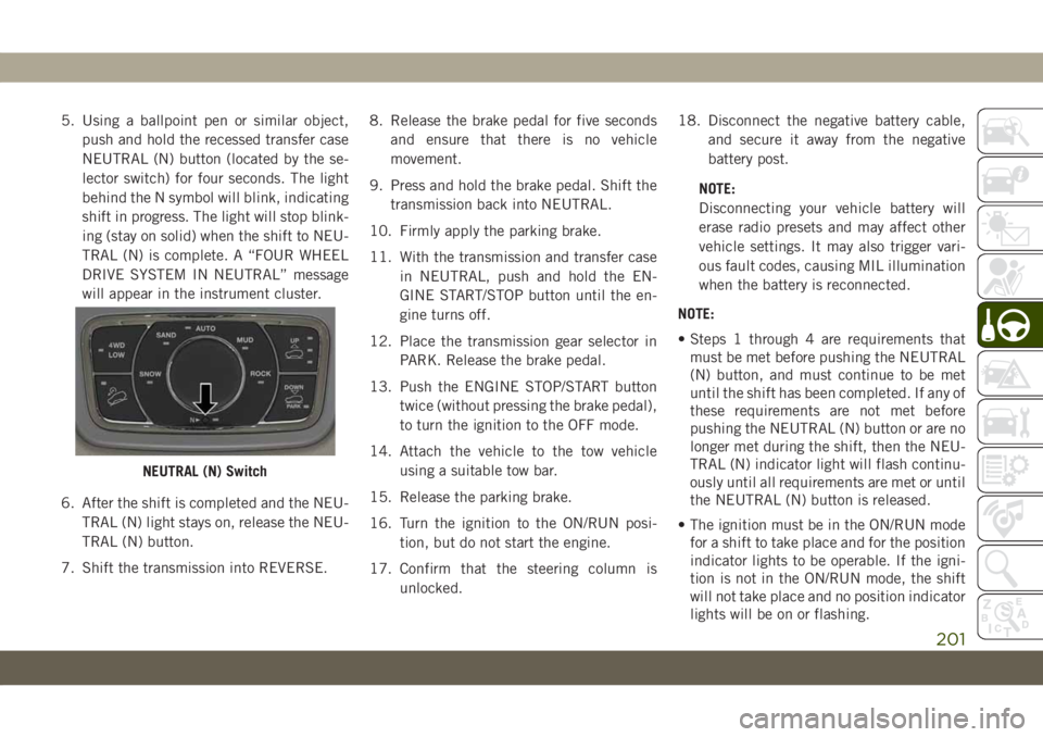
5. Using a ballpoint pen or similar object,
push and hold the recessed transfer case
NEUTRAL (N) button (located by the se-
lector switch) for four seconds. The light
behind the N symbol will blink, indicating
shift in progress. The light will stop blink-
ing (stay on solid) when the shift to NEU-
TRAL (N) is complete. A “FOUR WHEEL
DRIVE SYSTEM IN NEUTRAL” message
will appear in the instrument cluster.
6. After the shift is completed and the NEU-
TRAL (N) light stays on, release the NEU-
TRAL (N) button.
7. Shift the transmission into REVERSE.8. Release the brake pedal for five seconds
and ensure that there is no vehicle
movement.
9. Press and hold the brake pedal. Shift the
transmission back into NEUTRAL.
10. Firmly apply the parking brake.
11. With the transmission and transfer case
in NEUTRAL, push and hold the EN-
GINE START/STOP button until the en-
gine turns off.
12. Place the transmission gear selector in
PARK. Release the brake pedal.
13. Push the ENGINE STOP/START button
twice (without pressing the brake pedal),
to turn the ignition to the OFF mode.
14. Attach the vehicle to the tow vehicle
using a suitable tow bar.
15. Release the parking brake.
16. Turn the ignition to the ON/RUN posi-
tion, but do not start the engine.
17. Confirm that the steering column is
unlocked.18. Disconnect the negative battery cable,
and secure it away from the negative
battery post.
NOTE:
Disconnecting your vehicle battery will
erase radio presets and may affect other
vehicle settings. It may also trigger vari-
ous fault codes, causing MIL illumination
when the battery is reconnected.
NOTE:
• Steps 1 through 4 are requirements that
must be met before pushing the NEUTRAL
(N) button, and must continue to be met
until the shift has been completed. If any of
these requirements are not met before
pushing the NEUTRAL (N) button or are no
longer met during the shift, then the NEU-
TRAL (N) indicator light will flash continu-
ously until all requirements are met or until
the NEUTRAL (N) button is released.
• The ignition must be in the ON/RUN mode
for a shift to take place and for the position
indicator lights to be operable. If the igni-
tion is not in the ON/RUN mode, the shift
will not take place and no position indicator
lights will be on or flashing.
NEUTRAL (N) Switch
201
Page 204 of 378
• A flashing NEUTRAL (N) position indicator
light indicates that shift requirements have
not been met.
• If the vehicle is equipped with Quadra-Lift
air suspension, the engine should be
started and left running for a minimum of
60 seconds (with all the doors closed) at
least once every 24 hours. This process
allows the air suspension to adjust the
vehicle’s ride height to compensate for
temperature effects.
Shifting Out Of NEUTRAL (N)
Use the following procedure to prepare your
vehicle for normal usage.
1. Bring the vehicle to a complete stop,
leaving it connected to the tow vehicle.
2. Firmly apply the parking brake.
3. Reconnect the negative battery cable.
4. Turn the ignition to the LOCK/OFF mode.
5. Start the engine.
6. Press and hold the brake pedal.
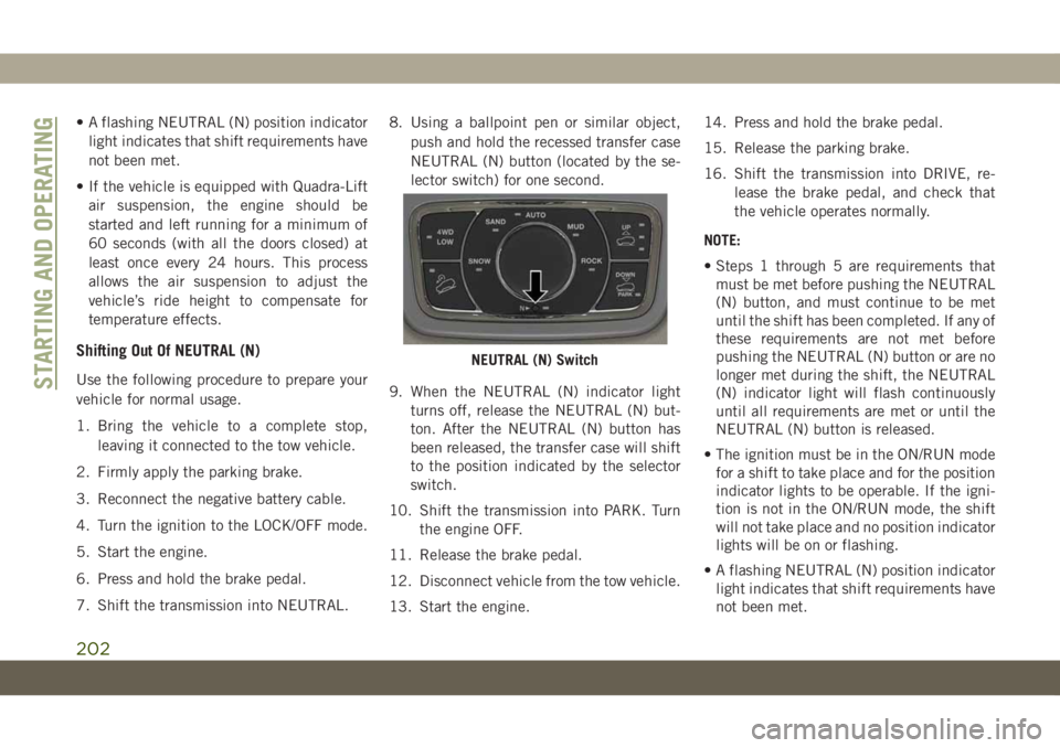
7. Shift the transmission into NEUTRAL.8. Using a ballpoint pen or similar object,
push and hold the recessed transfer case
NEUTRAL (N) button (located by the se-
lector switch) for one second.
9. When the NEUTRAL (N) indicator light
turns off, release the NEUTRAL (N) but-
ton. After the NEUTRAL (N) button has
been released, the transfer case will shift
to the position indicated by the selector
switch.
10. Shift the transmission into PARK. Turn
the engine OFF.
11. Release the brake pedal.
12. Disconnect vehicle from the tow vehicle.
13. Start the engine.14. Press and hold the brake pedal.
15. Release the parking brake.
16. Shift the transmission into DRIVE, re-
lease the brake pedal, and check that
the vehicle operates normally.
NOTE:
• Steps 1 through 5 are requirements that
must be met before pushing the NEUTRAL
(N) button, and must continue to be met
until the shift has been completed. If any of
these requirements are not met before
pushing the NEUTRAL (N) button or are no
longer met during the shift, the NEUTRAL
(N) indicator light will flash continuously
until all requirements are met or until the
NEUTRAL (N) button is released.
• The ignition must be in the ON/RUN mode
for a shift to take place and for the position
indicator lights to be operable. If the igni-
tion is not in the ON/RUN mode, the shift
will not take place and no position indicator
lights will be on or flashing.
• A flashing NEUTRAL (N) position indicator
light indicates that shift requirements have
not been met.
NEUTRAL (N) Switch
STARTING AND OPERATING
202
Page 205 of 378
HAZARD WARNING
FLASHERS
The Hazard Warning flasher switch is located
on the switch bank just above the climate
controls.
Push the switch to turn on the
Hazard Warning flasher. When the
switch is activated, all directional
turn signals will flash on and off to
warn oncoming traffic of an emergency. Push
the switch a second time to turn off the
Hazard Warning flashers.This is an emergency warning system and it
should not be used when the vehicle is in
motion. Use it when your vehicle is disabled
and it is creating a safety hazard for other
motorists.
When you must leave the vehicle to seek
assistance, the Hazard Warning flashers will
continue to operate even though the ignition
is placed in the OFF position.
NOTE:
With extended use, the Hazard Warning
flashers may discharge the battery.
203
Page 212 of 378
FUSES
WARNING!
•When replacing a blown fuse, always use
an appropriate replacement fuse with the
same amp rating as the original fuse. Never
replace a fuse with another fuse of higher
amp rating. Never replace a blown fuse
with metal wires or any other material. Do
not place a fuse inside a circuit breaker
cavity or vice versa. Failure to use proper
fuses may result in serious personal injury,
fire and/or property damage.
•Before replacing a fuse, make sure that the
ignition is off and that all the other services
are switched off and/or disengaged.
•If the replaced fuse blows again, contact
an authorized dealer.
•If a general protection fuse for safety sys-
tems (air bag system, braking system),
power unit systems (engine system, trans-
mission system) or steering system blows,
contact an authorized dealer.
CAUTION!
If it is necessary to wash the engine com-
partment, take care not to directly hit the
fuse box, and the windshield wiper motors
with water.
General Information
The fuses protect electrical systems against
excessive current.
When a device does not work, you must check
the fuse element inside the blade fuse for a
break/melt.
Also, please be aware that when using power
outlets for extended periods of time with the
engine off may result in vehicle battery dis-
charge.
Underhood Fuses
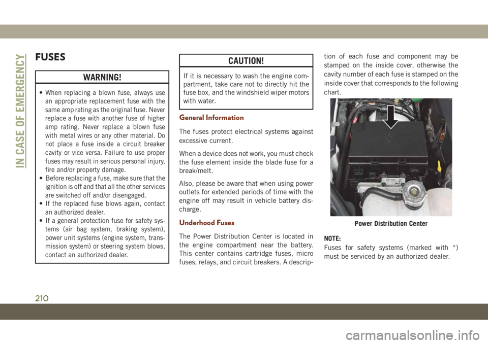
The Power Distribution Center is located in
the engine compartment near the battery.
This center contains cartridge fuses, micro
fuses, relays, and circuit breakers. A descrip-tion of each fuse and component may be
stamped on the inside cover, otherwise the
cavity number of each fuse is stamped on the
inside cover that corresponds to the following
chart.
NOTE:
Fuses for safety systems (marked with *)
must be serviced by an authorized dealer.
Power Distribution Center
IN CASE OF EMERGENCY
210
Page 228 of 378
WARNING!
Do not attempt jump starting if the battery
is frozen. It could rupture or explode and
cause personal injury.
CAUTION!
Do not use a portable battery booster pack
or any other booster source with a system
voltage greater than 12 Volts or damage to
the battery, starter motor, alternator or
electrical system may occur.
NOTE:
When using a portable battery booster pack,
follow the manufacturer's operating instruc-
tions and precautions.
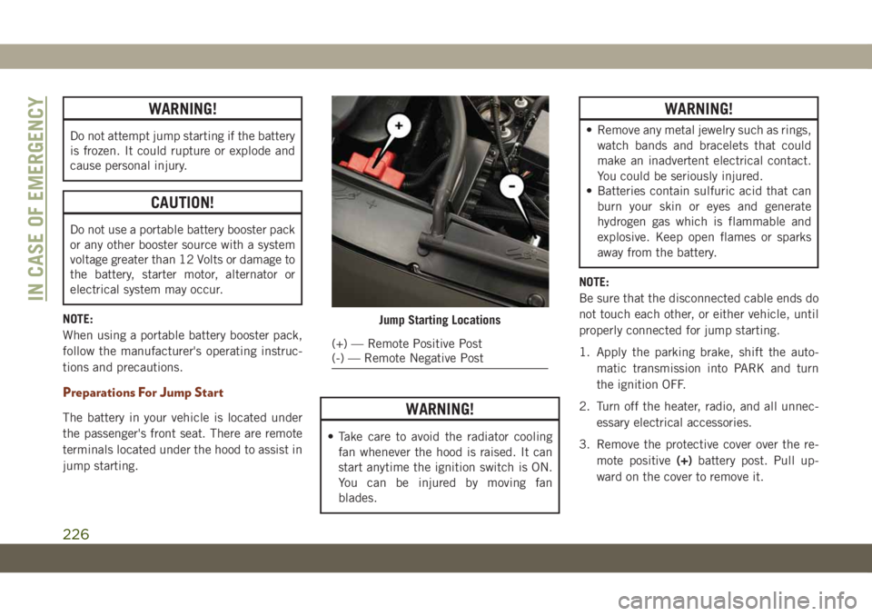
Preparations For Jump Start
The battery in your vehicle is located under
the passenger's front seat. There are remote
terminals located under the hood to assist in
jump starting.WARNING!
• Take care to avoid the radiator cooling
fan whenever the hood is raised. It can
start anytime the ignition switch is ON.
You can be injured by moving fan
blades.
WARNING!
• Remove any metal jewelry such as rings,
watch bands and bracelets that could
make an inadvertent electrical contact.
You could be seriously injured.
• Batteries contain sulfuric acid that can
burn your skin or eyes and generate
hydrogen gas which is flammable and
explosive. Keep open flames or sparks
away from the battery.
NOTE:
Be sure that the disconnected cable ends do
not touch each other, or either vehicle, until
properly connected for jump starting.
1. Apply the parking brake, shift the auto-
matic transmission into PARK and turn
the ignition OFF.
2. Turn off the heater, radio, and all unnec-
essary electrical accessories.
3. Remove the protective cover over the re-
mote positive(+)battery post. Pull up-
ward on the cover to remove it.
Jump Starting Locations
(+) — Remote Positive Post
(-) — Remote Negative Post
IN CASE OF EMERGENCY
226
Page 234 of 378
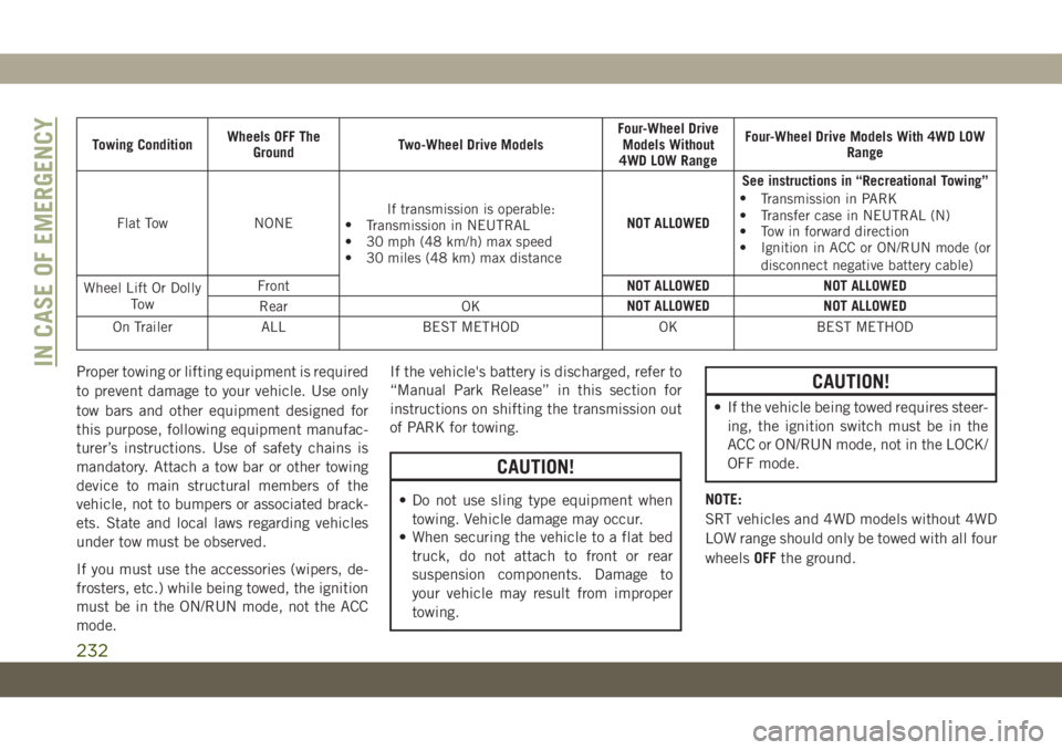
Towing ConditionWheels OFF The
GroundTwo-Wheel Drive ModelsFour-Wheel Drive
Models Without
4WD LOW RangeFour-Wheel Drive Models With 4WD LOW
Range
Flat Tow NONEIf transmission is operable:
•
Transmission in NEUTRAL
• 30 mph (48 km/h) max speed
• 30 miles (48 km) max distanceNOT ALLOWEDSee instructions in “Recreational Towing”
•
Transmission in PARK
• Transfer case in NEUTRAL (N)
• Tow in forward direction
• Ignition in ACC or ON/RUN mode (or
disconnect negative battery cable)
Wheel Lift Or Dolly
To wFrontNOT ALLOWED NOT ALLOWED
Rear OKNOT ALLOWED NOT ALLOWED
On Trailer ALL BEST METHOD OK BEST METHOD
Proper towing or lifting equipment is required
to prevent damage to your vehicle. Use only
tow bars and other equipment designed for
this purpose, following equipment manufac-
turer’s instructions. Use of safety chains is
mandatory. Attach a tow bar or other towing
device to main structural members of the
vehicle, not to bumpers or associated brack-
ets. State and local laws regarding vehicles
under tow must be observed.
If you must use the accessories (wipers, de-
frosters, etc.) while being towed, the ignition
must be in the ON/RUN mode, not the ACC
mode.If the vehicle's battery is discharged, refer to
“Manual Park Release” in this section for
instructions on shifting the transmission out
of PARK for towing.
CAUTION!
• Do not use sling type equipment when
towing. Vehicle damage may occur.
• When securing the vehicle to a flat bed
truck, do not attach to front or rear
suspension components. Damage to
your vehicle may result from improper
towing.
CAUTION!
• If the vehicle being towed requires steer-
ing, the ignition switch must be in the
ACC or ON/RUN mode, not in the LOCK/
OFF mode.
NOTE:
SRT vehicles and 4WD models without 4WD
LOW range should only be towed with all four
wheelsOFFthe ground.
IN CASE OF EMERGENCY
232
Page 276 of 378
system, thus minimizing the possibility of
damage to the compressor when the vehicle
is put back into operation.
NOTE:
When the vehicle has not been started or
driven for at least 30 days, an Extended Park
Start Procedure is required to start the ve-
hicle.
Refer to “Starting The Engine” in “Starting
And Operating” for further information.
CAUTION!
Before removal of the positive and nega-
tive terminals to the battery, wait at least a
minute with ignition switch in the OFF
position and close the driver’s door. When
reconnecting the positive and negative ter-
minals to the battery be sure the ignition
switch is in the OFF position and the
driver’s door is closed.
BODYWORK
Preserving The Bodywork
Washing
• Wash your vehicle regularly. Always wash
your vehicle in the shade using a mild car
wash soap, and rinse the panels completely
with clear water.
• If insects, tar, or other similar deposits have
accumulated on your vehicle, use a specific
detergent to remove.
• Use a high quality cleaner wax to remove
road film, stains and to protect your paint
finish. Take care never to scratch the paint.
• Avoid using abrasive compounds and power
buffing that may diminish the gloss or thin
out the paint finish.
CAUTION!
• Do not use abrasive or strong cleaning
materials such as steel wool or scouring
powder that will scratch metal and
painted surfaces.
CAUTION!
• Use of power washers exceeding
1,200 psi (8,274 kPa) can result in
damage or removal of paint and decals.
Special Care
• If you drive on salted or dusty roads or if you
drive near the ocean, hose off the undercar-
riage at least once a month.
• It is important that the drain holes in the
lower edges of the doors, rocker panels, and
trunk be kept clear and open.
• If you detect any stone chips or scratches in
the paint, touch them up immediately. The
cost of such repairs is considered the re-
sponsibility of the owner.
• If your vehicle is damaged due to a collision
or similar cause that destroys the paint and
protective coating, have your vehicle re-
paired as soon as possible. The cost of such
repairs is considered the responsibility of
the owner.
SERVICING AND MAINTENANCE
274
Page 372 of 378
Ignition.....................15
Switch...................15
Instrument Cluster..............67
Descriptions................83
Display...................66
Instrument Panel Lens Cleaning.....276
Interior Appearance Care.........275
Intermittent Wipers (Delay Wipers)....41
Introduction...................1
Jacking Instructions............218
Jack Location................217
Jack Operation.........217, 218, 262
Jump Starting................225
Key Fob
Arm The System.............18
Disarm The System............18
Keyless Enter-N-Go..............21
Passive Entry...............21
Keys.......................14
Replacement...............15
LaneSense..................181
Lap/Shoulder Belts.............110
Latches....................143
Hood....................59Lead Free Gasoline.............282
Leaks, Fluid.................143
Life Of Tires.................266
Liftgate.....................59
Closing...................60
Opening..................59
Power....................61
Liftgate Window Wiper/Washer.......43
Light Bulbs..................143
Lights.....................143
AirBag ............73, 117, 141
Automatic Headlights..........38
Brake Assist Warning...........92
Brake Warning...............73
Bulb Replacement...........204
Cruise.................82, 84
Daytime Running.............37
Electronic Stability Program(ESP)
Indicator..................75
Exterior..............
.36, 143
F
og ...................40, 81
Hazard Warning Flasher........203
Headlights On With Wipers.......39
High Beam/Low Beam Select . . .37, 38
Hill Descent Control Indicator.....94
Lights On Reminder...........40
Low Fuel..................77Malfunction Indicator
(Check Engine)..............78
Park..................39, 82
Passing...................38
Seat Belt Reminder...........75
Security Alarm..............76
Service..................204
Side Marker...............207
Traction Control..............92
Turn Signals......40, 83, 143, 207
Warning Instrument Cluster
Descriptions.............75, 83
Locks
Child Protection..............24
Luggage Carrier................64
Lug Nuts/Bolts................278
Maintenance...............55, 58
Maintenance Free Battery.........256
Maintenance Schedule. . . .236, 240, 244
Malfunction Indicator Light
(Check Engine)...............78
Memory Feature (Memory Seats)......25
Memory Seat..................25
Methanol...................283
Methanol Fuel................283
Mirrors.....................35
INDEX
370