clock JEEP GRAND CHEROKEE 2023 Owners Manual
[x] Cancel search | Manufacturer: JEEP, Model Year: 2023, Model line: GRAND CHEROKEE, Model: JEEP GRAND CHEROKEE 2023Pages: 424, PDF Size: 15.48 MB
Page 60 of 424
58GETTING TO KNOW YOUR VEHICLE
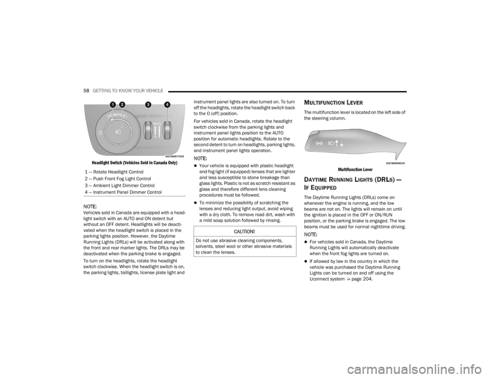
Headlight Switch (Vehicles Sold In Canada Only)
NOTE:Vehicles sold in Canada are equipped with a head -
light switch with an AUTO and ON detent but
without an OFF detent. Headlights will be deacti -
vated when the headlight switch is placed in the
parking lights position. However, the Daytime
Running Lights (DRLs) will be activated along with
the front and rear marker lights. The DRLs may be
deactivated when the parking brake is engaged.
To turn on the headlights, rotate the headlight
switch clockwise. When the headlight switch is on,
the parking lights, taillights, license plate light and instrument panel lights are also turned on. To turn
off the headlights, rotate the headlight switch back
to the O (off) position.
For vehicles sold in Canada, rotate the headlight
switch clockwise from the parking lights and
instrument panel lights position to the AUTO
position for automatic headlights. Rotate to the
second detent to turn on headlights, parking lights,
and instrument panel lights operation.
NOTE:
Your vehicle is equipped with plastic headlight
and fog light (if equipped) lenses that are lighter
and less susceptible to stone breakage than
glass lights. Plastic is not as scratch resistant as
glass and therefore different lens cleaning
procedures must be followed.
To minimize the possibility of scratching the
lenses and reducing light output, avoid wiping
with a dry cloth. To remove road dirt, wash with
a mild soap solution followed by rinsing.
MULTIFUNCTION LEVER
The multifunction lever is located on the left side of
the steering column.
Multifunction Lever
DAYTIME RUNNING LIGHTS (DRLS) —
I
F EQUIPPED
The Daytime Running Lights (DRLs) come on
whenever the engine is running, and the low
beams are not on. The lights will remain on until
the ignition is placed in the OFF or ON/RUN
position, or the parking brake is engaged. The low
beams must be used for normal nighttime driving.
NOTE:
For vehicles sold in Canada, the Daytime
Running Lights will automatically deactivate
when the front fog lights are turned on.
If allowed by law in the country in which the
vehicle was purchased the Daytime Running
Lights can be turned on and off using the
Uconnect system Ú page 204.
1 — Rotate Headlight Control
2 — Push Front Fog Light Control
3 — Ambient Light Dimmer Control
4 — Instrument Panel Dimmer Control
CAUTION!
Do not use abrasive cleaning components,
solvents, steel wool or other abrasive materials
to clean the lenses.
23_WL_OM_EN_USC_t.book Page 58
Page 61 of 424

GETTING TO KNOW YOUR VEHICLE59
On some vehicles, the Daytime Running Lights
may deactivate, or reduce intensity, on one side
of the vehicle (when a turn signal is activated on
that side), or on both sides of the vehicle (when
the hazard warning lights are activated).
HIGH/LOW BEAM SWITCH
Push the multifunction lever toward the instrument
panel to switch the headlights to high beams.
Pulling the multifunction back toward the steering
wheel will turn the low beams back on, or shut the
high beams off.
AUTOMATIC HIGH BEAMS —
I
F EQUIPPED
The Automatic High Beam Headlight system
provides increased forward lighting at night by
automating high beam control through the use of a
digital camera mounted on the inside rearview
mirror. This camera detects vehicle specific light
and automatically switches from high beams to low
beams until the approaching vehicle is out of view.
NOTE:
The Automatic High Beam Headlight system can
be turned on or off by selecting or deselecting
“Auto Dim High Beams” within Uconnect
Settings Ú page 204.
The headlight switch must also be turned to the
AUTO position after Automatic High Beams is
enabled within Uconnect Settings for the
feature to activate.
Automatic High Beams will only activate when
the vehicle speed is above 22 mph (35 km/h).
Broken, muddy, or obstructed headlights and
taillights of vehicles in the field of view will
cause headlights to remain on longer (closer to
the vehicle). Also, dirt, film, and other obstruc -
tions on the windshield or camera lens will
cause the system to function improperly.
If the windshield or Automatic High Beam
Headlight Control mirror is replaced, the mirror
must be re-aimed to ensure proper performance.
See a local authorized dealer.
FLASH-TO-PASS
You can signal another vehicle with your headlights
by lightly pulling the multifunction lever toward you.
This will cause the high beam headlights to turn on,
and remain on, until the lever is released.
AUTOMATIC HEADLIGHTS
This system automatically turns the headlights on
or off according to ambient light levels. To turn the
system on, rotate the headlight switch
counterclockwise to the AUTO position. When the
system is on, the headlight time delay feature is
also on. This means the headlights will stay on for up to 90 seconds after you place the ignition into
the OFF position. The headlight time delay can be
programmed to 0/30/60/90 seconds within the
Uconnect system Ú
page 204.
To turn the automatic system off, move the
headlight switch out of the AUTO position.
NOTE:The engine must be running before the headlights
will come on in the automatic mode.
PARKING LIGHTS AND PANEL LIGHTS
To turn on the parking lights and instrument panel
lights, rotate the headlight switch clockwise. To
turn off the parking lights, rotate the headlight
switch back to the O (off) position.
NOTE:Vehicles sold in Canada are equipped with a head -
light switch with an AUTO and ON detent but
without an OFF detent. Headlights will be deacti -
vated when the headlight switch is placed in the
parking lights position. However, the Daytime
Running Lights (DRLs) will be activated along with
the front and rear marker lights. The DRLs may be
deactivated when the parking brake is engaged.
2
23_WL_OM_EN_USC_t.book Page 59
Page 130 of 424
128STARTING AND OPERATING
Only shift from DRIVE to PARK or REVERSE when
the accelerator pedal is released and the vehicle is
stopped. Be sure to keep your foot on the brake
pedal when shifting between these gears.
The transmission gear selector has only PARK,
REVERSE, NEUTRAL, and DRIVE positions. Manual
downshifts can be made using the steering wheel
mounted paddle shifters. Pulling the -/+ switches
(on the steering wheel) while in the DRIVE position
will select the highest available transmission gear,
and will display that gear limit in the instrument
cluster as 1, 2, 3, etc. Some models will display
both the selected gear limit, and the actual current
gear, while in AutoStick mode.
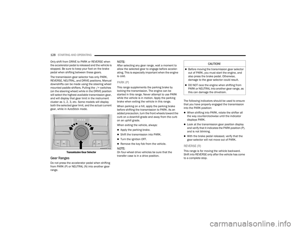
Transmission Gear Selector
Gear Ranges
Do not press the accelerator pedal when shifting
from PARK (P) or NEUTRAL (N) into another gear
range.
NOTE:After selecting any gear range, wait a moment to
allow the selected gear to engage before acceler -
ating. This is especially important when the engine
is cold.
PARK (P)
This range supplements the parking brake by
locking the transmission. The engine can be
started in this range. Never attempt to use PARK
while the vehicle is in motion. Apply the parking
brake when exiting the vehicle in this range.
When parking on a hill, apply the parking brake
before shifting the transmission to PARK. As an
added precaution, turn the front wheels toward the
curb on a downhill grade and away from the curb
on an uphill grade.
When exiting the vehicle, always:
Apply the parking brake.
Shift the transmission into PARK.
Turn the ignition OFF.
Remove the key fob from the vehicle.
NOTE:On four-wheel drive vehicles be sure that the
transfer case is in a drive position. The following indicators should be used to ensure
that you have properly engaged the transmission
into the PARK position:
When shifting into PARK, rotate the shifter all
the way counterclockwise until the indicator
displays PARK.
Look at the transmission gear position display
and verify that it indicates the PARK position (P),
and is not blinking.
With the brake pedal released, verify that the
gear selector will not move out of PARK.
REVERSE (R)
This range is for moving the vehicle backward.
Shift into REVERSE only after the vehicle has come
to a complete stop.
CAUTION!
Before moving the transmission gear selector
out of PARK, you must start the engine, and
also press the brake pedal. Otherwise,
damage to the gear selector could result.
DO NOT race the engine when shifting from
PARK or NEUTRAL into another gear range, as
this can damage the drivetrain.
23_WL_OM_EN_USC_t.book Page 128
Page 193 of 424
STARTING AND OPERATING191
TRAILER HITCH RECEIVER COVER
R
EMOVAL — IF EQUIPPED
Your vehicle may be equipped with a trailer hitch
receiver cover, this must be removed to access the
trailer hitch receiver. This cover is located at the
bottom center of the rear fascia/bumper.
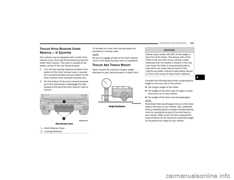
1. Turn the two locking retainers located at the
bottom of the hitch receiver cover a quarter
turn counterclockwise and pull bottom of the
hitch receiver cover outward (towards you).
2. Pull the bottom of the cover outward (towards you) then downwards to disengage the tabs
located at the top of the hitch receiver cover to
remove.
Hitch Receiver Cover
To reinstall the cover after towing repeat the
procedure in reverse order.NOTE:Be sure to engage all tabs of the hitch receiver
cover in the fascia/bumper prior to installation.
TRAILER AND TONGUE WEIGHT
Never exceed the maximum tongue weight
stamped on your fascia/bumper or trailer hitch.
Weight Distribution
Consider the following items when computing the
weight on the rear axle of the vehicle:
The tongue weight of the trailer.
The weight of any other type of cargo or equip
-
ment put in or on your vehicle.
The weight of the driver and all passengers.
NOTE:Remember that everything put into or on the trailer
adds to the load on your vehicle. Also, additional
factory-installed options or dealer-installed options
must be considered as part of the total load on
your vehicle. Refer to the Tire And Loading Infor -
mation Placard for the maximum combined weight
of occupants and cargo for your vehicle.
1 — Hitch Receiver Cover
2 — Locking Retainers
WARNING!
Always load a trailer with 60% of the weight in
the front of the trailer. This places 10% of the
GTW on the tow hitch of your vehicle. Loads
balanced over the wheels or heavier in the rear
can cause the trailer to sway severely side to
side which will cause loss of control of the
vehicle and trailer. Failure to load trailers heavier
in front is the cause of many trailer collisions.
4
23_WL_OM_EN_USC_t.book Page 191
Page 215 of 424

MULTIMEDIA213
Clock & Date
Rear Seat Alert
When this setting is turned on and the rear doors are opened while the engine is
running, or if the engine is turned on within 10 minutes of the door opening, a
message will appear to check the rear seat when the vehicle is powered OFF.
Setting Name
Description
When the Clock & Date button is pressed on the touchscreen, the system displays the different options related to the vehicle’s internal clock.
NOTE:Depending on the vehicle’s options, feature settings may vary.
Setting NameDescription
Sync Time With GPS This setting will sync the time to the GPS receiver in the system. The system
will control the time via the GPS location.
Time Format This setting will allow you to set the time format (AM/PM). Sync Time With GPS
must be off for this setting to be available. The “12 hrs” setting will set the
time to a 12-hour format. The “24 hrs” setting will set the time to a 24-hour
format.
Set Time This setting will allow you to set the hours and minutes. Sync Time With GPS
must be off for this setting to be available. The “+” setting will increase the
hours or minutes. The “-” setting will decrease the hours or minutes.
Set Date This setting will allow you to set the day, month and year. Using “+” or “-”, you
can scroll through the available days, months, and years.
Show Time and Date During Screen Off This setting will allow you to show the time and date while the screen is off.
Available options are “On” and “Off”.
5
23_WL_OM_EN_USC_t.book Page 213
Page 230 of 424
228MULTIMEDIA
STEERING WHEEL AUDIO CONTROLS
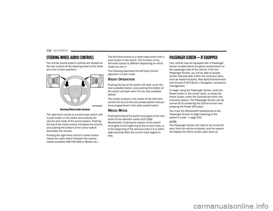
The remote sound system controls are located on
the rear surface of the steering wheel at the three
and nine o’clock positions.
Steering Wheel Audio Controls
The right-hand control is a rocker-type switch with
a push button in the center and controls the
volume and mode of the sound system. Pushing
the top of the rocker switch increases the volume,
and pushing the bottom of the rocker switch
decreases the volume.
Pushing the right-hand control’s center button
makes the radio switch between the various
modes available (AM/FM/SXM or Media, etc.) The left-hand control is a rocker-type switch with a
push button in the center. The function of the
left-hand control is different depending on which
mode you are in.
The following describes the left-hand control
operation in each mode.
RADIO OPERATION
Pushing the top of the switch will seek up for the
next available station, and pushing the bottom of
the switch will seek down for the next available
station.
The button located in the center of the left-hand
control will tune to the next preset station that you
have programmed in the radio preset button.
MEDIA MODE
Pushing the top of the switch once goes to the next
track on the selected media (AUX/USB/
Bluetooth®). Pushing the bottom of the switch
once goes to the beginning of the current track, or
to the beginning of the previous track if it is within
eight seconds after the current track begins to
play.
PASSENGER SCREEN — IF EQUIPPED
Your vehicle may be equipped with a Passenger
Screen located above the glove compartment on
the passenger side of the vehicle. From the
Passenger Screen, you will be able to access
similar features seen within the Uconnect radio,
such as media functions, Rear Seat Entertainment
with Amazon FireTV Built-in, Navigation, and device
management.
To begin using the Passenger Screen, push the
Power button in the center stack, or press the
Power button under the Controls tab within the
Uconnect system. The Passenger Screen can be
turned off by accessing the Control screen and
pressing the Power Off button.
You must link Bluetooth® headphones to the
Passenger Screen to begin listening to the
system’s audio Ú
page 232.
NOTE:The Passenger Screen will need to be turned On
each time the vehicle is started, and the system
will display the Home screen upon boot up.
23_WL_OM_EN_USC_t.book Page 228
Page 316 of 424
314IN CASE OF EMERGENCY
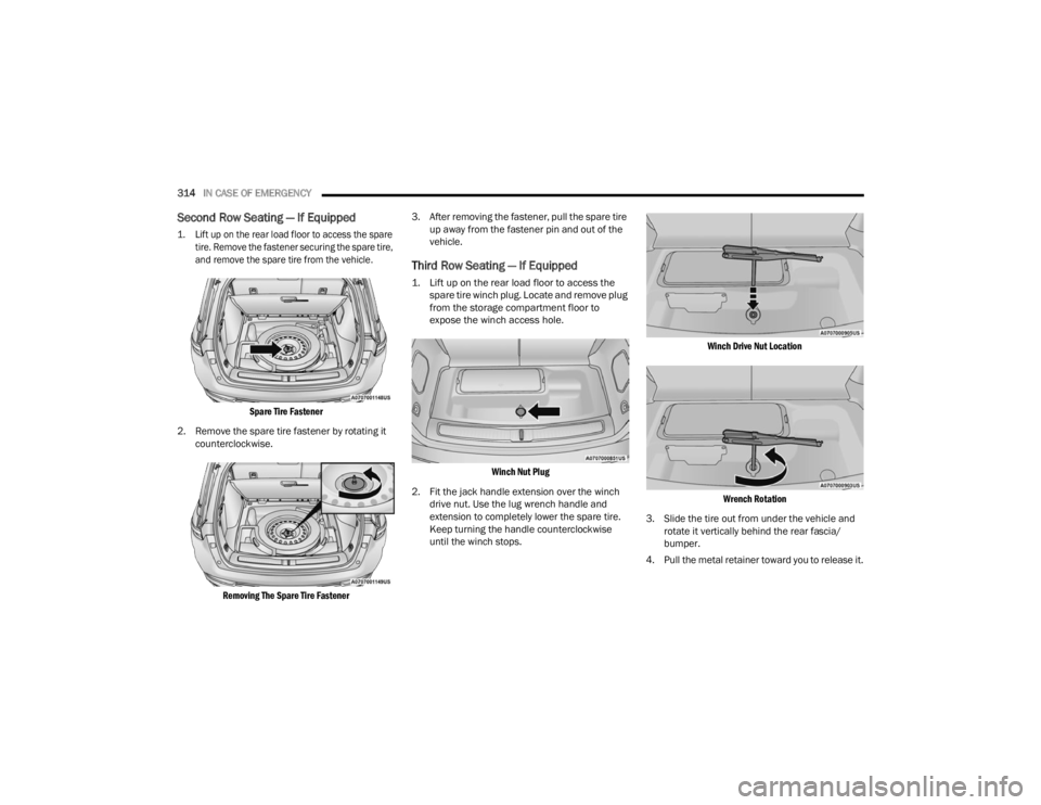
Second Row Seating — If Equipped
1. Lift up on the rear load floor to access the spare
tire. Remove the fastener securing the spare tire,
and remove the spare tire from the vehicle.
Spare Tire Fastener
2. Remove the spare tire fastener by rotating it counterclockwise.
Removing The Spare Tire Fastener
3. After removing the fastener, pull the spare tire
up away from the fastener pin and out of the
vehicle.
Third Row Seating — If Equipped
1. Lift up on the rear load floor to access the spare tire winch plug. Locate and remove plug
from the storage compartment floor to
expose the winch access hole.
Winch Nut Plug
2. Fit the jack handle extension over the winch drive nut. Use the lug wrench handle and
extension to completely lower the spare tire.
Keep turning the handle counterclockwise
until the winch stops.
Winch Drive Nut Location
Wrench Rotation
3. Slide the tire out from under the vehicle and rotate it vertically behind the rear fascia/
bumper.
4. Pull the metal retainer toward you to release it.
23_WL_OM_EN_USC_t.book Page 314
Page 318 of 424

316IN CASE OF EMERGENCY
1. Loosen (but do not remove) the wheel lug nuts, using the lug wrench by turning them
counterclockwise, one turn, while the wheel is
still on the ground.
Loosen Lug Nuts
2. Assemble the jack and jacking tools Úpage 311.
Jack And Tools Assembled
NOTE:Proper placement for the front and rear jacking
locations is critical. See the following images for
proper jacking locations.
Jacking Locations
3. For the front axle, place the jack on the body flange just behind the front tire as indicated by
the triangular lift point symbol on the sill
molding. Do not raise the vehicle until you are
sure the jack is fully engaged.
Front Lifting Point
NOTE:The jack must be placed straight on with handle
facing outwards.
Front Jacking Location
23_WL_OM_EN_USC_t.book Page 316
Page 319 of 424
IN CASE OF EMERGENCY317
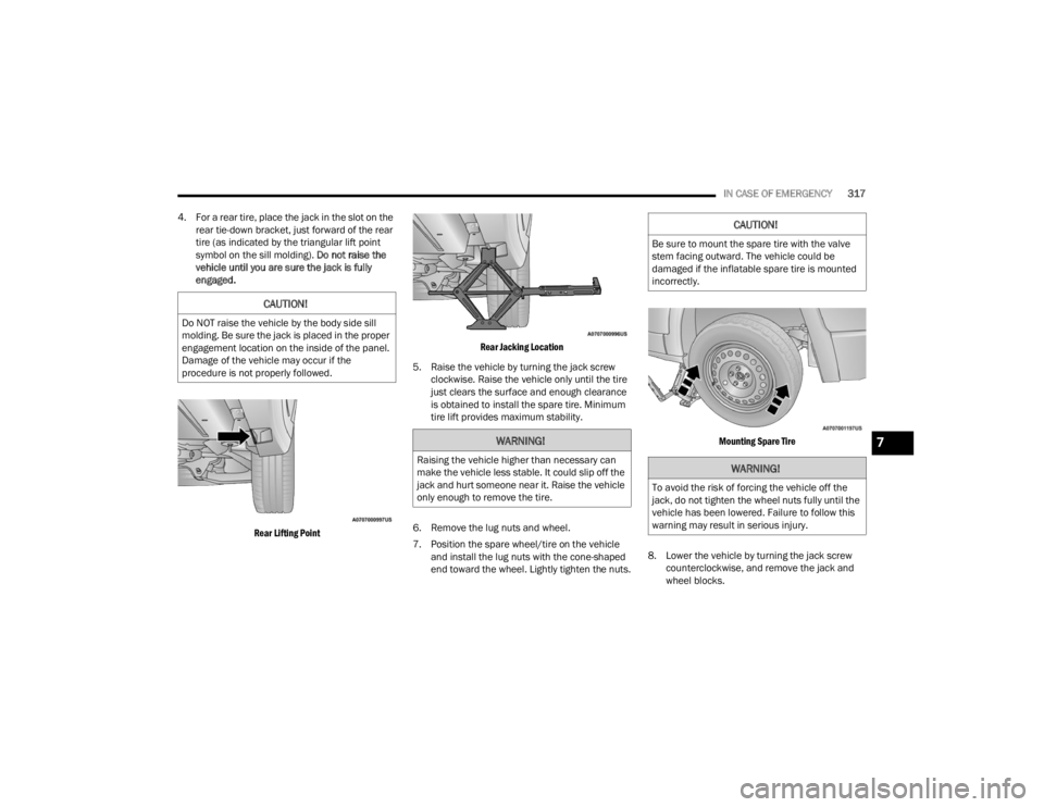
4. For a rear tire, place the jack in the slot on the rear tie-down bracket, just forward of the rear
tire (as indicated by the triangular lift point
symbol on the sill molding). Do not raise the
vehicle until you are sure the jack is fully
engaged.
Rear Lifting Point Rear Jacking Location
5. Raise the vehicle by turning the jack screw clockwise. Raise the vehicle only until the tire
just clears the surface and enough clearance
is obtained to install the spare tire. Minimum
tire lift provides maximum stability.
6. Remove the lug nuts and wheel.
7. Position the spare wheel/tire on the vehicle and install the lug nuts with the cone-shaped
end toward the wheel. Lightly tighten the nuts.
Mounting Spare Tire
8. Lower the vehicle by turning the jack screw counterclockwise, and remove the jack and
wheel blocks.
CAUTION!
Do NOT raise the vehicle by the body side sill
molding. Be sure the jack is placed in the proper
engagement location on the inside of the panel.
Damage of the vehicle may occur if the
procedure is not properly followed.
WARNING!
Raising the vehicle higher than necessary can
make the vehicle less stable. It could slip off the
jack and hurt someone near it. Raise the vehicle
only enough to remove the tire.
CAUTION!
Be sure to mount the spare tire with the valve
stem facing outward. The vehicle could be
damaged if the inflatable spare tire is mounted
incorrectly.
WARNING!
To avoid the risk of forcing the vehicle off the
jack, do not tighten the wheel nuts fully until the
vehicle has been lowered. Failure to follow this
warning may result in serious injury.
7
23_WL_OM_EN_USC_t.book Page 317
Page 320 of 424
318IN CASE OF EMERGENCY
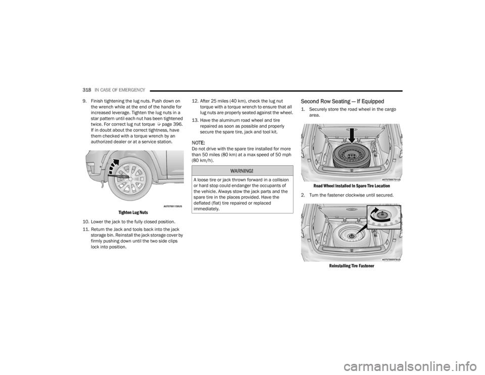
9. Finish tightening the lug nuts. Push down on the wrench while at the end of the handle for
increased leverage. Tighten the lug nuts in a
star pattern until each nut has been tightened
twice. For correct lug nut torque Úpage 396.
If in doubt about the correct tightness, have
them checked with a torque wrench by an
authorized dealer or at a service station.
Tighten Lug Nuts
10. Lower the jack to the fully closed position.
11. Return the Jack and tools back into the jack storage bin. Reinstall the jack storage cover by
firmly pushing down until the two side clips
lock into position. 12. After 25 miles (40 km), check the lug nut
torque with a torque wrench to ensure that all
lug nuts are properly seated against the wheel.
13. Have the aluminum road wheel and tire repaired as soon as possible and properly
secure the spare tire, jack and tool kit.
NOTE:Do not drive with the spare tire installed for more
than 50 miles (80 km) at a max speed of 50 mph
(80 km/h).
Second Row Seating — If Equipped
1. Securely store the road wheel in the cargo area.
Road Wheel Installed In Spare Tire Location
2. Turn the fastener clockwise until secured.
Reinstalling Tire Fastener
WARNING!
A loose tire or jack thrown forward in a collision
or hard stop could endanger the occupants of
the vehicle. Always stow the jack parts and the
spare tire in the places provided. Have the
deflated (flat) tire repaired or replaced
immediately.
23_WL_OM_EN_USC_t.book Page 318