wheel JEEP GRAND CHEROKEE 2023 Manual PDF
[x] Cancel search | Manufacturer: JEEP, Model Year: 2023, Model line: GRAND CHEROKEE, Model: JEEP GRAND CHEROKEE 2023Pages: 424, PDF Size: 15.48 MB
Page 249 of 424
MULTIMEDIA247
The selectable modes are as follows:
Rock — Vehicle Must Be In 4WD Low
Sand/Mud
Snow
Auto — Default
Sport
NOTE:The Off-Road Pages Status Bar will also display the
current Selec-Terrain Mode.
SUSPENSION — IF EQUIPPED
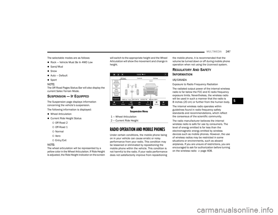
The Suspension page displays information
concerning the vehicle’s suspension.
The following information is displayed:
Wheel Articulation
Current Ride Height Status
Off-Road 2
Off-Road 1
Normal
Aero
Entry/Exit
NOTE:The wheel articulation will be represented by a
yellow color in the Wheel Articulation. If Ride Height
is adjusted, the Ride Height indicator on the screen will switch to the appropriate height and the Wheel
Articulation will show the movement and change in
height.
Suspension Menu
RADIO OPERATION AND MOBILE PHONES
Under certain conditions, the mobile phone being
on in your vehicle can cause erratic or noisy
performance from your radio. This condition may
be lessened or eliminated by repositioning the
mobile phone within the vehicle. This condition is
not harmful to the radio. If your radio performance
does not satisfactorily improve from repositioning the mobile phone, it is recommended that the
volume be turned down or off during mobile phone
operation when not using the Uconnect system.
REGULATORY AND SAFETY
I
NFORMATION
US/CANADA
Exposure to Radio Frequency Radiation
The radiated output power of the internal wireless
radio is far below the FCC and IC radio frequency
exposure limits. Nevertheless, the wireless radio
will be used in such a manner that the radio is
8 inches (20 cm) or further from the human body.
The internal wireless radio operates within
guidelines found in radio frequency safety
standards and recommendations, which reflect
the consensus of the scientific community.
The radio manufacturer believes the internal
wireless radio is safe for use by consumers. The
level of energy emitted is far less than the
electromagnetic energy emitted by wireless
devices such as mobile phones. However, the use
of wireless radios may be restricted in some
situations or environments, such as aboard
airplanes. If you are unsure of restrictions, you are
encouraged to ask for authorization before turning
on the wireless radio Ú page 408.
1 — Wheel Articulation
2 — Current Ride Height
5
23_WL_OM_EN_USC_t.book Page 247
Page 250 of 424
248 (Continued)
SAFETY
SAFETY FEATURES
ANTI-LOCK BRAKE SYSTEM (ABS)
The ABS provides increased vehicle stability and
brake performance under most braking conditions.
The system automatically prevents wheel lock and
enhances vehicle control during braking.
The ABS performs a self-check cycle to ensure that
the ABS is working properly each time the vehicle
is started and driven. During this self-check, you
may hear a slight clicking sound as well as some
related motor noises.
The ABS is activated during braking when the
system detects one or more wheels are beginning
to lock. Road conditions such as ice, snow, gravel,
bumps, railroad tracks, loose debris, or panic stops
may increase the likelihood of ABS activation(s).
You also may experience the following normal
characteristics when the ABS activates:
ABS motor noise or clicking sounds (you may
continue to hear for a short time after the stop)
Brake pedal pulsations
A slight drop of the brake pedal at the end of the
stopThe ABS is designed to function with the Original
Equipment Manufacturer (OEM) tires. Modification
may result in degraded ABS performance.
Anti-Lock Brake System (ABS) Warning
Light
The yellow ABS Warning Light will turn on when the
ignition is placed in the ON/RUN mode and may
stay on for as long as four seconds.
If the ABS Warning Light remains on or comes on
while driving, it indicates that the anti-lock portion
of the brake system is not functioning and that
service is required. However, the conventional
brake system will continue to operate normally if
the ABS Warning Light is on.
WARNING!
The ABS contains sophisticated electronic
equipment that may be susceptible to interfer
-
ence caused by improperly installed or high
output radio transmitting equipment. This
interference can cause possible loss of
anti-lock braking capability. Installation of
such equipment should be performed by qual -
ified professionals.
Pumping of the Anti-Lock Brakes will diminish
their effectiveness and may lead to a collision.
Pumping makes the stopping distance longer.
Just press firmly on your brake pedal when you
need to slow down or stop.
The ABS cannot prevent the natural laws of
physics from acting on the vehicle, nor can it
increase braking or steering efficiency beyond
that afforded by the condition of the vehicle
brakes and tires or the traction afforded.
The ABS cannot prevent collisions, including
those resulting from excessive speed in turns,
following another vehicle too closely, or hydro -
planing.
The capabilities of an ABS equipped vehicle
must never be exploited in a reckless or
dangerous manner that could jeopardize the
user’s safety or the safety of others.
WARNING!
23_WL_OM_EN_USC_t.book Page 248
Page 251 of 424
SAFETY249
If the ABS Warning Light is on, the brake system
should be serviced as soon as possible to restore
the benefits of Anti-Lock Brakes. If the ABS
Warning Light does not come on when the ignition
is placed in the ON/RUN mode, have the light
repaired as soon as possible.
DROWSY DRIVER DETECTION (DDD) —
I
F EQUIPPED
DDD detects when the driver is feeling fatigued
and warns the driver to pull over and take a break.
To Activate/Deactivate
DDD can be activated and deactivated through the
Uconnect system by selecting the following in order:
1. “Safety & Driving Assistance”
2. “Drowsy Driver Detection”
System Operation
Using feedback obtained from the driver’s steering
patterns, any buttons/switches that are pressed,
and from the front camera, the system implements
two operating logics:
The first operating logic takes the driving style
into account, observing the road and detecting
to what extent the driver can continue driving
with few lane crossing events.
The second operating logic measures the time
spent behind the wheel with the vehicle speed
above 40 mph (60 km/h) and below 100 mph
(160 km/h).
If the driving style indicates that the driver is
unable to follow the road trajectory and respect the
horizontal lane markings while within the operating
speed range of the system, a pop up will display on
the instrument cluster display to suggest that the
driver should stop for a break. An audible signal
will also sound.
If the driver accepts the suggestion provided by the
system by pushing the “OK” button on the left side
of the steering wheel, the message will disappear
from the display.
If the driver does not acknowledge the warning, it
will be displayed for 60 seconds and then
disappear.
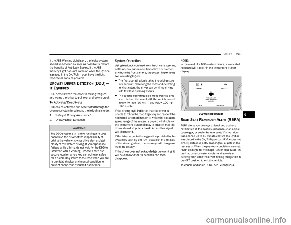
NOTE:In the event of a DDD system failure, a dedicated
message will appear in the instrument cluster
display.
DDD Warning Message
REAR SEAT REMINDER ALERT (RSRA)
RSRA alerts you through a visual and auditory
notification of the possible presence of an object,
passenger, or pet in the rear seats if a rear door
was opened up to 10 minutes before the ignition
was placed in the ON/RUN position. RSRA does not
directly detect objects, passengers, or pets in the
rear seats. When the previous conditions are met,
RSRA displays the message “Check Rear Seat” on
the instrument cluster display and sounds an
auditory alert upon the driver placing the ignition in
the OFF position to exit the vehicle.
To enable or disable RSRA, see Ú page 204.WARNING!
The DDD system is an aid for driving and does
not relieve the driver of the responsibility of
driving the vehicle. Always drive alert and get
plenty of rest before driving. If you experience
fatigue while driving, do not wait for the DDD to
intervene with a warning. Choose a safe and
secure location where you can pull over safely
for a break. Only return to the road when you are
in the right physical and mental condition to
prevent endangering yourself and others.
6
23_WL_OM_EN_USC_t.book Page 249
Page 253 of 424

SAFETY251
Electronic Brake Force Distribution (EBD)
EBD manages the distribution of the braking
torque between the front and rear axles by limiting
braking pressure to the rear axle. This is done to
prevent overslip of the rear wheels to avoid vehicle
instability, and to prevent the rear axle from
entering ABS before the front axle.
Electronic Roll Mitigation (ERM)
ERM anticipates the potential for wheel lift by
monitoring the driver’s steering wheel input and
the speed of the vehicle. When ERM determines
that the rate of change of the steering wheel angle
and vehicle’s speed are sufficient to potentially
cause wheel lift, it then applies the appropriate
brake and may also reduce engine power to lessen
the chance that wheel lift will occur. ERM can only
reduce the chance of wheel lift occurring during
severe or evasive driving maneuvers; it cannot
prevent wheel lift due to other factors, such as
road conditions, leaving the roadway, or striking
objects or other vehicles.
NOTE:ERM is disabled any time the ESC is in “Full Off”
mode (if equipped). See Ú page 251 for a
complete explanation of the available ESC modes.
Electronic Stability Control (ESC)
ESC enhances directional control and stability of
the vehicle under various driving conditions. ESC
corrects for oversteering or understeering of the
vehicle by applying the brake of the appropriate
wheel(s) to assist in counteracting the following
conditions. Engine power may also be reduced to
help the vehicle maintain the desired path.
Oversteer — when the vehicle is turning more
than appropriate for the steering wheel position.
Understeer — when the vehicle is turning less
than appropriate for the steering wheel position.
ESC uses sensors in the vehicle to determine the
vehicle path intended by the driver and compares
it to the actual path of the vehicle. When the actual
path does not match the intended path, ESC
applies the brake of the appropriate wheel to
assist in counteracting the oversteer or understeer
condition.
The ESC Activation/Malfunction Indicator Light
located in the instrument cluster will start to flash
as soon as the ESC system becomes active. The
ESC Activation/Malfunction Indicator Light also
flashes when the Traction Control System (TCS) is
active. If the ESC Activation/Malfunction Indicator
Light begins to flash during acceleration, ease up
on the accelerator and apply as little throttle as
possible. Be sure to adapt your speed and driving
to the prevailing road conditions.
WARNING!
Many factors, such as vehicle loading, road
conditions and driving conditions, influence the
chance that wheel lift or rollover may occur. ERM
cannot prevent all wheel lift or rollovers,
especially those that involve leaving the roadway
or striking objects or other vehicles. The
capabilities of an ERM-equipped vehicle must
never be exploited in a reckless or dangerous
manner which could jeopardize the user's safety
or the safety of others.
6
23_WL_OM_EN_USC_t.book Page 251
Page 254 of 424

252SAFETY
ESC Operating Modes
Depending upon model and mode of operation, the
ESC system may have multiple operating modes.
ESC On
This is the normal operating mode for the ESC.
Whenever the vehicle is started, the ESC system
will be in this mode. This mode should be used for
most driving conditions. Alternate ESC modes
should only be used for specific reasons as noted
in the following paragraphs.
Partial Off
This mode may be useful if the vehicle becomes
stuck. This mode may modify TCS and ESC
thresholds for activation, which allows for more
wheel spin than normally allowed.
To enter the “Partial Off” mode, momentarily push
the ESC OFF button and the ESC OFF Indicator
Light will illuminate. To turn the ESC on again,
momentarily push the ESC OFF button and the ESC
OFF Indicator Light will turn off.
NOTE:For vehicles with multiple partial ESC modes, the
push and release of the button will toggle the ESC
modes. Multiple attempts may be required to
return to "ESC On" mode.
ESC Activation/Malfunction Indicator Light
And ESC OFF Indicator Light
The ESC Activation/Malfunction Indicator
Light in the instrument cluster will come
on when the ignition is placed in the ON/
RUN mode. It should go out with the
engine running. If the ESC Activation/Malfunction
Indicator Light comes on continuously with the
engine running, a malfunction has been detected
in the ESC system. If this light remains on after
several ignition cycles, and the vehicle has been
driven several miles (kilometers) at speeds greater
than 30 mph (48 km/h), see an authorized dealer
as soon as possible to have the problem
diagnosed and corrected.
WARNING!
Electronic Stability Control (ESC) cannot prevent
the natural laws of physics from acting on the
vehicle, nor can it increase the traction afforded by
prevailing road conditions. ESC cannot prevent
accidents, including those resulting from exces -
sive speed in turns, driving on very slippery
surfaces, or hydroplaning. ESC also cannot
prevent accidents resulting from loss of vehicle
control due to inappropriate driver input for the
conditions. Only a safe, attentive, and skillful
driver can prevent accidents. The capabilities of
an ESC equipped vehicle must never be exploited
in a reckless or dangerous manner which could
jeopardize the user’s safety or the safety of others.
Vehicle modifications, or failure to properly
maintain your vehicle, may change the
handling characteristics of your vehicle, and
may negatively affect the performance of the
ESC system. Changes to the steering system,
suspension, braking system, tire type and size
or wheel size may adversely affect ESC perfor -
mance. Improperly inflated and unevenly worn
tires may also degrade ESC performance. Any
vehicle modification or poor vehicle mainte -
nance that reduces the effectiveness of the
ESC system can increase the risk of loss of
vehicle control, vehicle rollover, personal
injury and death.
WARNING!
When in “Partial Off” mode, the TCS function -
ality of ESC (except for the limited slip feature
described in the TCS section) has been
disabled and the ESC OFF Indicator Light will
be illuminated. When in “Partial Off” mode,
the engine power reduction feature of TCS is
disabled, and the enhanced vehicle stability
offered by the ESC system is reduced.
Trailer Sway Control (TSC) is disabled when
the ESC system is in the “Partial Off” mode.
23_WL_OM_EN_USC_t.book Page 252
Page 259 of 424

SAFETY257
Feedback To The Driver:
The instrument cluster has an SSC icon and the
SSC switch has an LED which offer feedback to the
driver about the state SSC is in.
The cluster icon and switch light will illuminate
and remain on solid when SSC is enabled or
activated. This is the normal operating condition
for SSC.
The cluster icon and switch light will flash for
several seconds then extinguish when the driver
pushes the SSC switch but enable conditions
are not met.
The cluster icon and switch light will flash for
several seconds then extinguish when SSC
disables due to excess speed.
The cluster icon and switch light will flash then
extinguish when SSC deactivates due to over -
heated brakes.
Traction Control System (TCS)
The TCS monitors the amount of wheel spin of
each of the driven wheels. If wheel spin is
detected, the TCS may apply brake pressure to the
spinning wheel(s) and/or reduce engine power to
provide enhanced acceleration and stability. A
feature of the TCS, Brake Limited Differential (BLD)
functions similarly to a limited slip differential and
controls the wheel spin across a driven axle. If one
wheel on a driven axle is spinning faster than the
other, the system will apply the brake of the
spinning wheel. This will allow more engine power
to be applied to the wheel that is not spinning. BLD
may remain enabled even if TCS and Electronic
Stability Control (ESC) are in reduced modes.
Trailer Sway Control (TSC)
TSC uses sensors in the vehicle to recognize an
excessively swaying trailer and will take the
appropriate actions to attempt to stop the sway.
TSC will become active automatically once an
excessively swaying trailer is recognized.
NOTE:TSC cannot stop all trailers from swaying. Always
use caution when towing a trailer and follow the
trailer tongue weight recommendations
Ú page 185.
When TSC is functioning, the ESC Activation/
Malfunction Indicator Light will flash, the engine
power may be reduced and you may feel the
brakes being applied to individual wheels to
attempt to stop the trailer from swaying. TSC is
disabled when the ESC system is in the “Partial
Off” mode.
WARNING!
SSC is only intended to assist the driver in
controlling vehicle speed when driving in off
road conditions. The driver must remain
attentive to the driving conditions and is
responsible for maintaining a safe vehicle
speed.
WARNING!
If TSC activates while driving, slow the vehicle
down, stop at the nearest safe location, and
adjust the trailer load to eliminate trailer sway.6
23_WL_OM_EN_USC_t.book Page 257
Page 267 of 424

SAFETY265
NOTE:When filling warm tires, the tire pressure may need
to be increased up to an additional 4 psi (28 kPa)
above the recommended cold placard pressure in
order to turn the TPMS Warning Light off.
The system will automatically update and the
TPMS Warning Light will extinguish once the
updated tire pressures have been received. The
vehicle may need to be driven for up to 20 minutes
above 15 mph (24 km/h) to receive this
information.
For example, your vehicle has a recommended
cold (parked for more than three hours) tire
pressure of 36 psi (248 kPa). If the ambient
temperature is 68°F (20°C) and the measured tire
pressure is 28 psi (193 kPa), a temperature drop
to 20°F (-7°C) will decrease the tire pressure to
approximately 24 psi (165 kPa). This tire pressure
is sufficiently low enough to turn on the TPMS
Warning Light. Driving the vehicle may cause the
tire pressure to rise to approximately 28 psi
(193 kPa), but the TPMS Warning Light will still be
on. In this situation, the TPMS Warning Light will
turn off only after the tires have been inflated to
the vehicle’s recommended cold tire pressure
value.NOTE:
The TPMS is not intended to replace normal tire
care and maintenance, or to provide warning of
a tire failure or condition.
The TPMS should not be used as a tire pressure
gauge while adjusting your tire pressure, unless
equipped with Tire Fill Alert.
Driving on a significantly underinflated tire
causes the tire to overheat and can lead to tire
failure. Underinflation also reduces fuel effi -
ciency and tire tread life, and may affect the
vehicle’s handling and stopping ability.
The TPMS is not a substitute for proper tire
maintenance, and it is the driver’s responsibility
to maintain correct tire pressure using an accu -
rate tire gauge, even if underinflation has not
reached the level to trigger illumination of the
TPMS Warning Light.
Seasonal temperature changes will affect tire
pressure, and the TPMS will monitor the actual
tire pressure in the tire.
CAUTION!
The TPMS has been optimized for the original
equipment tires and wheels. TPMS pressures
and warnings have been established for the tire
size equipped on your vehicle. Undesirable
system operation or sensor damage may result
when using replacement equipment that is not
of the same size, type, and/or style. The TPMS
sensor is not designed for use on aftermarket
wheels and may contribute to a poor overall
system performance or sensor damage.
Customers are encouraged to use Original
Equipment Manufacturer (OEM) wheels to
ensure proper TPMS feature operation.
Using aftermarket tire sealants may cause the
Tire Pressure Monitoring System (TPMS)
sensor to become inoperable. After using an
aftermarket tire sealant it is recommended
that you take your vehicle to an authorized
dealership to have your sensor function
checked.
After inspecting or adjusting the tire pressure,
always reinstall the valve stem cap. This will
prevent moisture and dirt from entering the
valve stem, which could damage the Tire Pres -
sure Monitoring System sensor.
6
23_WL_OM_EN_USC_t.book Page 265
Page 268 of 424
266SAFETY
The Tire Pressure Monitoring System (TPMS) uses
wireless technology with wheel rim-mounted
electronic sensors to monitor tire pressure levels.
Sensors, mounted to each wheel as part of the
valve stem, transmit tire pressure readings to the
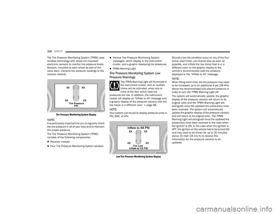
receiver module.
Tire Pressure Monitoring System Display
NOTE:It is particularly important for you to regularly check
the tire pressure in all of your tires and to maintain
the proper pressure.
The Tire Pressure Monitoring System (TPMS)
consists of the following components:
Receiver module
Four Tire Pressure Monitoring System sensors
Various Tire Pressure Monitoring System
messages, which display in the instrument
cluster, and a graphic displaying tire pressures
TPMS Warning Light
Tire Pressure Monitoring System Low
Pressure Warnings
The TPMS Warning Light will illuminate in
the instrument cluster, and an audible
chime will be activated, when one or
more of the four active road tire
pressures are low. In addition, the instrument
cluster will display an "Inflate to XX" message and
a graphic display of the pressure value(s) with the
low tire(s) in a different color Ú page 98.
NOTE:Your system can be set to display pressure units in
PSI, BAR, or kPa.
Low Tire Pressure Monitoring System Display
Should a low tire condition occur on any of the four
active road tire(s), you should stop as soon as
possible, and inflate the low tire(s) that is in a
different color on the graphic display to the
vehicle’s recommended cold tire pressure
displayed in the “Inflate to XX” message.
NOTE:When filling warm tires, the tire pressure may need
to be increased up to an additional 4 psi (28 kPa)
above the recommended cold placard pressure in
order to turn the TPMS Warning Light off.
The system will automatically update, the graphic
display of the pressure value(s) will return to its
original color and the TPMS Warning Light will
extinguish once the updated tire pressure(s) have
been received. The system will automatically
update the graphic display of the pressure value(s)
and will return to its original color. The TPMS
Warning Light will extinguish once the updated tire
pressure(s) have been received in the case when
the ignition is ON. In the case when the ignition is
OFF, the ignition on the vehicle has to be turned ON
and may need to be driven for up to 20 minutes
above 15 mph (24 km/h) to receive this
information for the pressure value(s) to be
updated.
23_WL_OM_EN_USC_t.book Page 266
Page 269 of 424

SAFETY267
Service TPMS Warning
The Tire Pressure Monitoring System Warning Light
will flash on and off for 75 seconds, and remain on
solid when a system fault is detected. The system
fault will also sound a chime. The instrument
cluster display will display a “SERVICE TPM
SYSTEM” message for a minimum of five seconds.
This message is then followed by a graphic display,
with “--“ in place of the pressure value(s),
indicating which Tire Pressure Monitoring System
sensor(s) is not being received.
If the ignition switch is cycled, this sequence will
repeat, providing the system fault still exists. If the
system fault no longer exists, the Tire Pressure
Monitoring System Warning Light will no longer
flash, the "SERVICE TPM SYSTEM" message will
not be present, and a pressure value will be
displayed instead of dashes. A system fault can
occur by any of the following:
Jamming due to electronic devices or driving
next to facilities emitting the same radio
frequencies as the TPMS sensors.
Lots of snow or ice around the wheels or wheel
housings.
Using tire chains on the vehicle.
Using wheels/tires not equipped with TPMS
sensors.
NOTE:A TPMS sensor is not offered on any size spare tire.
In either option of having a full size spare equipped
or not, the tire pressure is not monitored or
displayed on the cluster for the corresponding
spare tire location. If you install the spare tire in
place of a road tire that has a pressure below the
low-pressure warning limit, upon the next ignition
switch cycle, the Tire Pressure Monitoring System
Warning Light will remain on, a chime will sound,
and the instrument cluster display will still display
a pressure value in the different color graphic
display and an “Inflate to XX” message will be
displayed. After driving the vehicle for up to
20 minutes above 15 mph (24 km/h), the Tire
Pressure Monitoring System Warning Light will
flash on and off for 75 seconds and then remain on
solid. In addition, the instrument cluster display
will display a “SERVICE TPM SYSTEM" message for
five seconds and then display dashes (--) in place
of the pressure value. For each subsequent
ignition switch cycle, a chime will sound, the Tire
Pressure Monitoring System Warning Light will
flash on and off for 75 seconds and then remain on
solid, and the instrument cluster display will
display a "SERVICE TPM SYSTEM" message for five
seconds and then display dashes (--) in place of the
pressure value. Once you repair or replace the
original road tire, and reinstall it on the vehicle in
place of the spare tire, the TPMS will update auto -
matically. In addition, the Tire Pressure Monitoring System
Warning Light will turn off and the graphic in the
instrument cluster display will display a new
pressure value instead of dashes (--), as long as no
tire pressure is below the low-pressure warning
limit in any of the four active road tires. The vehicle
may need to be driven for up to 20 minutes above
15 mph (24 km/h) in order for the TPMS to receive
this information.
TPMS Deactivation — If Equipped
The Tire Pressure Monitoring System (TPMS) can
be deactivated by replacing all four wheel and tire
assemblies (road tires) with wheel and tire
assemblies that do not have TPMS sensors, such
as when installing winter wheel and tire
assemblies on your vehicle.
To deactivate the TPMS, first, replace all four wheel
and tire assemblies (road tires) with tires not
equipped with Tire Pressure Monitoring System
sensors. Then, drive the vehicle for 20 minutes
above 15 mph (24 km/h). The TPMS will chime,
the TPMS Warning Light will flash on and off for 75
seconds and then remain on. The instrument
cluster will display the “SERVICE TPM SYSTEM”
message and then display dashes (--) in place of
the pressure values.
6
23_WL_OM_EN_USC_t.book Page 267
Page 270 of 424

268SAFETY
Beginning with the next ignition cycle, the TPMS
will no longer chime or display the “SERVICE TPM
SYSTEM” message in the instrument cluster but
dashes (--) will remain in place of the pressure
values.
To reactivate the TPMS, replace all four wheel and
tire assemblies (road tires) with tires equipped with
TPMS sensors. Then, drive the vehicle for up to
20 minutes above 15 mph (24 km/h). The TPMS
will chime, the TPMS Warning Light will flash on
and off for 75 seconds and then turn off. The
instrument cluster will display the “SERVICE TPM
SYSTEM” message and then display pressure
values in place of the dashes. On the next ignition
cycle the "SERVICE TPM SYSTEM" message will no
longer be displayed as long as no system fault
exists.
Tire Fill Alert
This feature notifies the user when the placard tire
pressure is attained while inflating or deflating the
tire.
The customer may choose to disable or enable the
Tire Fill Alert feature in the apps menu of the
Uconnect system.
NOTE:
The Tire Fill Alert system will only support
inflating or deflating one tire at a time. The user
is required to wait until the hazard lights STOP flashing or 26-30 seconds after the desired
pressure is achieved in one wheel before
switching to another.
The Tire Fill Alert feature cannot be entered if an
existing TPMS fault is set to “active” or if the
system is in deactivation mode (if equipped).
The system will be activated when the system
detects an increase in tire pressure while filling the
tire. The ignition must be in the ON/RUN mode with
the transmission in PARK for vehicles equipped
with an automatic transmission. For vehicles
equipped with a manual transmission, the parking
brake must be applied.
NOTE:It is not required to have the engine running to
enter Tire Fill Alert mode.
The hazard lamps will come on to confirm the
vehicle is in Tire Fill Alert mode. If the hazard lamps
do not come on while inflating the tire, the Tire
Pressure Monitoring System sensor may be in an
inoperative position, preventing the TPMS sensor
signal from being received. In this case, the vehicle
may need to be moved slightly forward or
backward.
When Tire Fill Alert mode is entered, the tire
pressure display screen will be displayed in the
instrument cluster. Operation:
The horn will chirp once to let the user know
when to stop filling the tire, when it reaches
recommended pressure.
The horn will chirp three times if the tire is over
-
filled and will continue to chirp every five
seconds if the user continues to inflate the tire.
The horn will chirp once again when enough air
is let out to reach proper inflation level.
The horn will also chirp three times if the tire is
then underinflated and will continue to chirp
every five seconds if the user continues to
deflate the tire.
Selectable Tire Fill Alert (STFA) —
If Equipped
The Selectable Tire Fill Alert (STFA) system is an
optional feature that is included as part of the
normal Tire Fill Alert system. The system is
designed to allow you to select a pressure to inflate
or deflate the vehicle's front and rear axle tires to,
and to provide feedback while inflating or deflating
the vehicle's tires.
23_WL_OM_EN_USC_t.book Page 268