brake light JEEP GRAND CHEROKEE 2023 Owners Manual
[x] Cancel search | Manufacturer: JEEP, Model Year: 2023, Model line: GRAND CHEROKEE, Model: JEEP GRAND CHEROKEE 2023Pages: 424, PDF Size: 15.48 MB
Page 6 of 424
4
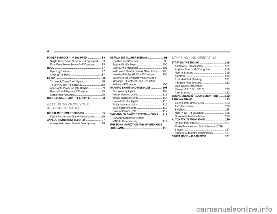
POWER SUNROOF — IF EQUIPPED .................... 83 Single Pane Power Sunroof — If Equipped ....83
Dual Pane Power Sunroof —If Equipped ........85
HOOD ...................................................................... 87
Opening The Hood............................................87
Closing The Hood .............................................87
LIFTGATE ................................................................. 88
To Unlock/Open The Liftgate...........................88
To Lock/Close The Liftgate ..............................88
Adjustable Power Liftgate Height ....................89
Hands-Free Liftgate — If Equipped .................89
Cargo Area Features ........................................90
ROOF LUGGAGE RACK — IF EQUIPPED ............. 93
GETTING TO KNOW YOUR
INSTRUMENT PANEL
DIGITAL INSTRUMENT CLUSTER ......................... 95
Digital Instrument Cluster Descriptions ..........96
ANALOG INSTRUMENT CLUSTER ........................ 97
Analog Instrument Cluster Descriptions .........98 INSTRUMENT CLUSTER DISPLAY.........................98
Location And Controls ......................................98
Engine Oil Life Reset .................................... 100
Display And Messages .................................. 101
Instrument Cluster Display Menu Items ..... 103
Head Up Display (HUD) — If Equipped ......... 105Battery Saver On/Battery Saver Mode
Message — Electrical Load Reduction
Actions — If Equipped ................................... 106
WARNING LIGHTS AND MESSAGES ................ 108
Red Warning Lights ....................................... 108
Yellow Warning Lights ................................... 111Yellow Indicator Lights .................................. 114
Green Indicator Lights .................................. 115
White Indicator Lights ................................... 116Blue Indicator Lights ..................................... 117
Gray Indicator Lights ..................................... 117
ONBOARD DIAGNOSTIC SYSTEM — OBD II ..... 117
Onboard Diagnostic System
(OBD II) Cybersecurity ................................... 117
EMISSIONS INSPECTION AND MAINTENANCE
PROGRAMS ......................................................... 118
STARTING AND OPERATING
STARTING THE ENGINE ...................................... 119
Automatic Transmission ............................... 119
Keyless Enter ‘n Go™ — Ignition .................. 119
Normal Starting ............................................ 119
AutoPark ........................................................ 120
Extended Park Starting ................................. 121
If Engine Fails To Start .................................. 122Cold Weather Operation
(Below –22°F Or −30°C) ............................ 122
After Starting ................................................. 122
ENGINE BREAK-IN RECOMMENDATIONS ......... 122
PARKING BRAKE ................................................. 123
Electric Park Brake (EPB) ............................. 123Auto Park Brake ............................................ 125
SafeHold ........................................................ 125
Hold ‘N Go — If Equipped ............................. 125Brake Maintenance Mode ............................ 125
AUTOMATIC TRANSMISSION ............................. 126
Ignition Park Interlock................................... 127
Brake/Transmission Shift Interlock (BTSI)
System .......................................................... 1278-Speed Automatic Transmission ............... 127
SPORT MODE — IF EQUIPPED............................ 131
23_WL_OM_EN_USC_t.book Page 4
Page 14 of 424
12
VEHICLE MODIFICATIONS/ALTERATIONS
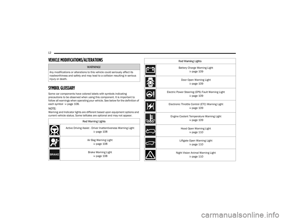
SYMBOL GLOSSARY
Some car components have colored labels with symbols indicating
precautions to be observed when using this component. It is important to
follow all warnings when operating your vehicle. See below for the definition of
each symbol Úpage 108.
NOTE:Warning and Indicator lights are different based upon equipment options and
current vehicle status. Some telltales are optional and may not appear.
WARNING!
Any modifications or alterations to this vehicle could seriously affect its
roadworthiness and safety and may lead to a collision resulting in serious
injury or death.
Red Warning Lights
Active Driving Assist - Driver Inattentiveness Warning Light Úpage 108
Air Bag Warning Light Úpage 108
Brake Warning Light Úpage 108
Battery Charge Warning Light
Úpage 109
Door Open Warning Light Úpage 109
Electric Power Steering (EPS) Fault Warning Light Úpage 109
Electronic Throttle Control (ETC) Warning Light Úpage 109
Engine Coolant Temperature Warning Light Úpage 109
Hood Open Warning Light Úpage 110
Liftgate Open Warning Light Úpage 110
Night Vision Animal Warning Light Úpage 110
Red Warning Lights
23_WL_OM_EN_USC_t.book Page 12
Page 15 of 424
13
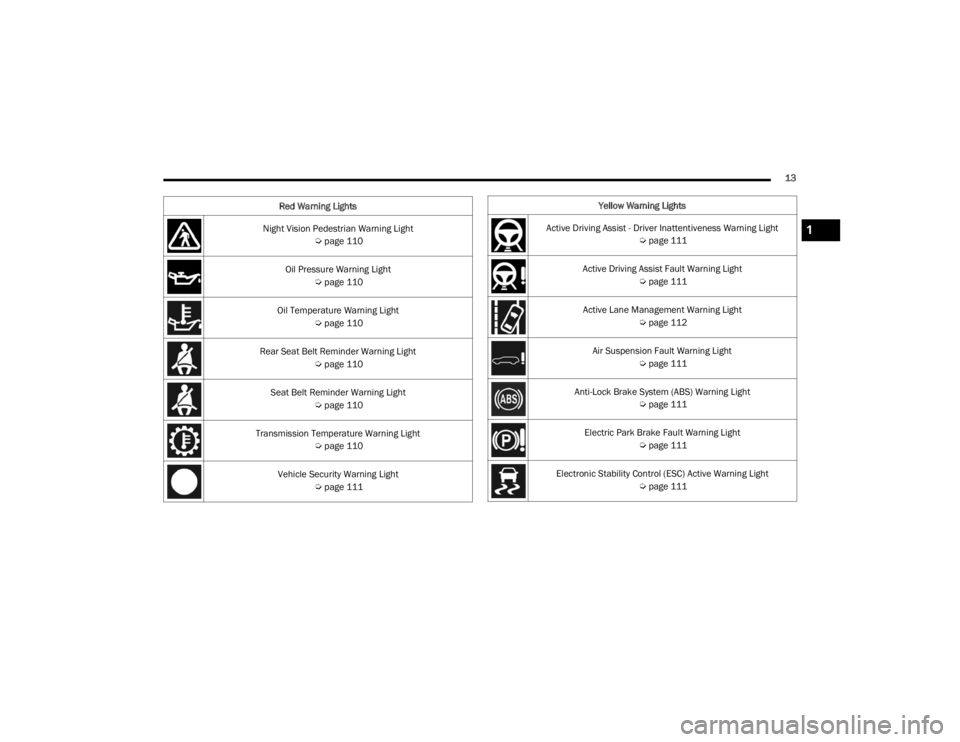
Night Vision Pedestrian Warning Light Úpage 110
Oil Pressure Warning Light Úpage 110
Oil Temperature Warning Light Úpage 110
Rear Seat Belt Reminder Warning Light Úpage 110
Seat Belt Reminder Warning Light Úpage 110
Transmission Temperature Warning Light Úpage 110
Vehicle Security Warning Light Úpage 111
Red Warning Lights
Yellow Warning Lights
Active Driving Assist - Driver Inattentiveness Warning Light Úpage 111
Active Driving Assist Fault Warning Light Úpage 111
Active Lane Management Warning Light Úpage 112
Air Suspension Fault Warning Light Úpage 111
Anti-Lock Brake System (ABS) Warning Light Úpage 111
Electric Park Brake Fault Warning Light Úpage 111
Electronic Stability Control (ESC) Active Warning Light Úpage 111
1
23_WL_OM_EN_USC_t.book Page 13
Page 27 of 424
GETTING TO KNOW YOUR VEHICLE25
(Continued)
All of the following conditions must be met before
the engine will remote start:
Gear selector in PARK
Doors closed
Hood closed
Liftgate closed
Hazard switch off
Brake switch inactive (brake pedal not pressed)
Battery at an acceptable charge level
System not disabled from previous Remote
Start event
Vehicle Security Light is flashing
Ignition in OFF position
Fuel level meets minimum requirement
Vehicle Security system is not signaling an intru
-
sion
Malfunction Indicator Light is not illuminated
TO EXIT REMOTE START MODE
To drive the vehicle after starting the Remote Start
system, either push and release the unlock button
on the key fob to unlock the doors, or unlock the
vehicle using Keyless Enter ‘n Go™ — Passive Entry
via the door handles, and disarm the Vehicle
Security system (if equipped). Then, prior to the
end of the 15 minute cycle, push and release the
START/STOP ignition button.
The Remote Start system will turn the engine off if
the Remote Start button on the key fob is pushed
again, or if the engine is allowed to run for the
entire 15 minute cycle. Once the ignition is placed
in the ON/RUN position, the climate controls will
resume the previously set operations
(temperature, blower control, etc.).
NOTE:
To avoid unintentional shutdowns, the system
will disable for two seconds after receiving a
valid Remote Start request.
For vehicles equipped with the Keyless
Enter ‘n Go™ — Passive Entry feature, the message
“Remote Start Active — Push Start Button” will
display in the instrument cluster display until you
push the START/STOP ignition button.
REMOTE START FRONT DEFROST
A
CTIVATION — IF EQUIPPED
When Remote Start is active, and the outside
ambient temperature is 40°F (4.5°C) or below, the
system will automatically activate front defrost for
15 minutes or less. The timing is dependent on the
ambient temperature. Once the timer expires, the
system will automatically adjust the settings
depending on ambient conditions. See “Remote
Start Comfort Systems — If Equipped” in the next
section for detailed operation.
REMOTE START COMFORT SYSTEMS —
I
F EQUIPPED
When Remote Start is activated, the front and rear
defrost will automatically turn on in cold weather. The
heated steering wheel and driver heated seat feature
will turn on if selected in the Comfort menu screen
within Uconnect Settings
Ú
page 204. In warm
weather, the driver vented seat feature will
automatically turn on when Remote Start is activated,
if programmed in the Comfort menu screen. The
vehicle will adjust the climate control settings
depending on the outside ambient temperature.
WARNING!
Do not start or run an engine in a closed
garage or confined area. Exhaust gas contains
carbon monoxide (CO) which is odorless and
colorless. Carbon monoxide is poisonous and
can cause serious injury or death when
inhaled.
Keep key fobs away from children. Operation
of the Remote Start system, windows, door
locks or other controls could cause serious
injury or death.
WARNING!
2
23_WL_OM_EN_USC_t.book Page 25
Page 30 of 424
28GETTING TO KNOW YOUR VEHICLE
NOTE:When using the emergency key to unlock the
outside door handle, make sure the handle of the
emergency key is pointing toward the rear of the
vehicle. This will ensure the handle can be pulled
all the way out while the key is in the lock cylinder.
The rear doors can be manually unlocked with a
double pull of the inside door handle.
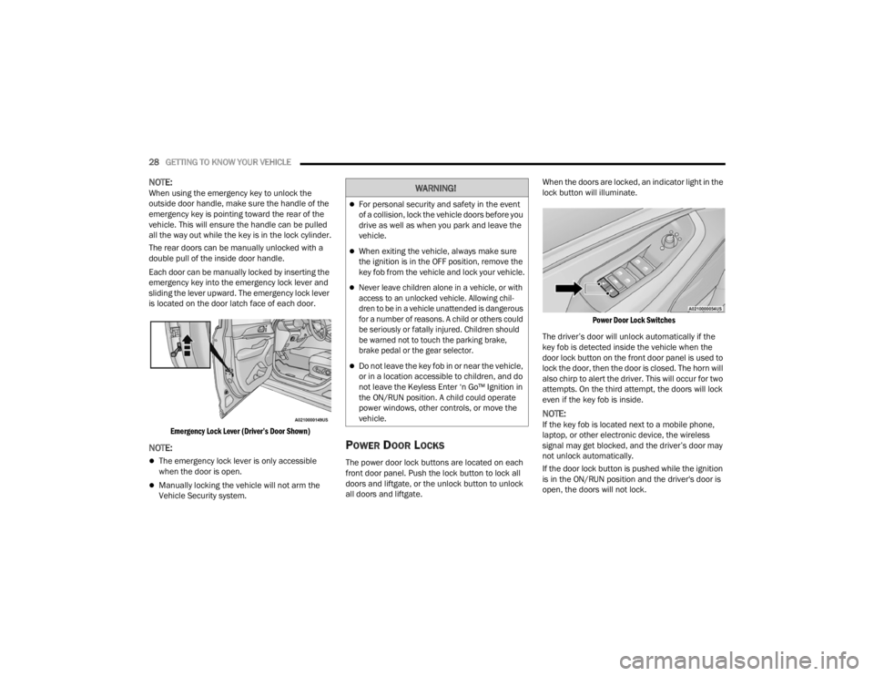
Each door can be manually locked by inserting the
emergency key into the emergency lock lever and
sliding the lever upward. The emergency lock lever
is located on the door latch face of each door.
Emergency Lock Lever (Driver’s Door Shown)
NOTE:
The emergency lock lever is only accessible
when the door is open.
Manually locking the vehicle will not arm the
Vehicle Security system.
POWER DOOR LOCKS
The power door lock buttons are located on each
front door panel. Push the lock button to lock all
doors and liftgate, or the unlock button to unlock
all doors and liftgate. When the doors are locked, an indicator light in the
lock button will illuminate.
Power Door Lock Switches
The driver’s door will unlock automatically if the
key fob is detected inside the vehicle when the
door lock button on the front door panel is used to
lock the door, then the door is closed. The horn will
also chirp to alert the driver. This will occur for two
attempts. On the third attempt, the doors will lock
even if the key fob is inside.
NOTE:If the key fob is located next to a mobile phone,
laptop, or other electronic device, the wireless
signal may get blocked, and the driver’s door may
not unlock automatically.
If the door lock button is pushed while the ignition
is in the ON/RUN position and the driver's door is
open, the doors will not lock.
WARNING!
For personal security and safety in the event
of a collision, lock the vehicle doors before you
drive as well as when you park and leave the
vehicle.
When exiting the vehicle, always make sure
the ignition is in the OFF position, remove the
key fob from the vehicle and lock your vehicle.
Never leave children alone in a vehicle, or with
access to an unlocked vehicle. Allowing chil -
dren to be in a vehicle unattended is dangerous
for a number of reasons. A child or others could
be seriously or fatally injured. Children should
be warned not to touch the parking brake,
brake pedal or the gear selector.
Do not leave the key fob in or near the vehicle,
or in a location accessible to children, and do
not leave the Keyless Enter ‘n Go™ Ignition in
the ON/RUN position. A child could operate
power windows, other controls, or move the
vehicle.
23_WL_OM_EN_USC_t.book Page 28
Page 60 of 424
58GETTING TO KNOW YOUR VEHICLE
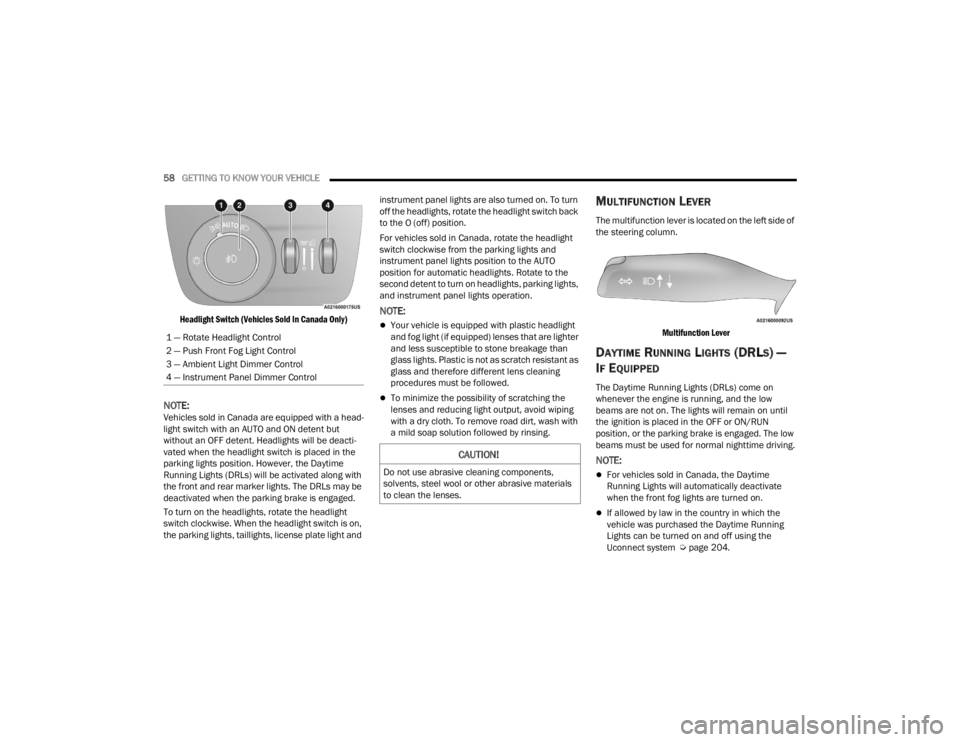
Headlight Switch (Vehicles Sold In Canada Only)
NOTE:Vehicles sold in Canada are equipped with a head -
light switch with an AUTO and ON detent but
without an OFF detent. Headlights will be deacti -
vated when the headlight switch is placed in the
parking lights position. However, the Daytime
Running Lights (DRLs) will be activated along with
the front and rear marker lights. The DRLs may be
deactivated when the parking brake is engaged.
To turn on the headlights, rotate the headlight
switch clockwise. When the headlight switch is on,
the parking lights, taillights, license plate light and instrument panel lights are also turned on. To turn
off the headlights, rotate the headlight switch back
to the O (off) position.
For vehicles sold in Canada, rotate the headlight
switch clockwise from the parking lights and
instrument panel lights position to the AUTO
position for automatic headlights. Rotate to the
second detent to turn on headlights, parking lights,
and instrument panel lights operation.
NOTE:
Your vehicle is equipped with plastic headlight
and fog light (if equipped) lenses that are lighter
and less susceptible to stone breakage than
glass lights. Plastic is not as scratch resistant as
glass and therefore different lens cleaning
procedures must be followed.
To minimize the possibility of scratching the
lenses and reducing light output, avoid wiping
with a dry cloth. To remove road dirt, wash with
a mild soap solution followed by rinsing.
MULTIFUNCTION LEVER
The multifunction lever is located on the left side of
the steering column.
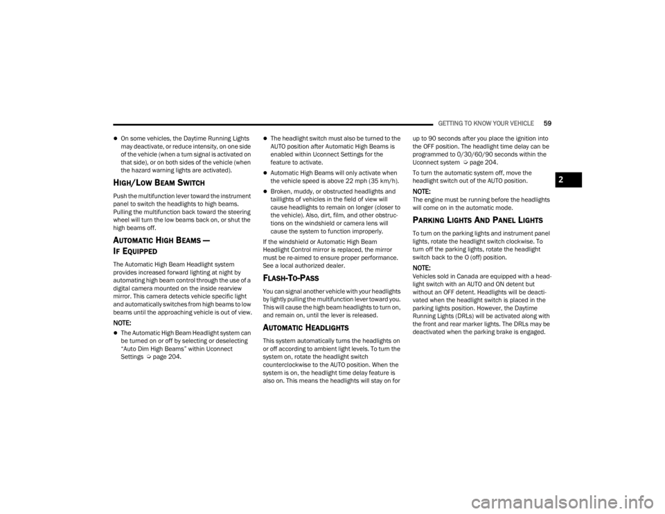
Multifunction Lever
DAYTIME RUNNING LIGHTS (DRLS) —
I
F EQUIPPED
The Daytime Running Lights (DRLs) come on
whenever the engine is running, and the low
beams are not on. The lights will remain on until
the ignition is placed in the OFF or ON/RUN
position, or the parking brake is engaged. The low
beams must be used for normal nighttime driving.
NOTE:
For vehicles sold in Canada, the Daytime
Running Lights will automatically deactivate
when the front fog lights are turned on.
If allowed by law in the country in which the
vehicle was purchased the Daytime Running
Lights can be turned on and off using the
Uconnect system Ú page 204.
1 — Rotate Headlight Control
2 — Push Front Fog Light Control
3 — Ambient Light Dimmer Control
4 — Instrument Panel Dimmer Control
CAUTION!
Do not use abrasive cleaning components,
solvents, steel wool or other abrasive materials
to clean the lenses.
23_WL_OM_EN_USC_t.book Page 58
Page 61 of 424
GETTING TO KNOW YOUR VEHICLE59
On some vehicles, the Daytime Running Lights
may deactivate, or reduce intensity, on one side
of the vehicle (when a turn signal is activated on
that side), or on both sides of the vehicle (when
the hazard warning lights are activated).
HIGH/LOW BEAM SWITCH
Push the multifunction lever toward the instrument
panel to switch the headlights to high beams.
Pulling the multifunction back toward the steering
wheel will turn the low beams back on, or shut the
high beams off.
AUTOMATIC HIGH BEAMS —
I
F EQUIPPED
The Automatic High Beam Headlight system
provides increased forward lighting at night by
automating high beam control through the use of a
digital camera mounted on the inside rearview
mirror. This camera detects vehicle specific light
and automatically switches from high beams to low
beams until the approaching vehicle is out of view.
NOTE:
The Automatic High Beam Headlight system can
be turned on or off by selecting or deselecting
“Auto Dim High Beams” within Uconnect
Settings Ú page 204.
The headlight switch must also be turned to the
AUTO position after Automatic High Beams is
enabled within Uconnect Settings for the
feature to activate.
Automatic High Beams will only activate when
the vehicle speed is above 22 mph (35 km/h).
Broken, muddy, or obstructed headlights and
taillights of vehicles in the field of view will
cause headlights to remain on longer (closer to
the vehicle). Also, dirt, film, and other obstruc -
tions on the windshield or camera lens will
cause the system to function improperly.
If the windshield or Automatic High Beam
Headlight Control mirror is replaced, the mirror
must be re-aimed to ensure proper performance.
See a local authorized dealer.
FLASH-TO-PASS
You can signal another vehicle with your headlights
by lightly pulling the multifunction lever toward you.
This will cause the high beam headlights to turn on,
and remain on, until the lever is released.
AUTOMATIC HEADLIGHTS
This system automatically turns the headlights on
or off according to ambient light levels. To turn the
system on, rotate the headlight switch
counterclockwise to the AUTO position. When the
system is on, the headlight time delay feature is
also on. This means the headlights will stay on for up to 90 seconds after you place the ignition into
the OFF position. The headlight time delay can be
programmed to 0/30/60/90 seconds within the
Uconnect system Ú
page 204.
To turn the automatic system off, move the
headlight switch out of the AUTO position.
NOTE:The engine must be running before the headlights
will come on in the automatic mode.
PARKING LIGHTS AND PANEL LIGHTS
To turn on the parking lights and instrument panel
lights, rotate the headlight switch clockwise. To
turn off the parking lights, rotate the headlight
switch back to the O (off) position.
NOTE:Vehicles sold in Canada are equipped with a head -
light switch with an AUTO and ON detent but
without an OFF detent. Headlights will be deacti -
vated when the headlight switch is placed in the
parking lights position. However, the Daytime
Running Lights (DRLs) will be activated along with
the front and rear marker lights. The DRLs may be
deactivated when the parking brake is engaged.
2
23_WL_OM_EN_USC_t.book Page 59
Page 103 of 424
GETTING TO KNOW YOUR INSTRUMENT PANEL101
Vehicles Equipped With Keyless Enter ‘n Go™
Ignition
Use the steering wheel instrument cluster display
controls for the following procedure(s):
1. Without pressing the brake pedal, push the ENGINE START/STOP button and place the
ignition in the ON/RUN position (do not start
the engine).
2. Push and release the down arrow button to
scroll downward through the main menu to
“Vehicle Info”.
3. Push and release the right arrow button to access the “Oil Life” screen.
4. Push and hold the OK button to reset oil life. If
conditions are met, the gauge and numeric
display will update to show 100%. If conditions
are not met a pop-up message of “To reset oil
life engine must be off with ignition in run” will
be displayed (for five seconds), and the user
will remain at the Oil Life screen.
5. Push and release the up or down arrow
button to exit the submenu screen.
NOTE:If the indicator message illuminates when you start
the vehicle, the oil change indicator system did not
reset. If necessary, repeat this procedure. Secondary Method Of Resetting Engine Oil Life
1. Without pressing the brake pedal, push the
ENGINE START/STOP button and place the
ignition to the ON/RUN position (do not start
the engine).
2. Fully press the accelerator pedal, slowly, three times within 10 seconds.
3. Without pushing the brake pedal, push the ENGINE START/STOP button once to return the
ignition to the OFF position.
NOTE:If the indicator message illuminates when you start
the vehicle, the oil change indicator system did not
reset. If necessary, repeat this procedure.
DISPLAY AND MESSAGES
The instrument cluster display is located in the
center portion of the cluster and consist of multiple
sections:
Main Screen — The inner ring of the display will
illuminate in black under normal conditions,
yellow for non critical warnings and red for crit -
ical warnings
Submenu Dots — Whenever there are
submenus available, the position within the
submenus is shown here
Reconfigurable Telltales/Information
Gear Selector Status (PRND)
Driver Interactive Display (Compass, Temp,
Range to Empty, Trip A, Trip B, Average Fuel
Economy, Current Fuel Economy and Time)
Air Suspension Status — If Equipped
Four-Wheel Drive (4WD) Status — If Equipped
The instrument cluster display will normally display
the main menu or the screens of a selected feature
of the main menu. The main display area also
displays pop-up messages and warning or
information messages. These pop-up messages
fall into several categories:
Five Second Stored Messages
When the appropriate conditions occur, this
type of message takes control of the main
display area for five seconds and then returns to
the previous screen. Most of the messages of
this type are then stored (as long as the condi-
tion that activated it remains active) and can be
reviewed from the “Messages” main menu item.
Examples of this message type are “Right Front
Turn Signal Lamp Out” and “Low Tire Pressure”.
Unstored Messages
This message type is displayed indefinitely or
until the condition that activated the message is
cleared. Examples of this message type are
“Turn Signal On” (if a turn signal is left on) and
“Lights On” (if driver leaves the vehicle with the
lights on).
3
23_WL_OM_EN_USC_t.book Page 101
Page 104 of 424
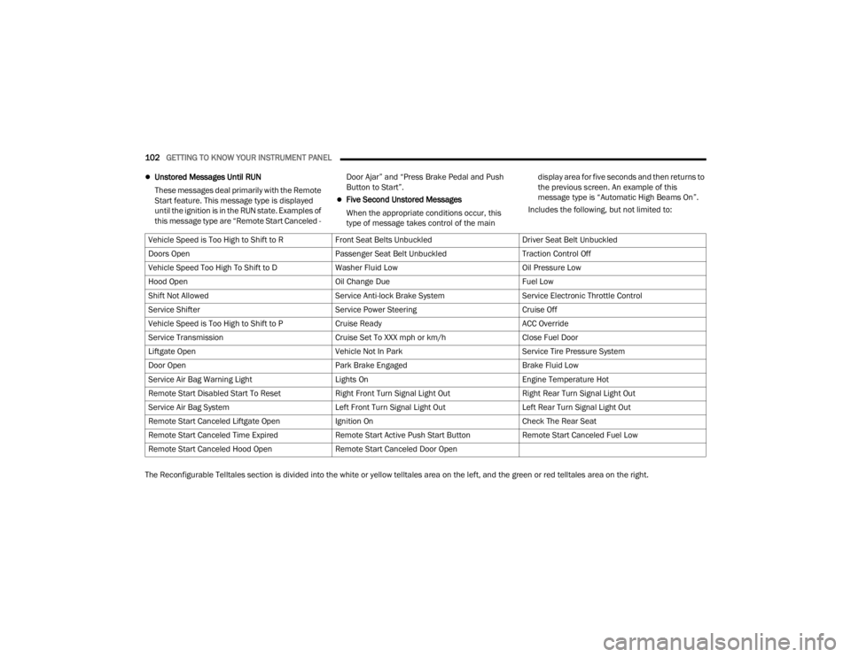
102GETTING TO KNOW YOUR INSTRUMENT PANEL
Unstored Messages Until RUN
These messages deal primarily with the Remote
Start feature. This message type is displayed
until the ignition is in the RUN state. Examples of
this message type are “Remote Start Canceled - Door Ajar” and “Press Brake Pedal and Push
Button to Start”.
Five Second Unstored Messages
When the appropriate conditions occur, this
type of message takes control of the main display area for five seconds and then returns to
the previous screen. An example of this
message type is “Automatic High Beams On”.
Includes the following, but not limited to:
The Reconfigurable Telltales section is divided into the white or yellow telltales area on the left, and the green or red telltales area on the right. Vehicle Speed is Too High to Shift to R
Front Seat Belts UnbuckledDriver Seat Belt Unbuckled
Doors Open Passenger Seat Belt UnbuckledTraction Control Off
Vehicle Speed Too High To Shift to D Washer Fluid LowOil Pressure Low
Hood Open Oil Change DueFuel Low
Shift Not Allowed Service Anti-lock Brake SystemService Electronic Throttle Control
Service Shifter Service Power SteeringCruise Off
Vehicle Speed is Too High to Shift to P Cruise ReadyACC Override
Service Transmission Cruise Set To XXX mph or km/hClose Fuel Door
Liftgate Open Vehicle Not In ParkService Tire Pressure System
Door Open Park Brake EngagedBrake Fluid Low
Service Air Bag Warning Light Lights OnEngine Temperature Hot
Remote Start Disabled Start To Reset Right Front Turn Signal Light OutRight Rear Turn Signal Light Out
Service Air Bag System Left Front Turn Signal Light OutLeft Rear Turn Signal Light Out
Remote Start Canceled Liftgate Open Ignition OnCheck The Rear Seat
Remote Start Canceled Time Expired Remote Start Active Push Start ButtonRemote Start Canceled Fuel Low
Remote Start Canceled Hood Open Remote Start Canceled Door Open
23_WL_OM_EN_USC_t.book Page 102
Page 110 of 424
108GETTING TO KNOW YOUR INSTRUMENT PANEL
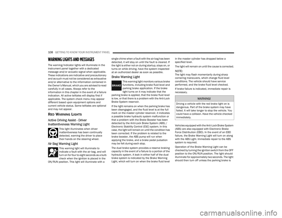
WARNING LIGHTS AND MESSAGES
The warning/indicator lights will illuminate in the
instrument panel together with a dedicated
message and/or acoustic signal when applicable.
These indications are indicative and precautionary
and as such must not be considered as exhaustive
and/or alternative to the information contained in
the Owner’s Manual, which you are advised to read
carefully in all cases. Always refer to the
information in this chapter in the event of a failure
indication. All active telltales will display first if
applicable. The system check menu may appear
different based upon equipment options and
current vehicle status. Some telltales are optional
and may not appear.
RED WARNING LIGHTS
Active Driving Assist - Driver
Inattentiveness Warning Light
This light illuminates when driver
inattentiveness has been continually
detected, warning the driver to place
their hands on the steering wheel.
Air Bag Warning Light
This warning light will illuminate to
indicate a fault with the air bag, and will
turn on for four to eight seconds as a bulb
check when the ignition is placed in the
ON/RUN position. This light will illuminate with a single chime when a fault with the air bag has been
detected, it will stay on until the fault is cleared. If
the light is either not on during startup, stays on, or
turns on while driving, have the system inspected
at an authorized dealer as soon as possible.
Brake Warning Light
This warning light monitors various brake
functions, including brake fluid level and
parking brake application. If the brake
light turns on it may indicate that the
parking brake is applied, that the brake fluid level
is low, or that there is a problem with the Anti-Lock
Brake System reservoir.
If the light remains on when the parking brake has
been disengaged, and the fluid level is at the full
mark on the master cylinder reservoir, it indicates
a possible brake hydraulic system malfunction or
that a problem with the Brake Booster has been
detected by the Anti-Lock Brake System (ABS) /
Electronic Stability Control (ESC) system. In this
case, the light will remain on until the condition has
been corrected. If the problem is related to the
brake booster, the ABS pump will run when
applying the brake, and a brake pedal pulsation
may be felt during each stop.
The dual brake system provides a reserve braking
capacity in the event of a failure to a portion of the
hydraulic system. A leak in either half of the dual
brake system is indicated by the Brake Warning
Light, which will turn on when the brake fluid level in the master cylinder has dropped below a
specified level.
The light will remain on until the cause is corrected.
NOTE:The light may flash momentarily during sharp
cornering maneuvers, which change fluid level
conditions. The vehicle should have service
performed, and the brake fluid level checked.
If brake failure is indicated, immediate repair is
necessary.
Vehicles equipped with the Anti-Lock Brake System
(ABS) are also equipped with Electronic Brake
Force Distribution (EBD). In the event of an EBD
failure, the Brake Warning Light will turn on along
with the ABS Light. Immediate repair to the ABS
system is required.
Operation of the Brake Warning Light can be
checked by turning the ignition switch from the OFF
position to the ON/RUN position. The light should
illuminate for approximately two seconds. The light
should then turn off unless the parking brake is
WARNING!
Driving a vehicle with the red brake light on is
dangerous. Part of the brake system may have
failed. It will take longer to stop the vehicle. You
could have a collision. Have the vehicle checked
immediately.
23_WL_OM_EN_USC_t.book Page 108