maintenance JEEP GRAND CHEROKEE 2023 Owners Manual
[x] Cancel search | Manufacturer: JEEP, Model Year: 2023, Model line: GRAND CHEROKEE, Model: JEEP GRAND CHEROKEE 2023Pages: 424, PDF Size: 15.48 MB
Page 3 of 424
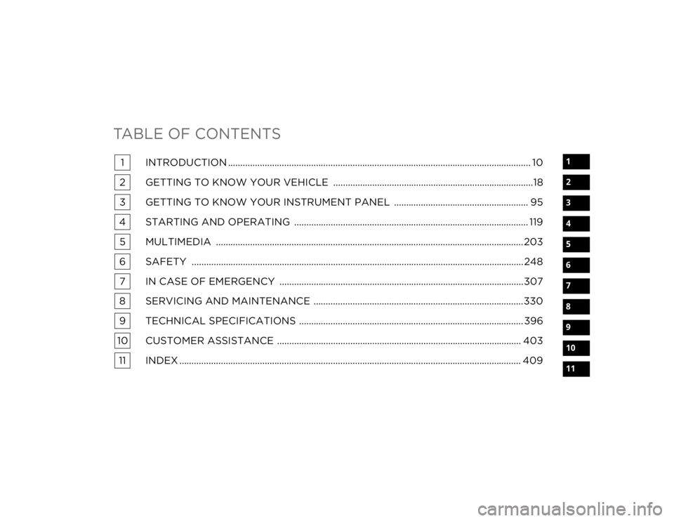
TABLE OF CONTENTS
1
2
3
4
5
6
7
8
9
10
11
1 INTRODUCTION ............................................................................................................................ 10
2 GETTING TO KNOW YOUR VEHICLE ..................................................................................18
3 GETTING TO KNOW YOUR INSTRUMENT PANEL ....................................................... 95
4 STARTING AND OPERATING ................................................................................................ 119 5 MULTIMEDIA .............................................................................................................................. 203
6 SAFETY ........................................................................................................................................ 248 7 IN CASE OF EMERGENCY ....................................................................................................307
8 SERVICING AND MAINTENANCE ......................................................................................330
9 TECHNICAL SPECIFICATIONS ............................................................................................ 396
10 CUSTOMER ASSISTANCE .................................................................................................... 403 11 INDEX ............................................................................................................................................ 409
23_WL_OM_EN_USC_t.book Page 1
Page 6 of 424
4
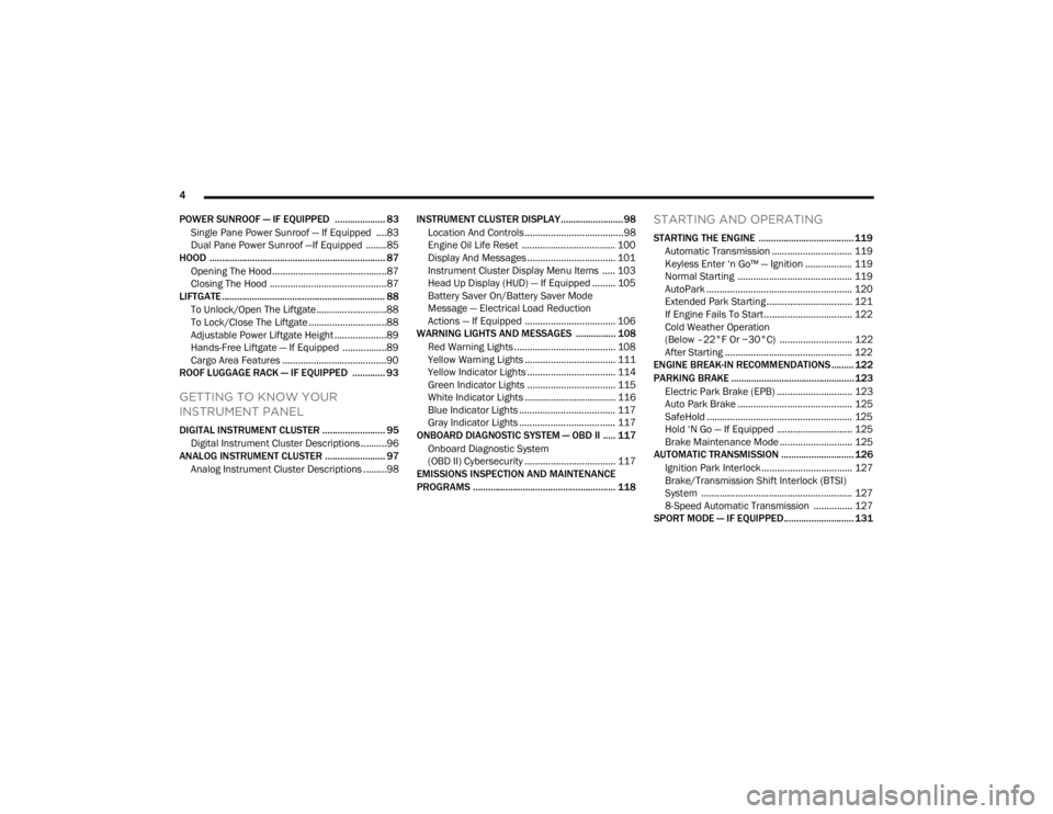
POWER SUNROOF — IF EQUIPPED .................... 83 Single Pane Power Sunroof — If Equipped ....83
Dual Pane Power Sunroof —If Equipped ........85
HOOD ...................................................................... 87
Opening The Hood............................................87
Closing The Hood .............................................87
LIFTGATE ................................................................. 88
To Unlock/Open The Liftgate...........................88
To Lock/Close The Liftgate ..............................88
Adjustable Power Liftgate Height ....................89
Hands-Free Liftgate — If Equipped .................89
Cargo Area Features ........................................90
ROOF LUGGAGE RACK — IF EQUIPPED ............. 93
GETTING TO KNOW YOUR
INSTRUMENT PANEL
DIGITAL INSTRUMENT CLUSTER ......................... 95
Digital Instrument Cluster Descriptions ..........96
ANALOG INSTRUMENT CLUSTER ........................ 97
Analog Instrument Cluster Descriptions .........98 INSTRUMENT CLUSTER DISPLAY.........................98
Location And Controls ......................................98
Engine Oil Life Reset .................................... 100
Display And Messages .................................. 101
Instrument Cluster Display Menu Items ..... 103
Head Up Display (HUD) — If Equipped ......... 105Battery Saver On/Battery Saver Mode
Message — Electrical Load Reduction
Actions — If Equipped ................................... 106
WARNING LIGHTS AND MESSAGES ................ 108
Red Warning Lights ....................................... 108
Yellow Warning Lights ................................... 111Yellow Indicator Lights .................................. 114
Green Indicator Lights .................................. 115
White Indicator Lights ................................... 116Blue Indicator Lights ..................................... 117
Gray Indicator Lights ..................................... 117
ONBOARD DIAGNOSTIC SYSTEM — OBD II ..... 117
Onboard Diagnostic System
(OBD II) Cybersecurity ................................... 117
EMISSIONS INSPECTION AND MAINTENANCE
PROGRAMS ......................................................... 118
STARTING AND OPERATING
STARTING THE ENGINE ...................................... 119
Automatic Transmission ............................... 119
Keyless Enter ‘n Go™ — Ignition .................. 119
Normal Starting ............................................ 119
AutoPark ........................................................ 120
Extended Park Starting ................................. 121
If Engine Fails To Start .................................. 122Cold Weather Operation
(Below –22°F Or −30°C) ............................ 122
After Starting ................................................. 122
ENGINE BREAK-IN RECOMMENDATIONS ......... 122
PARKING BRAKE ................................................. 123
Electric Park Brake (EPB) ............................. 123Auto Park Brake ............................................ 125
SafeHold ........................................................ 125
Hold ‘N Go — If Equipped ............................. 125Brake Maintenance Mode ............................ 125
AUTOMATIC TRANSMISSION ............................. 126
Ignition Park Interlock................................... 127
Brake/Transmission Shift Interlock (BTSI)
System .......................................................... 1278-Speed Automatic Transmission ............... 127
SPORT MODE — IF EQUIPPED............................ 131
23_WL_OM_EN_USC_t.book Page 4
Page 10 of 424
8
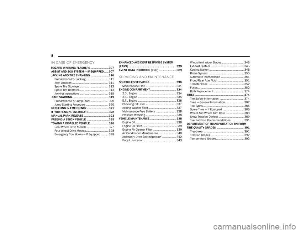
IN CASE OF EMERGENCY
HAZARD WARNING FLASHERS ......................... 307
ASSIST AND SOS SYSTEM — IF EQUIPPED ...... 307
JACKING AND TIRE CHANGING ........................ 310 Preparations For Jacking .............................. 311Jack Location ................................................. 311
Spare Tire Stowage ...................................... 313Spare Tire Removal ....................................... 313
Jacking Instructions ...................................... 315
JUMP STARTING................................................... 319
Preparations For Jump Start......................... 320Jump Starting Procedure .............................. 320
REFUELING IN EMERGENCY .............................. 321
IF YOUR ENGINE OVERHEATS ............................ 322
MANUAL PARK RELEASE .................................. 323
FREEING A STUCK VEHICLE .............................. 325
TOWING A DISABLED VEHICLE .......................... 326
Rear-Wheel Drive Models ............................. 327
Four-Wheel Drive Models.............................. 328Emergency Tow Hooks — If Equipped .......... 328 ENHANCED ACCIDENT RESPONSE SYSTEM
(EARS) .................................................................. 329
EVENT DATA RECORDER (EDR) ........................ 329
SERVICING AND MAINTENANCE
SCHEDULED SERVICING ................................... 330
Maintenance Plan ......................................... 331
ENGINE COMPARTMENT .................................... 334
2.0L Engine .................................................. 334
3.6L Engine ................................................... 335
5.7L Engine ................................................... 336
Checking Oil Level ........................................ 337Adding Washer Fluid ..................................... 337
Maintenance-Free Battery ........................... 338Pressure Washing ......................................... 338
VEHICLE MAINTENANCE..................................... 338
Engine Oil ....................................................... 338
Engine Oil Filter ............................................. 339Engine Air Cleaner Filter ............................... 339
Air Conditioner Maintenance ....................... 340
Accessory Drive Belt Inspection ................... 342Body Lubrication ........................................... 343 Windshield Wiper Blades.............................. 343
Exhaust System ............................................ 345
Cooling System.............................................. 346
Brake System ............................................... 350
Automatic Transmission ............................... 351
Front/Rear Axle Fluid ................................... 351
Transfer Case ............................................... 352Fuses.............................................................. 352
Bulb Replacement ........................................ 374
TIRES ..................................................................... 374
Tire Safety Information ................................ 374Tires — General Information ......................... 382
Tire Types....................................................... 385Spare Tires — If Equipped ............................ 386
Wheel And Wheel Trim Care ........................ 388Snow Traction Devices ................................. 389
Tire Rotation Recommendations ................ 391
DEPARTMENT OF TRANSPORTATION UNIFORM
TIRE QUALITY GRADES ...................................... 391
Treadwear...................................................... 391
Traction Grades ............................................. 392Temperature Grades..................................... 392
23_WL_OM_EN_USC_t.book Page 8
Page 11 of 424
9
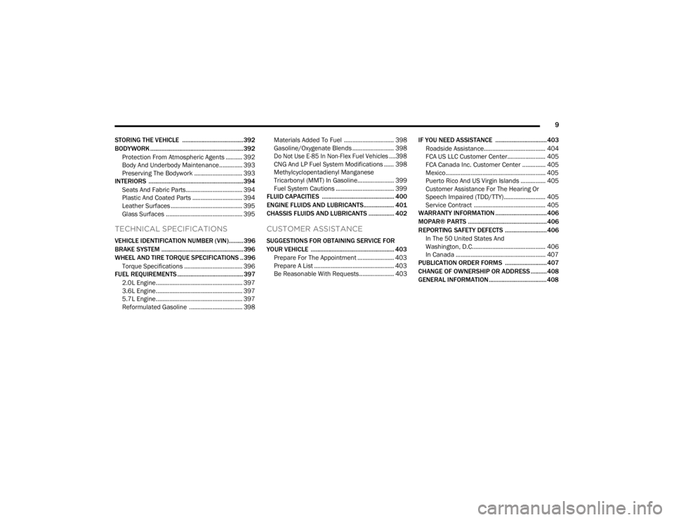
STORING THE VEHICLE ...................................... 392
BODYWORK .......................................................... 392 Protection From Atmospheric Agents .......... 392
Body And Underbody Maintenance.............. 393
Preserving The Bodywork ............................. 393
INTERIORS ........................................................... 394
Seats And Fabric Parts.................................. 394
Plastic And Coated Parts .............................. 394Leather Surfaces ........................................... 395Glass Surfaces .............................................. 395
TECHNICAL SPECIFICATIONS
VEHICLE IDENTIFICATION NUMBER (VIN)......... 396
BRAKE SYSTEM ................................................... 396
WHEEL AND TIRE TORQUE SPECIFICATIONS .. 396
Torque Specifications ................................... 396
FUEL REQUIREMENTS ......................................... 397
2.0L Engine.................................................... 397
3.6L Engine.................................................... 397
5.7L Engine.................................................... 397
Reformulated Gasoline ................................ 398 Materials Added To Fuel .............................. 398
Gasoline/Oxygenate Blends ......................... 398
Do Not Use E-85 In Non-Flex Fuel Vehicles ....398
CNG And LP Fuel System Modifications ...... 398Methylcyclopentadienyl Manganese
Tricarbonyl (MMT) In Gasoline...................... 399Fuel System Cautions ................................... 399
FLUID CAPACITIES ............................................. 400
ENGINE FLUIDS AND LUBRICANTS................... 401
CHASSIS FLUIDS AND LUBRICANTS ................ 402
CUSTOMER ASSISTANCE
SUGGESTIONS FOR OBTAINING SERVICE FOR
YOUR VEHICLE .................................................... 403
Prepare For The Appointment ...................... 403Prepare A List ................................................ 403Be Reasonable With Requests..................... 403 IF YOU NEED ASSISTANCE ................................ 403
Roadside Assistance..................................... 404FCA US LLC Customer Center....................... 405
FCA Canada Inc. Customer Center .............. 405
Mexico............................................................ 405
Puerto Rico And US Virgin Islands ............... 405
Customer Assistance For The Hearing Or
Speech Impaired (TDD/TTY) ......................... 405
Service Contract ........................................... 405
WARRANTY INFORMATION ................................ 406
MOPAR® PARTS ................................................. 406
REPORTING SAFETY DEFECTS .......................... 406
In The 50 United States And
Washington, D.C............................................ 406
In Canada ...................................................... 407
PUBLICATION ORDER FORMS .......................... 407
CHANGE OF OWNERSHIP OR ADDRESS .......... 408
GENERAL INFORMATION.................................... 408
23_WL_OM_EN_USC_t.book Page 9
Page 86 of 424
84GETTING TO KNOW YOUR VEHICLE
Opening And Closing The Sunroof
Express Open/Close
To open the sunroof, push OPEN on the sunroof
switch and release it within one-half second and
the sunroof will open automatically from any
position.
To close the sunroof, push CLOSE on the sunroof
switch and release it within one-half second and
the sunroof will close automatically from any
position.
During Express Open or Express Close operation,
any other actuation of the sunroof switch will stop
the sunroof.
Manual Open/Close
To open the sunroof, push and hold OPEN on the
sunroof switch.
To close the sunroof, push and hold CLOSE on the
sunroof switch.
Any release of the switch during open or close
operation will stop the sunroof movement in a
partially open position. The sunroof will remain in a
partially opened position until the switch is
operated and held again. Express Venting The Sunroof
To vent the sunroof, push TILT on the vent switch
and release within one half second. The sunroof
will open to the vent position regardless of its initial
position. During Express Vent operation, any other
actuation of the switch will stop the sunroof.
NOTE:If the sunshade is in the closed position when
Express/Manual Open or Vent operation is
initiated, the sunshade will automatically open
with the sunroof glass.
Pinch Protect Feature
This feature will detect an obstruction in the
opening of the sunroof during Express Close
operation. If an obstruction in the path of the
sunroof is detected, the sunroof will automatically
retract. Remove the obstruction if this occurs.
NOTE:If three consecutive sunroof close attempts result
in Pinch Protect reversals, Pinch Protect will
disable and the sunroof must be closed in Manual
Mode.
Sunshade Operation
The sunshade can be opened manually. However,
the sunshade will open automatically as the
sunroof opens.
NOTE:The sunshade cannot be closed if the sunroof is
open.
Ignition Off Operation
The power sunroof switch will remain active for up
to approximately 10 minutes after the ignition
switch is placed in the OFF position. Opening either
front door will cancel this feature.
NOTE:Ignition Off timing is programmable through the
Uconnect system Ú
page 204.
Sunroof Maintenance
Use only a non-abrasive cleaner and a soft cloth to
clean the glass panel. Periodically check for and
clear out any debris that may have collected in the
tracks.
23_WL_OM_EN_USC_t.book Page 84
Page 88 of 424
86GETTING TO KNOW YOUR VEHICLE
Express Venting The Sunroof
To vent the sunroof, push TILT on the vent switch
and release within one half second. The sunroof
will open to the vent position regardless of its initial
position. During Express Vent operation, any other
actuation of the switch will stop the sunroof.
NOTE:If the sunshade is in the closed position when
Express/Manual Open or Vent operation is
initiated, the sunshade will automatically open to
the half open position prior to the sunroof opening.
Opening And Closing The Power Sunshade
The sunshade has two programmed open
positions: half open and full open positions. When
operating the sunshade from the closed position,
the sunshade will always stop at the half open
position regardless of express or manual open
operation. The switch must be pushed again to
continue on to full open position.
If the sunroof is open or vented, the sunshade
cannot be closed beyond the half open position.
Pushing the sunshade close switch when the
sunroof is open/vented and the sunshade is at half
open position will first automatically close the
sunroof prior to the sunshade closing. Express Open/Close
To open the sunshade, push OPEN on the
sunshade switch and release it within one-half
second, the sunshade will open to the half open
position and stop automatically. Push and release
OPEN again to continue to open the sunshade to
the full open position.
To close the sunshade, push CLOSE on the
sunshade switch and release it within one-half
second.
During Express Open or Express Close operation,
any other actuation of the sunroof switches will
stop the sunshade in a partially open position.
Manual Open/Close
To open the sunshade, push and hold OPEN on the
sunshade switch, the sunshade will open to the
half open position and stop automatically. Push
and hold OPEN again to continue to open the
sunshade to the full open position.
To close the sunshade, push and hold CLOSE on
the sunshade switch.
Releasing the switch while the sunshade is in
motion will stop the sunshade in a partially open
position.
Pinch Protect Feature
This feature will detect an obstruction in the
opening of the sunroof during Express Close
operation. If an obstruction in the path of the
sunroof is detected, the sunroof will automatically
retract. Remove the obstruction if this occurs.
NOTE:If three consecutive sunroof close attempts result
in Pinch Protect reversals, Pinch Protect will
disable and the sunroof must be closed in Manual
Mode.
Ignition Off Operation
The power sunroof switch will remain active for up
to approximately 10 minutes after the ignition
switch is placed in the OFF position. Opening either
front door will cancel this feature.
NOTE:Ignition Off timing is programmable through the
Uconnect system Ú
page 204.
Sunroof Maintenance
Use only a non-abrasive cleaner and a soft cloth to
clean the glass panel. Periodically check for and
clear out any debris that may have collected in the
tracks.
23_WL_OM_EN_USC_t.book Page 86
Page 102 of 424
100GETTING TO KNOW YOUR INSTRUMENT PANEL
Custom Tile Configuration
To customize the instrument cluster further, you
are able to select up to five tiles to display
information based on your needs.
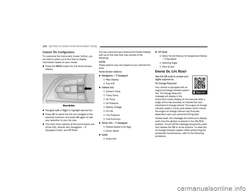
Press the MENU button for the Home Screen
display
Menu Button
Navigate Left or Right to highlight desired tile
Press OK to select the tile and navigate to the
selected submenu and press OK again to add
your selection to your tile view
The main menu options of the home screen are
Driver Info, Vehicle Info, Navigation — If
Equipped, Audio, and Off Road You can customize your Instrument Cluster Display
with up to five tiles that may consist of the
following:
NOTE:These options may vary based on your vehicle trim
level.
Home Screen Options
Navigation — If Equipped
Map Display
Trip A/B
Vehicle Info
Coolant Temp
Trans Temp
Oil Temp
Oil Pressure
Battery Voltage
Oil Life
Tire Pressure
Fuel Economy
Driver Info — If Equipped
Posted Speed Limit Sign
Driver Assist
Audio
Audio Info
Off Road
Selec-Terrain Status/ Air Suspension Status
— If Equipped
Steering Angle
Pitch & Roll
ENGINE OIL LIFE RESET
Use this QR code to access your
digital experience
.
Oil Change Required
Your vehicle is equipped with an
engine oil change indicator system.
The “Oil Change Required”
message will display in the
instrument cluster display for five seconds after a
single chime has sounded, to indicate the next
scheduled oil change interval. The engine oil change
indicator system is duty cycle based, which means
the engine oil change interval may fluctuate,
dependent upon your personal driving style.
Unless reset, this message will continue to display
each time the ignition is placed in the ON/RUN
position. To turn off the message temporarily, push
and release the OK or arrow buttons. To reset the
oil change indicator system (after performing the
scheduled maintenance), refer to the following
procedure.
23_WL_OM_EN_USC_t.book Page 100
Page 116 of 424
114GETTING TO KNOW YOUR INSTRUMENT PANEL
also reduces fuel efficiency and tire tread life, and
may affect the vehicle’s handling and stopping
ability.
Please note that the TPMS is not a substitute for
proper tire maintenance, and it is the driver’s
responsibility to maintain correct tire pressure,
even if underinflation has not reached the level to
trigger illumination of the TPMS low tire pressure
telltale.
Your vehicle has also been equipped with a TPMS
malfunction indicator to indicate when the system
is not operating properly. The TPMS malfunction
indicator is combined with the low tire pressure
telltale. When the system detects a malfunction,
the telltale will flash for approximately one minute
and then remain continuously illuminated. This
sequence will continue upon subsequent vehicle
start-ups as long as the malfunction exists. When
the malfunction indicator is illuminated, the
system may not be able to detect or signal low tire
pressure as intended. TPMS malfunctions may
occur for a variety of reasons, including the
installation of replacement or alternate tires or
wheels on the vehicle that prevent the TPMS from
functioning properly. Always check the TPMS
malfunction telltale after replacing one or more
tires or wheels on your vehicle to ensure that the
replacement or alternate tires and wheels allow
the TPMS to continue to function properly.
YELLOW INDICATOR LIGHTS
4WD Low Indicator Light — If Equipped
This light alerts the driver that the vehicle
is in the 4WD Low mode. The front and
rear driveshafts are mechanically locked
together forcing the front and rear
wheels to rotate at the same speed. Low range
provides a greater gear reduction ratio to provide
increased torque at the wheels Ú page 131.
Air Suspension Active Indicator Light —
If Equipped
This light will illuminate when the air
suspension system is actively adjusting
the ride height Úpage 136.
Air Suspension Aerodynamic Height
Indicator Light— If Equipped
This light will illuminate when the air
suspension system is set to the
Aerodynamic setting Ú page 136.
Air Suspension Entry/Exit Indicator Light—
If Equipped
This light will illuminate when the vehicle
is automatically lowered from ride height
position downward for easy entry and exit
of the vehicle.
Air Suspension Off-Road 1 Indicator Light —
If Equipped
This light will illuminate when the air
suspension system is set to the Off-Road
1 setting Úpage 136.
Air Suspension Off-Road 2 Indicator Light —
If Equipped
This light will illuminate when the air
suspension system is set to the Off-Road
2 setting Úpage 136.
CAUTION!
The TPMS has been optimized for the original
equipment tires and wheels. TPMS pressures
and warning have been established for the tire
size equipped on your vehicle. Undesirable
system operation or sensor damage may result
when using replacement equipment that is not
of the same size, type, and/or style. Aftermarket
wheels can cause sensor damage. Using
aftermarket tire sealants may cause the Tire
Pressure Monitoring System (TPMS) sensor to
become inoperable. After using an aftermarket
tire sealant it is recommended that you take
your vehicle to an authorized dealer to have your
sensor function checked.
23_WL_OM_EN_USC_t.book Page 114
Page 120 of 424
118GETTING TO KNOW YOUR INSTRUMENT PANEL
EMISSIONS INSPECTION AND
MAINTENANCE PROGRAMS
In some localities, it may be a legal requirement to
pass an inspection of your vehicle's emissions
control system. Failure to pass could prevent
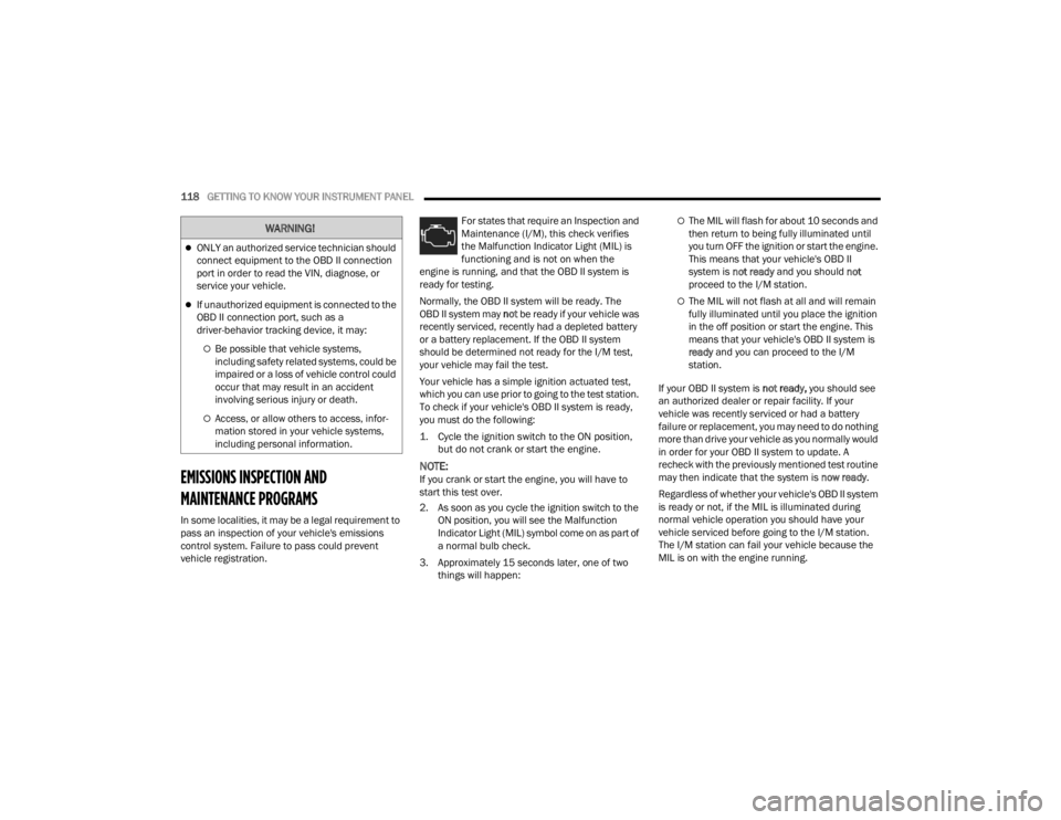
vehicle registration. For states that require an Inspection and
Maintenance (I/M), this check verifies
the Malfunction Indicator Light (MIL) is
functioning and is not on when the
engine is running, and that the OBD II system is
ready for testing.
Normally, the OBD II system will be ready. The
OBD II system may not be ready if your vehicle was
recently serviced, recently had a depleted battery
or a battery replacement. If the OBD II system
should be determined not ready for the I/M test,
your vehicle may fail the test.
Your vehicle has a simple ignition actuated test,
which you can use prior to going to the test station.
To check if your vehicle's OBD II system is ready,
you must do the following:
1. Cycle the ignition switch to the ON position, but do not crank or start the engine.
NOTE:If you crank or start the engine, you will have to
start this test over.
2. As soon as you cycle the ignition switch to the ON position, you will see the Malfunction
Indicator Light (MIL) symbol come on as part of
a normal bulb check.
3. Approximately 15 seconds later, one of two things will happen:
The MIL will flash for about 10 seconds and
then return to being fully illuminated until
you turn OFF the ignition or start the engine.
This means that your vehicle's OBD II
system is not ready and you should not
proceed to the I/M station.
The MIL will not flash at all and will remain
fully illuminated until you place the ignition
in the off position or start the engine. This
means that your vehicle's OBD II system is
ready and you can proceed to the I/M
station.
If your OBD II system is not ready, you should see
an authorized dealer or repair facility. If your
vehicle was recently serviced or had a battery
failure or replacement, you may need to do nothing
more than drive your vehicle as you normally would
in order for your OBD II system to update. A
recheck with the previously mentioned test routine
may then indicate that the system is now ready.
Regardless of whether your vehicle's OBD II system
is ready or not, if the MIL is illuminated during
normal vehicle operation you should have your
vehicle serviced before going to the I/M station.
The I/M station can fail your vehicle because the
MIL is on with the engine running.
WARNING!
ONLY an authorized service technician should
connect equipment to the OBD II connection
port in order to read the VIN, diagnose, or
service your vehicle.
If unauthorized equipment is connected to the
OBD II connection port, such as a
driver-behavior tracking device, it may:
Be possible that vehicle systems,
including safety related systems, could be
impaired or a loss of vehicle control could
occur that may result in an accident
involving serious injury or death.
Access, or allow others to access, infor -
mation stored in your vehicle systems,
including personal information.
23_WL_OM_EN_USC_t.book Page 118
Page 127 of 424
STARTING AND OPERATING125
AUTO PARK BRAKE
The EPB can be programmed to be applied
automatically whenever the vehicle is at a
standstill and the transmission is placed in PARK.
Auto Park Brake is enabled and disabled by
customer selection through the customer
programmable features section of the Uconnect
Settings Úpage 218.
Any single Auto Park Brake application can be
bypassed by pushing the EPB switch to the release
position while the transmission is placed in PARK.
SAFEHOLD
SafeHold is a safety feature of the EPB system that
will place the transmission in PARK, and engage
the parking brake automatically if the vehicle is left
unsecured while the ignition is in ON/RUN.
The parking brake will automatically engage if all of
the following conditions are met:
The vehicle is at a standstill.
There is no attempt to press the brake pedal or
accelerator pedal.
The seat belt is unbuckled.
The driver door is open. SafeHold can be temporarily bypassed by pushing
the EPB switch while the driver door is open. Once
manually bypassed, SafeHold will be enabled
again once the vehicle reaches 12 mph (20 km/h)
or the ignition is turned to the OFF position and
back to ON again.
HOLD ‘N GO — IF EQUIPPED
Hold ‘N Go is a comfort feature that allows the
driver to remove their foot from the brake pedal
once the vehicle has come to a stop. The vehicle
must be held at a standstill for a predetermined
amount of time by hydraulic braking. The EPB will
then engage and continue to hold the vehicle at a
stop until the driver applies the accelerator pedal.
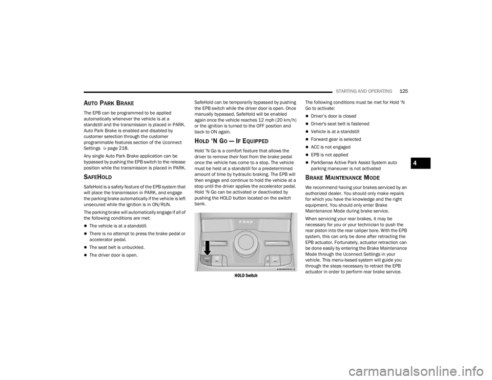
Hold ‘N Go can be activated or deactivated by
pushing the HOLD button located on the switch
bank.
HOLD Switch
The following conditions must be met for Hold ‘N
Go to activate:
Driver’s door is closed
Driver's seat belt is fastened
Vehicle is at a standstill
Forward gear is selected
ACC is not engaged
EPB is not applied
ParkSense Active Park Assist System auto
parking maneuver is not activated
BRAKE MAINTENANCE MODE
We recommend having your brakes serviced by an
authorized dealer. You should only make repairs
for which you have the knowledge and the right
equipment. You should only enter Brake
Maintenance Mode during brake service.
When servicing your rear brakes, it may be
necessary for you or your technician to push the
rear piston into the rear caliper bore. With the EPB
system, this can only be done after retracting the
EPB actuator. Fortunately, actuator retraction can
be done easily by entering the Brake Maintenance
Mode through the Uconnect Settings in your
vehicle. This menu-based system will guide you
through the steps necessary to retract the EPB
actuator in order to perform rear brake service.
4
23_WL_OM_EN_USC_t.book Page 125