sensor JEEP LIBERTY 2002 KJ / 1.G Workshop Manual
[x] Cancel search | Manufacturer: JEEP, Model Year: 2002, Model line: LIBERTY, Model: JEEP LIBERTY 2002 KJ / 1.GPages: 1803, PDF Size: 62.3 MB
Page 1162 of 1803
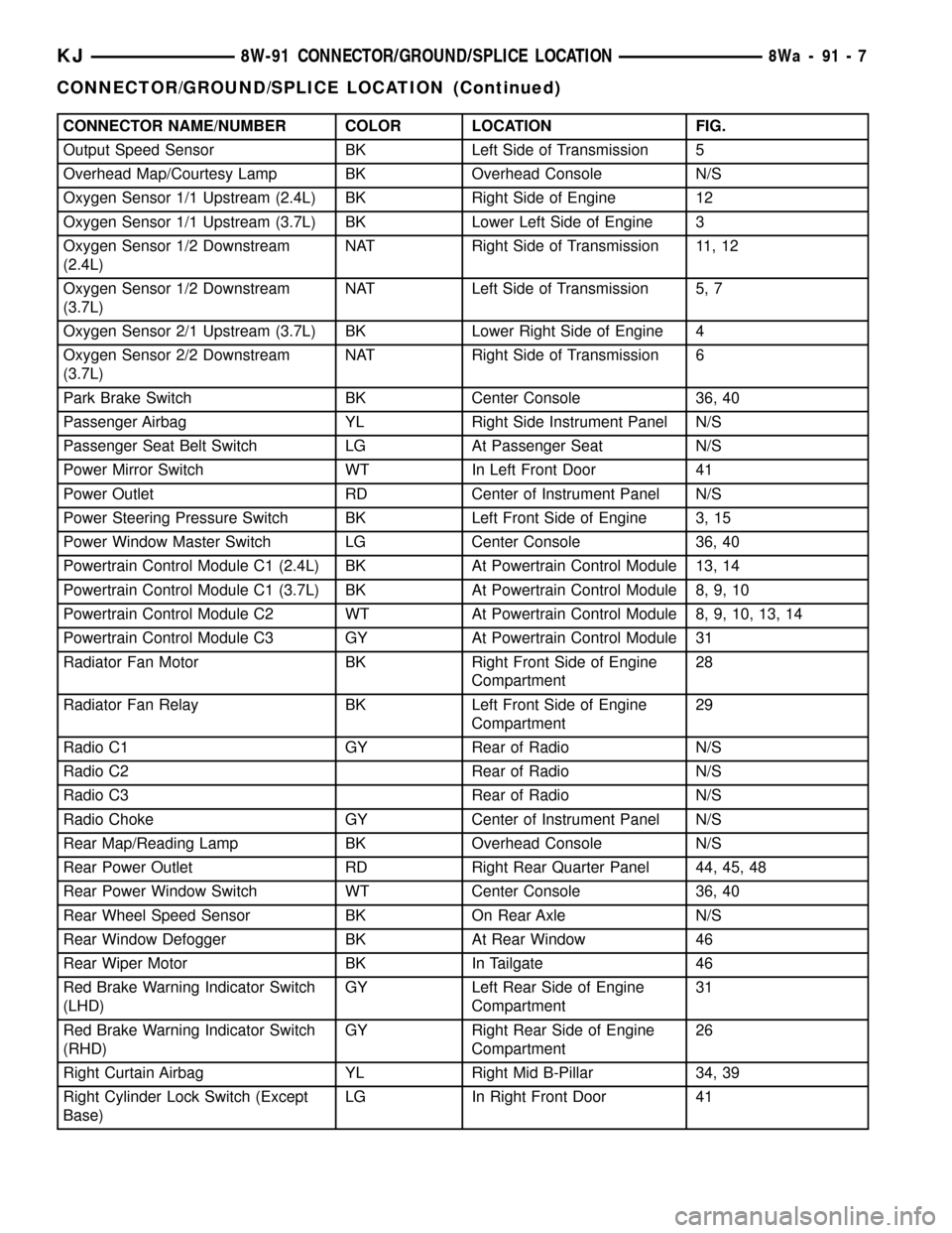
CONNECTOR NAME/NUMBER COLOR LOCATION FIG.
Output Speed Sensor BK Left Side of Transmission 5
Overhead Map/Courtesy Lamp BK Overhead Console N/S
Oxygen Sensor 1/1 Upstream (2.4L) BK Right Side of Engine 12
Oxygen Sensor 1/1 Upstream (3.7L) BK Lower Left Side of Engine 3
Oxygen Sensor 1/2 Downstream
(2.4L)NAT Right Side of Transmission 11, 12
Oxygen Sensor 1/2 Downstream
(3.7L)NAT Left Side of Transmission 5, 7
Oxygen Sensor 2/1 Upstream (3.7L) BK Lower Right Side of Engine 4
Oxygen Sensor 2/2 Downstream
(3.7L)NAT Right Side of Transmission 6
Park Brake Switch BK Center Console 36, 40
Passenger Airbag YL Right Side Instrument Panel N/S
Passenger Seat Belt Switch LG At Passenger Seat N/S
Power Mirror Switch WT In Left Front Door 41
Power Outlet RD Center of Instrument Panel N/S
Power Steering Pressure Switch BK Left Front Side of Engine 3, 15
Power Window Master Switch LG Center Console 36, 40
Powertrain Control Module C1 (2.4L) BK At Powertrain Control Module 13, 14
Powertrain Control Module C1 (3.7L) BK At Powertrain Control Module 8, 9, 10
Powertrain Control Module C2 WT At Powertrain Control Module 8, 9, 10, 13, 14
Powertrain Control Module C3 GY At Powertrain Control Module 31
Radiator Fan Motor BK Right Front Side of Engine
Compartment28
Radiator Fan Relay BK Left Front Side of Engine
Compartment29
Radio C1 GY Rear of Radio N/S
Radio C2 Rear of Radio N/S
Radio C3 Rear of Radio N/S
Radio Choke GY Center of Instrument Panel N/S
Rear Map/Reading Lamp BK Overhead Console N/S
Rear Power Outlet RD Right Rear Quarter Panel 44, 45, 48
Rear Power Window Switch WT Center Console 36, 40
Rear Wheel Speed Sensor BK On Rear Axle N/S
Rear Window Defogger BK At Rear Window 46
Rear Wiper Motor BK In Tailgate 46
Red Brake Warning Indicator Switch
(LHD)GY Left Rear Side of Engine
Compartment31
Red Brake Warning Indicator Switch
(RHD)GY Right Rear Side of Engine
Compartment26
Right Curtain Airbag YL Right Mid B-Pillar 34, 39
Right Cylinder Lock Switch (Except
Base)LG In Right Front Door 41
KJ8W-91 CONNECTOR/GROUND/SPLICE LOCATION8Wa-91-7
CONNECTOR/GROUND/SPLICE LOCATION (Continued)
Page 1163 of 1803
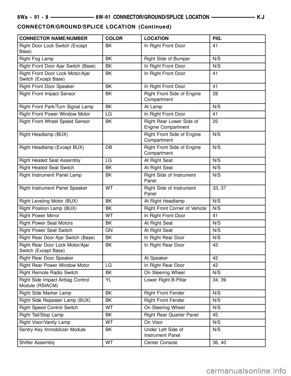
CONNECTOR NAME/NUMBER COLOR LOCATION FIG.
Right Door Lock Switch (Except
Base)BK In Right Front Door 41
Right Fog Lamp BK Right Side of Bumper N/S
Right Front Door Ajar Switch (Base) BK In Right Front Door N/S
Right Front Door Lock Motor/Ajar
Switch (Except Base)BK In Right Front Door 41
Right Front Door Speaker BK In Right Front Door 41
Right Front Impact Sensor BK Right Front Side of Engine
Compartment28
Right Front Park/Turn Signal Lamp BK At Lamp N/S
Right Front Power Window Motor LG In Right Front Door 41
Right Front Wheel Speed Sensor BK Right Rear Lower Side of
Engine Compartment25
Right Headlamp (BUX) Right Front Side of Engine
CompartmentN/S
Right Headlamp (Except BUX) DB Right Front Side of Engine
CompartmentN/S
Right Heated Seat Assembly LG At Right Seat N/S
Right Heated Seat Switch BK At Right Seat N/S
Right Instrument Panel Lamp BK Right Side of Instrument
PanelN/S
Right Instrument Panel Speaker WT Right Side of Instrument
Panel33, 37
Right Leveling Motor (BUX) BK At Right Headlamp N/S
Right Position Lamp (BUX) BK Right Front Corner of Vehicle N/S
Right Power Mirror WT In Right Front Door 41
Right Power Seat Motors BK At Right Seat N/S
Right Power Seat Switch GN At Right Seat N/S
Right Rear Door Ajar Switch (Base) BK In Right Rear Door N/S
Right Rear Door Lock Motor/Ajar
Switch (Except Base)BK In Right Rear Door 42
Right Rear Door Speaker At Speaker 42
Right Rear Power Window Motor LG In Right Rear Door 42
Right Remote Radio Switch BK On Steering Wheel N/S
Right Side Impact Airbag Control
Module (RSIACM)YL Lower Right B-Pillar 34, 39
Right Side Marker Lamp BK Right Front Fender N/S
Right Side Repeater Lamp (BUX) BK Right Front Fender N/S
Right Speed Control Switch WT On Steering Wheel N/S
Right Tail/Stop Lamp BK Right Rear Quarter Panel 45
Right Visor/Vanity Lamp WT On Visor N/S
Sentry Key Immobilizer Module BK Under Left Side of
Instrument PanelN/S
Shifter Assembly WT Center Console 36, 40
8Wa - 91 - 8 8W-91 CONNECTOR/GROUND/SPLICE LOCATIONKJ
CONNECTOR/GROUND/SPLICE LOCATION (Continued)
Page 1164 of 1803
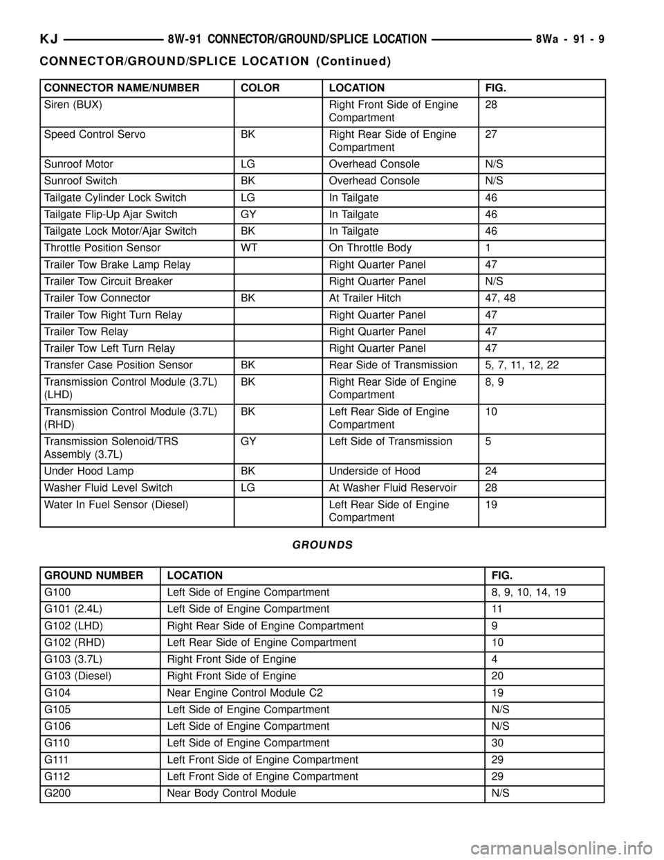
CONNECTOR NAME/NUMBER COLOR LOCATION FIG.
Siren (BUX) Right Front Side of Engine
Compartment28
Speed Control Servo BK Right Rear Side of Engine
Compartment27
Sunroof Motor LG Overhead Console N/S
Sunroof Switch BK Overhead Console N/S
Tailgate Cylinder Lock Switch LG In Tailgate 46
Tailgate Flip-Up Ajar Switch GY In Tailgate 46
Tailgate Lock Motor/Ajar Switch BK In Tailgate 46
Throttle Position Sensor WT On Throttle Body 1
Trailer Tow Brake Lamp Relay Right Quarter Panel 47
Trailer Tow Circuit Breaker Right Quarter Panel N/S
Trailer Tow Connector BK At Trailer Hitch 47, 48
Trailer Tow Right Turn Relay Right Quarter Panel 47
Trailer Tow Relay Right Quarter Panel 47
Trailer Tow Left Turn Relay Right Quarter Panel 47
Transfer Case Position Sensor BK Rear Side of Transmission 5, 7, 11, 12, 22
Transmission Control Module (3.7L)
(LHD)BK Right Rear Side of Engine
Compartment8, 9
Transmission Control Module (3.7L)
(RHD)BK Left Rear Side of Engine
Compartment10
Transmission Solenoid/TRS
Assembly (3.7L)GY Left Side of Transmission 5
Under Hood Lamp BK Underside of Hood 24
Washer Fluid Level Switch LG At Washer Fluid Reservoir 28
Water In Fuel Sensor (Diesel) Left Rear Side of Engine
Compartment19
GROUNDS
GROUND NUMBER LOCATION FIG.
G100 Left Side of Engine Compartment 8, 9, 10, 14, 19
G101 (2.4L) Left Side of Engine Compartment 11
G102 (LHD) Right Rear Side of Engine Compartment 9
G102 (RHD) Left Rear Side of Engine Compartment 10
G103 (3.7L) Right Front Side of Engine 4
G103 (Diesel) Right Front Side of Engine 20
G104 Near Engine Control Module C2 19
G105 Left Side of Engine Compartment N/S
G106 Left Side of Engine Compartment N/S
G110 Left Side of Engine Compartment 30
G111 Left Front Side of Engine Compartment 29
G112 Left Front Side of Engine Compartment 29
G200 Near Body Control Module N/S
KJ8W-91 CONNECTOR/GROUND/SPLICE LOCATION8Wa-91-9
CONNECTOR/GROUND/SPLICE LOCATION (Continued)
Page 1166 of 1803
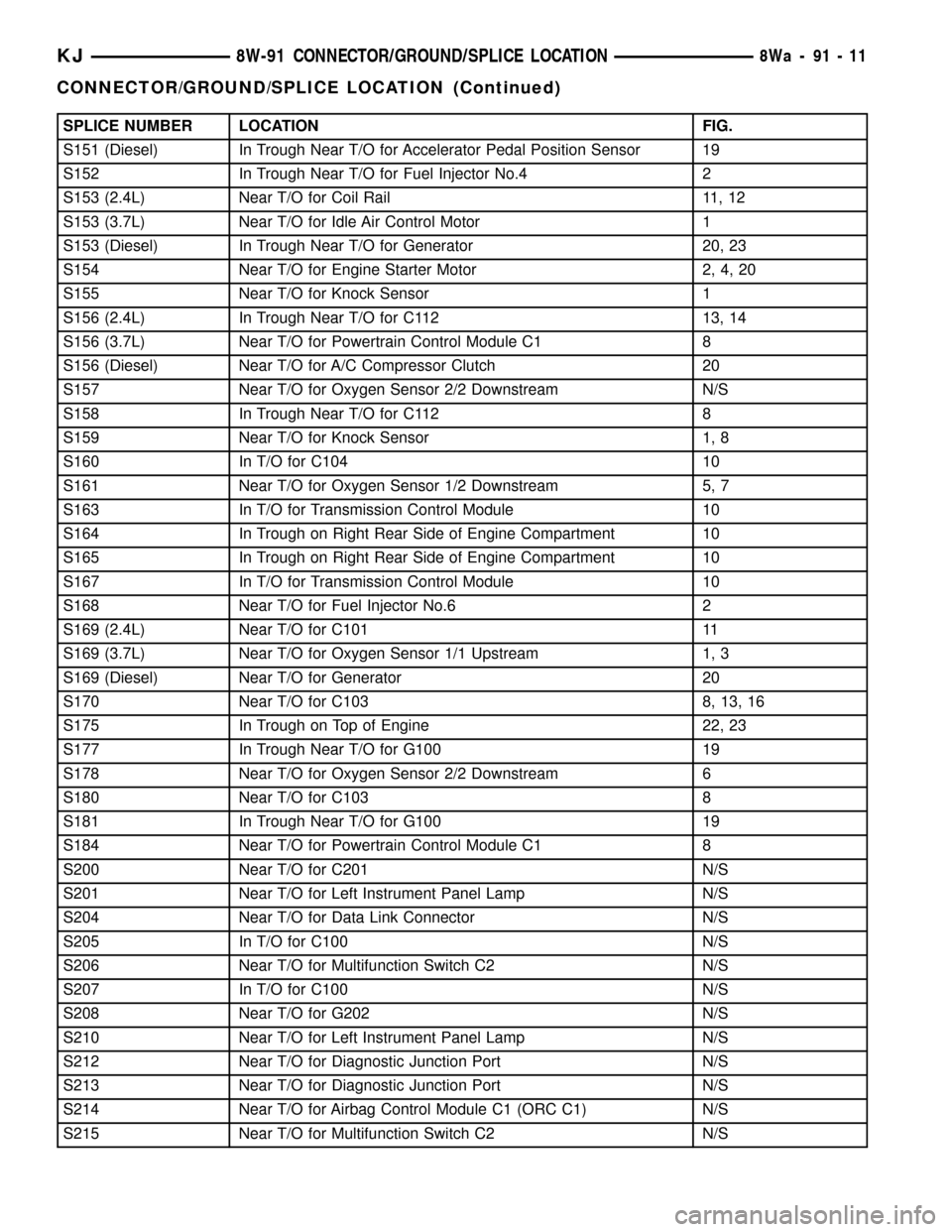
SPLICE NUMBER LOCATION FIG.
S151 (Diesel) In Trough Near T/O for Accelerator Pedal Position Sensor 19
S152 In Trough Near T/O for Fuel Injector No.4 2
S153 (2.4L) Near T/O for Coil Rail 11, 12
S153 (3.7L) Near T/O for Idle Air Control Motor 1
S153 (Diesel) In Trough Near T/O for Generator 20, 23
S154 Near T/O for Engine Starter Motor 2, 4, 20
S155 Near T/O for Knock Sensor 1
S156 (2.4L) In Trough Near T/O for C112 13, 14
S156 (3.7L) Near T/O for Powertrain Control Module C1 8
S156 (Diesel) Near T/O for A/C Compressor Clutch 20
S157 Near T/O for Oxygen Sensor 2/2 Downstream N/S
S158 In Trough Near T/O for C112 8
S159 Near T/O for Knock Sensor 1, 8
S160 In T/O for C104 10
S161 Near T/O for Oxygen Sensor 1/2 Downstream 5, 7
S163 In T/O for Transmission Control Module 10
S164 In Trough on Right Rear Side of Engine Compartment 10
S165 In Trough on Right Rear Side of Engine Compartment 10
S167 In T/O for Transmission Control Module 10
S168 Near T/O for Fuel Injector No.6 2
S169 (2.4L) Near T/O for C101 11
S169 (3.7L) Near T/O for Oxygen Sensor 1/1 Upstream 1, 3
S169 (Diesel) Near T/O for Generator 20
S170 Near T/O for C103 8, 13, 16
S175 In Trough on Top of Engine 22, 23
S177 In Trough Near T/O for G100 19
S178 Near T/O for Oxygen Sensor 2/2 Downstream 6
S180 Near T/O for C103 8
S181 In Trough Near T/O for G100 19
S184 Near T/O for Powertrain Control Module C1 8
S200 Near T/O for C201 N/S
S201 Near T/O for Left Instrument Panel Lamp N/S
S204 Near T/O for Data Link Connector N/S
S205 In T/O for C100 N/S
S206 Near T/O for Multifunction Switch C2 N/S
S207 In T/O for C100 N/S
S208 Near T/O for G202 N/S
S210 Near T/O for Left Instrument Panel Lamp N/S
S212 Near T/O for Diagnostic Junction Port N/S
S213 Near T/O for Diagnostic Junction Port N/S
S214 Near T/O for Airbag Control Module C1 (ORC C1) N/S
S215 Near T/O for Multifunction Switch C2 N/S
KJ8W-91 CONNECTOR/GROUND/SPLICE LOCATION8Wa-91-11
CONNECTOR/GROUND/SPLICE LOCATION (Continued)
Page 1168 of 1803
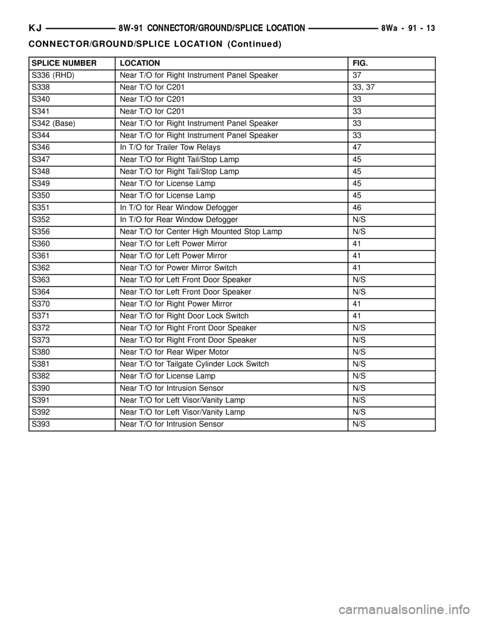
SPLICE NUMBER LOCATION FIG.
S336 (RHD) Near T/O for Right Instrument Panel Speaker 37
S338 Near T/O for C201 33, 37
S340 Near T/O for C201 33
S341 Near T/O for C201 33
S342 (Base) Near T/O for Right Instrument Panel Speaker 33
S344 Near T/O for Right Instrument Panel Speaker 33
S346 In T/O for Trailer Tow Relays 47
S347 Near T/O for Right Tail/Stop Lamp 45
S348 Near T/O for Right Tail/Stop Lamp 45
S349 Near T/O for License Lamp 45
S350 Near T/O for License Lamp 45
S351 In T/O for Rear Window Defogger 46
S352 In T/O for Rear Window Defogger N/S
S356 Near T/O for Center High Mounted Stop Lamp N/S
S360 Near T/O for Left Power Mirror 41
S361 Near T/O for Left Power Mirror 41
S362 Near T/O for Power Mirror Switch 41
S363 Near T/O for Left Front Door Speaker N/S
S364 Near T/O for Left Front Door Speaker N/S
S370 Near T/O for Right Power Mirror 41
S371 Near T/O for Right Door Lock Switch 41
S372 Near T/O for Right Front Door Speaker N/S
S373 Near T/O for Right Front Door Speaker N/S
S380 Near T/O for Rear Wiper Motor N/S
S381 Near T/O for Tailgate Cylinder Lock Switch N/S
S382 Near T/O for License Lamp N/S
S390 Near T/O for Intrusion Sensor N/S
S391 Near T/O for Left Visor/Vanity Lamp N/S
S392 Near T/O for Left Visor/Vanity Lamp N/S
S393 Near T/O for Intrusion Sensor N/S
KJ8W-91 CONNECTOR/GROUND/SPLICE LOCATION8Wa-91-13
CONNECTOR/GROUND/SPLICE LOCATION (Continued)
Page 1217 of 1803
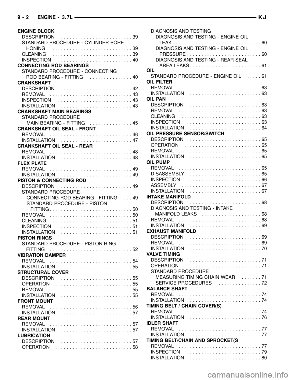
ENGINE BLOCK
DESCRIPTION.........................39
STANDARD PROCEDURE - CYLINDER BORE
HONING............................39
CLEANING............................39
INSPECTION..........................40
CONNECTING ROD BEARINGS
STANDARD PROCEDURE - CONNECTING
ROD BEARING - FITTING...............40
CRANKSHAFT
DESCRIPTION.........................42
REMOVAL.............................43
INSPECTION..........................43
INSTALLATION.........................43
CRANKSHAFT MAIN BEARINGS
STANDARD PROCEDURE
MAIN BEARING - FITTING...............45
CRANKSHAFT OIL SEAL - FRONT
REMOVAL.............................46
INSTALLATION.........................47
CRANKSHAFT OIL SEAL - REAR
REMOVAL.............................48
INSTALLATION.........................48
FLEX PLATE
REMOVAL.............................49
INSTALLATION.........................49
PISTON & CONNECTING ROD
DESCRIPTION.........................49
STANDARD PROCEDURE
CONNECTING ROD BEARING - FITTING . . . 49
STANDARD PROCEDURE - PISTON
FITTING.............................50
REMOVAL.............................50
CLEANING............................51
INSPECTION..........................51
INSTALLATION.........................51
PISTON RINGS
STANDARD PROCEDURE - PISTON RING
FITTING.............................52
VIBRATION DAMPER
REMOVAL.............................54
INSTALLATION.........................55
STRUCTURAL COVER
DESCRIPTION.........................55
OPERATION...........................55
REMOVAL.............................55
INSTALLATION.........................55
FRONT MOUNT
REMOVAL.............................56
INSTALLATION.........................57
REAR MOUNT
REMOVAL.............................57
INSTALLATION.........................57
LUBRICATION
DESCRIPTION.........................57
OPERATION...........................58DIAGNOSIS AND TESTING
DIAGNOSIS AND TESTING - ENGINE OIL
LEAK...............................60
DIAGNOSIS AND TESTING - ENGINE OIL
PRESSURE..........................60
DIAGNOSIS AND TESTING - REAR SEAL
AREA LEAKS.........................61
OIL
STANDARD PROCEDURE - ENGINE OIL.....61
OIL FILTER
REMOVAL.............................63
INSTALLATION.........................63
OIL PAN
DESCRIPTION.........................63
REMOVAL.............................63
CLEANING............................63
INSPECTION..........................63
INSTALLATION.........................64
OIL PRESSURE SENSOR/SWITCH
DESCRIPTION.........................65
OPERATION...........................65
REMOVAL.............................65
INSTALLATION.........................65
OIL PUMP
REMOVAL.............................65
DISASSEMBLY.........................65
INSPECTION..........................66
ASSEMBLY............................67
INSTALLATION.........................67
INTAKE MANIFOLD
DESCRIPTION.........................68
DIAGNOSIS AND TESTING - INTAKE
MANIFOLD LEAKS.....................68
REMOVAL.............................68
INSTALLATION.........................69
EXHAUST MANIFOLD
DESCRIPTION.........................69
REMOVAL.............................69
INSTALLATION.........................70
VALVE TIMING
DESCRIPTION.........................71
OPERATION...........................71
STANDARD PROCEDURE
MEASURING TIMING CHAIN WEAR.......71
SERVICE PROCEDURES...............72
BALANCE SHAFT
REMOVAL.............................74
INSTALLATION.........................74
TIMING BELT / CHAIN COVER(S)
REMOVAL.............................74
INSTALLATION.........................76
IDLER SHAFT
REMOVAL.............................77
INSTALLATION.........................77
TIMING BELT/CHAIN AND SPROCKET(S
REMOVAL.............................77
INSPECTION..........................79
INSTALLATION.........................80
9 - 2 ENGINE - 3.7LKJ
Page 1219 of 1803
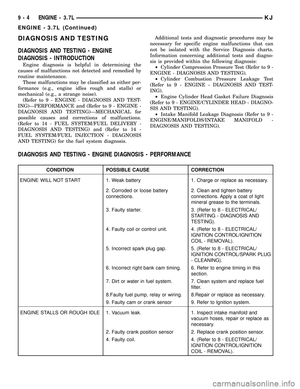
DIAGNOSIS AND TESTING
DIAGNOSIS AND TESTING - ENGINE
DIAGNOSIS - INTRODUCTION
Engine diagnosis is helpful in determining the
causes of malfunctions not detected and remedied by
routine maintenance.
These malfunctions may be classified as either per-
formance (e.g., engine idles rough and stalls) or
mechanical (e.g., a strange noise).
(Refer to 9 - ENGINE - DIAGNOSIS AND TEST-
ING)ÐPERFORMANCE and (Refer to 9 - ENGINE -
DIAGNOSIS AND TESTING)ÐMECHANICAL for
possible causes and corrections of malfunctions.
(Refer to 14 - FUEL SYSTEM/FUEL DELIVERY -
DIAGNOSIS AND TESTING) and (Refer to 14 -
FUEL SYSTEM/FUEL INJECTION - DIAGNOSIS
AND TESTING) for the fuel system diagnosis.Additional tests and diagnostic procedures may be
necessary for specific engine malfunctions that can
not be isolated with the Service Diagnosis charts.
Information concerning additional tests and diagno-
sis is provided within the following diagnosis:
²Cylinder Compression Pressure Test (Refer to 9 -
ENGINE - DIAGNOSIS AND TESTING).
²Cylinder Combustion Pressure Leakage Test
(Refer to 9 - ENGINE - DIAGNOSIS AND TEST-
ING).
²Engine Cylinder Head Gasket Failure Diagnosis
(Refer to 9 - ENGINE/CYLINDER HEAD - DIAGNO-
SIS AND TESTING).
²Intake Manifold Leakage Diagnosis (Refer to 9 -
ENGINE/MANIFOLDS/INTAKE MANIFOLD -
DIAGNOSIS AND TESTING).
DIAGNOSIS AND TESTING - ENGINE DIAGNOSIS - PERFORMANCE
CONDITION POSSIBLE CAUSE CORRECTION
ENGINE WILL NOT START 1. Weak battery 1. Charge or replace as necessary.
2. Corroded or loose battery
connections.2. Clean and tighten battery
connections. Apply a coat of light
mineral grease to the terminals.
3. Faulty starter. 3. (Refer to 8 - ELECTRICAL/
STARTING - DIAGNOSIS AND
TESTING).
4. Faulty coil or control unit. 4. (Refer to 8 - ELECTRICAL/
IGNITION CONTROL/IGNITION
COIL - REMOVAL).
5. Incorrect spark plug gap. 5. (Refer to 8 - ELECTRICAL/
IGNITION CONTROL/SPARK PLUG
- CLEANING).
6. Incorrect right bank cam timing. 6. Refer to engine timing in this
section.
7. Dirt or water in fuel system. 7. Clean system and replace fuel
filter.
8.Faulty fuel pump, relay or wiring. 8.Repair or replace as necessary.
9. Faulty cam or crank sensor 9. Refer to Ignition system.
ENGINE STALLS OR ROUGH IDLE 1. Vacuum leak. 1. Inspect intake manifold and
vacuum hoses, repair or replace as
necessary.
2. Faulty crank position sensor 2. Replace crank position sensor.
4. Faulty coil. 4. (Refer to 8 - ELECTRICAL/
IGNITION CONTROL/IGNITION
COIL - REMOVAL).
9 - 4 ENGINE - 3.7LKJ
ENGINE - 3.7L (Continued)
Page 1222 of 1803
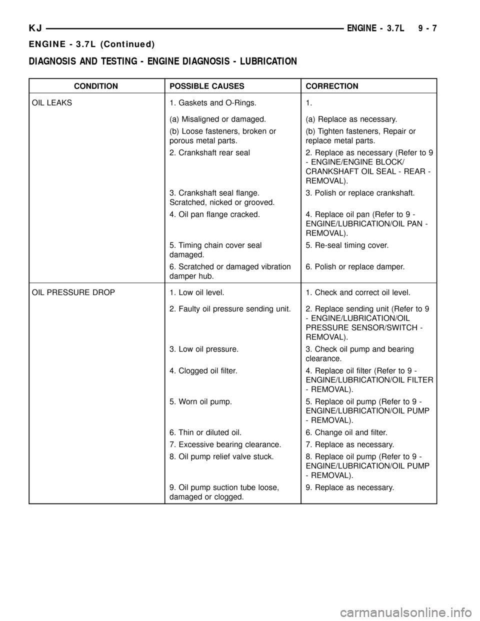
DIAGNOSIS AND TESTING - ENGINE DIAGNOSIS - LUBRICATION
CONDITION POSSIBLE CAUSES CORRECTION
OIL LEAKS 1. Gaskets and O-Rings. 1.
(a) Misaligned or damaged. (a) Replace as necessary.
(b) Loose fasteners, broken or
porous metal parts.(b) Tighten fasteners, Repair or
replace metal parts.
2. Crankshaft rear seal 2. Replace as necessary (Refer to 9
- ENGINE/ENGINE BLOCK/
CRANKSHAFT OIL SEAL - REAR -
REMOVAL).
3. Crankshaft seal flange.
Scratched, nicked or grooved.3. Polish or replace crankshaft.
4. Oil pan flange cracked. 4. Replace oil pan (Refer to 9 -
ENGINE/LUBRICATION/OIL PAN -
REMOVAL).
5. Timing chain cover seal
damaged.5. Re-seal timing cover.
6. Scratched or damaged vibration
damper hub.6. Polish or replace damper.
OIL PRESSURE DROP 1. Low oil level. 1. Check and correct oil level.
2. Faulty oil pressure sending unit. 2. Replace sending unit (Refer to 9
- ENGINE/LUBRICATION/OIL
PRESSURE SENSOR/SWITCH -
REMOVAL).
3. Low oil pressure. 3. Check oil pump and bearing
clearance.
4. Clogged oil filter. 4. Replace oil filter (Refer to 9 -
ENGINE/LUBRICATION/OIL FILTER
- REMOVAL).
5. Worn oil pump. 5. Replace oil pump (Refer to 9 -
ENGINE/LUBRICATION/OIL PUMP
- REMOVAL).
6. Thin or diluted oil. 6. Change oil and filter.
7. Excessive bearing clearance. 7. Replace as necessary.
8. Oil pump relief valve stuck. 8. Replace oil pump (Refer to 9 -
ENGINE/LUBRICATION/OIL PUMP
- REMOVAL).
9. Oil pump suction tube loose,
damaged or clogged.9. Replace as necessary.
KJENGINE - 3.7L 9 - 7
ENGINE - 3.7L (Continued)
Page 1225 of 1803
²Tapping the hole with a special Heli-Coil Tap, or
equivalent.
²Installing an insert into the tapped hole to bring
the hole back to its original thread size.
STANDARD PROCEDURE - ENGINE CORE AND
OIL GALLERY PLUGS
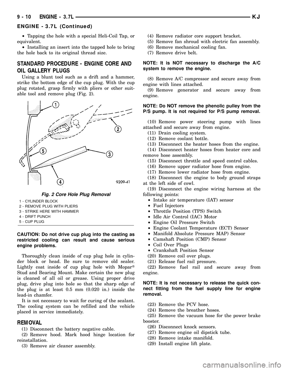
Using a blunt tool such as a drift and a hammer,
strike the bottom edge of the cup plug. With the cup
plug rotated, grasp firmly with pliers or other suit-
able tool and remove plug (Fig. 2).
CAUTION: Do not drive cup plug into the casting as
restricted cooling can result and cause serious
engine problems.
Thoroughly clean inside of cup plug hole in cylin-
der block or head. Be sure to remove old sealer.
Lightly coat inside of cup plug hole with Mopart
Stud and Bearing Mount. Make certain the new plug
is cleaned of all oil or grease. Using proper drive
plug, drive plug into hole so that the sharp edge of
the plug is at least 0.5 mm (0.020 in.) inside the
lead-in chamfer.
It is not necessary to wait for curing of the sealant.
The cooling system can be refilled and the vehicle
placed in service immediately.
REMOVAL
(1) Disconnect the battery negative cable.
(2) Remove hood. Mark hood hinge location for
reinstallation.
(3) Remove air cleaner assembly.(4) Remove radiator core support bracket.
(5) Remove fan shroud with electric fan assembly.
(6) Remove mechanical cooling fan.
(7) Remove drive belt.
NOTE: It is NOT necessary to discharge the A/C
system to remove the engine.
(8) Remove A/C compressor and secure away from
engine with lines attached.
(9) Remove generator and secure away from
engine.
NOTE: Do NOT remove the phenolic pulley from the
P/S pump. It is not required for P/S pump removal.
(10) Remove power steering pump with lines
attached and secure away from engine.
(11) Drain cooling system.
(12) Remove coolant bottle.
(13) Disconnect the heater hoses from the engine.
(14) Disconnect heater hoses from heater core and
remove hose assembly.
(15) Disconnect throttle and speed control cables.
(16) Remove upper radiator hose from engine.
(17) Remove lower radiator hose from engine.
(18) Disconnect the engine to body ground straps
at the left side of cowl.
(19) Disconnect the engine wiring harness at the
following points:
²Intake air temperature (IAT) sensor
²Fuel Injectors
²Throttle Position (TPS) Switch
²Idle Air Control (IAC) Motor
²Engine Oil Pressure Switch
²Engine Coolant Temperature (ECT) Sensor
²Manifold Absolute Pressure MAP) Sensor
²Camshaft Position (CMP) Sensor
²Coil Over Plugs
²Crankshaft Position Sensor
(20) Remove coil over plugs.
(21) Release fuel rail pressure.
(22) Remove fuel rail and secure away from
engine.
NOTE: It is not necessary to release the quick con-
nect fitting from the fuel supply line for engine
removal.
(23) Remove the PCV hose.
(24) Remove the breather hoses.
(25) Remove the vacuum hose for the power brake
booster.
(26) Disconnect knock sensors.
(27) Remove engine oil dipstick tube.
(28) Remove intake manifold.
(29) Install engine lift plate.
Fig. 2 Core Hole Plug Removal
1 - CYLINDER BLOCK
2 - REMOVE PLUG WITH PLIERS
3 - STRIKE HERE WITH HAMMER
4 - DRIFT PUNCH
5 - CUP PLUG
9 - 10 ENGINE - 3.7LKJ
ENGINE - 3.7L (Continued)
Page 1226 of 1803
NOTE: Recheck bolt torque for engine lift plate
before removing engine.
(30) Secure the left and right engine wiring har-
nesses away from engine.
(31) Raise vehicle.
(32) Disconnect oxygen sensor wiring.
(33) Disconnect crankshaft postion sensor.
(34) Disconnect the engine block heater power
cable, if equipped.
(35) Disconnect the front propshaft at the front
differential and secure out of way.
NOTE: It is necessary to disconnect the front prop-
shaft for access to the starter and left side exhaust
flange.
(36) Remove the starter.
(37) Remove the ground straps from the left and
right side of the block.
(38) Disconnect the right and left exhaust pipes at
the manifolds and from the crossover, and remove
from the vehicle.
NOTE: The exhaust clamps at the manifolds cannot
be reused. New clamps must be used or leaks may
occur.
NOTE: For manual transmission vehicles, the trans-
mission must be removed from the vehicle, before
the engine can be removed. The manual transmis-
sion will contact the floorpan before the engine
clears the motor mounts, so it must be removed.
(39) Remove the structural cover.
(40) Remove torque convertor bolts, and mark
location for reassembly.
(41) Remove transmission bellhousing to engine
bolts.
(42) Loosen left and right engine mount thru bolts.
NOTE: It is not necessary to completely remove
engine mount thru bolts, for engine removal.
(43) Lower the vehicle.
(44) Support the transmission with a suitable jack.
(45) Connect a suitable engine hoist to the engine
lift plate.
(46) Remove engine from vehicle.
INSTALLATION
(1) Position the engine in the vehicle.
(2) Install both left and right side engine mounts
onto engine.
(3) Raise the vehicle.(4) Install the transmission bellhousing to engine
mounting bolts. Tighten the bolts to 41 N´m (30ft.
lbs.).
(5) Tighten the engine mount thru bolts.
(6) Install the torque convertor bolts.
(7) Connect the ground straps on the left and right
side of the engine.
(8) Install the starter.
(9) Connect the crankshaft position sensor.
(10) Install the engine block heater power cable, if
equipped.
CAUTION: The structural cover requires a specific
torque sequence. Failure to follow this sequence
may cause severe damage to the cover.
(11) Install the structural cover.
NOTE: New clamps must be used on exhaust man-
ifold flanges. Failure to use new clamps may result
in exhaust leaks.
(12) Install the left and right exhaust pipes.
(13) Connect the left and right oxygen sensors.
(14) Lower vehicle.
(15) Remove the engine lift plate.
(16) Connect the knock sensors.
(17) Connect the engine to body ground straps at
the left side of the cowl.
(18) Install the intake manifold.
(19) Install the engine oil dipstick tube.
(20) Install the power brake booster vacuum hose.
(21) Install the breather hoses.
(22) Install the PCV hose.
(23) Install the fuel rail.
(24) Install the coil over plugs.
(25) Connect the engine wiring harness at the fol-
lowing points:
²Intake air temperature (IAT) sensor
²Fuel Injectors
²Throttle Position (TPS) Switch
²Idle Air Control (IAC) Motor
²Engine Oil Pressure Switch
²Engine Coolant Temperature (ECT) Sensor
²Manifold Absolute Pressure MAP) Sensor
²Camshaft Position (CMP) Sensor
²Coil Over Plugs
²Crankshaft Position Sensor
(26) Connect lower radiator hose.
(27) Connect upper radiator hose.
(28) Connect throttle and speed control cables.
(29) Install the heater hose assembly.
(30) Install coolant recovery bottle.
(31) Install the power steering pump.
(32) Install the generator.
(33) Install the A/C compressor.
(34) Install the drive belt.
KJENGINE - 3.7L 9 - 11
ENGINE - 3.7L (Continued)