Front oil seal JEEP LIBERTY 2002 KJ / 1.G Owner's Manual
[x] Cancel search | Manufacturer: JEEP, Model Year: 2002, Model line: LIBERTY, Model: JEEP LIBERTY 2002 KJ / 1.GPages: 1803, PDF Size: 62.3 MB
Page 1262 of 1803
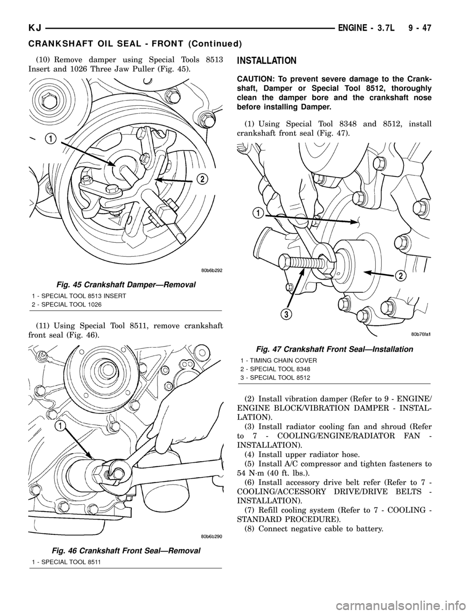
(10) Remove damper using Special Tools 8513
Insert and 1026 Three Jaw Puller (Fig. 45).
(11) Using Special Tool 8511, remove crankshaft
front seal (Fig. 46).INSTALLATION
CAUTION: To prevent severe damage to the Crank-
shaft, Damper or Special Tool 8512, thoroughly
clean the damper bore and the crankshaft nose
before installing Damper.
(1) Using Special Tool 8348 and 8512, install
crankshaft front seal (Fig. 47).
(2) Install vibration damper (Refer to 9 - ENGINE/
ENGINE BLOCK/VIBRATION DAMPER - INSTAL-
LATION).
(3) Install radiator cooling fan and shroud (Refer
to 7 - COOLING/ENGINE/RADIATOR FAN -
INSTALLATION).
(4) Install upper radiator hose.
(5) Install A/C compressor and tighten fasteners to
54 N´m (40 ft. lbs.).
(6) Install accessory drive belt refer (Refer to 7 -
COOLING/ACCESSORY DRIVE/DRIVE BELTS -
INSTALLATION).
(7) Refill cooling system (Refer to 7 - COOLING -
STANDARD PROCEDURE).
(8) Connect negative cable to battery.
Fig. 45 Crankshaft DamperÐRemoval
1 - SPECIAL TOOL 8513 INSERT
2 - SPECIAL TOOL 1026
Fig. 46 Crankshaft Front SealÐRemoval
1 - SPECIAL TOOL 8511
Fig. 47 Crankshaft Front SealÐInstallation
1 - TIMING CHAIN COVER
2 - SPECIAL TOOL 8348
3 - SPECIAL TOOL 8512
KJENGINE - 3.7L 9 - 47
CRANKSHAFT OIL SEAL - FRONT (Continued)
Page 1284 of 1803
(11) Bleed fuel system. Refer to FUEL SYSTEM.
(12) Remove fuel rail.
(13) Remove throttle body assembly and mounting
bracket.
(14) Drain cooling system below coolant tempera-
ture level. Refer to COOLING SYSTEM.
(15) Remove the heater hoses from the engine
front cover and the heater core.
(16) Unclip and remove heater hoses and tubes
from intake manifold.
(17) Remove coolant temperature sensor. Refer to
FUEL SYSTEM.
(18) Remove intake manifold retaining fasteners in
reverse order of tightening sequence.
(19) Remove intake manifold.
INSTALLATION
(1) Install intake manifold gaskets.
(2) Install intake manifold.
(3) Install intake manifold retaining bolts and
tighten in sequence shown in to 12 N´m (105 in. lbs.).
(4) Install left and right radio suppressor straps.
(5) Install throttle body assembly.
(6) Install throttle cable bracket.
(7) Connect throttle cable and speed control cable
to throttle body.
(8) Install fuel rail.
(9) Install ignition coil towers.
(10) Position and install heater hoses and tubes
onto intake manifold.
(11) Install the heater hoses to the heater core and
engine front cover.
(12) Connect electrical connectors for the following
components:
²Manifold Absolute Pressure (MAP) Sensor
²Intake Air Temperature (IAT) Sensor
²Throttle Position (TPS) Sensor
²Coolant Temperature (CTS) Sensor
²Idle Air Control (IAC) Motor
²Ignition coil towers
²Fuel injectors
(13) Install top oil dipstick tube retaining bolt and
ground strap.
(14) Connect generator electrical connections.
(15) Connect Vapor purge hose, Brake booster
hose, Speed control servo hose, Positive crankcase
ventilation (PCV) hose.
(16) Fill cooling system.
(17) Install resonator assembly and air inlet hose.
(18) Connect negative cable to battery.
EXHAUST MANIFOLD
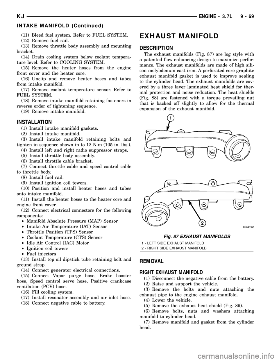
DESCRIPTION
The exhaust manifolds (Fig. 87) are log style with
a patented flow enhancing design to maximize perfor-
mance. The exhaust manifolds are made of high sili-
con molybdenum cast iron. A perforated core graphite
exhaust manifold gasket is used to improve sealing
to the cylinder head. The exhaust manifolds are cov-
ered by a three layer laminated heat shield for ther-
mal protection and noise reduction. The heat shields
(Fig. 88) are fastened with a torque prevailing nut
that is backed off slightly to allow for the thermal
expansion of the exhaust manifold.
REMOVAL
RIGHT EXHAUST MANIFOLD
(1) Disconnect the negative cable from the battery.
(2) Raise and support the vehicle.
(3) Remove the bolts and nuts attaching the
exhaust pipe to the engine exhaust manifold.
(4) Lower the vehicle.
(5) Remove the exhaust heat shield (Fig. 89).
(6) Remove bolts, nuts and washers attaching
manifold to cylinder head.
(7) Remove manifold and gasket from the cylinder
head.
Fig. 87 EXHAUST MANIFOLDS
1 - LEFT SIDE EXHAUST MANIFOLD
2 - RIGHT SIDE EXHAUST MANIFOLD
KJENGINE - 3.7L 9 - 69
INTAKE MANIFOLD (Continued)
Page 1291 of 1803
INSTALLATION
CAUTION: Do not use oil based liquids to clean tim-
ing cover or block surfaces. Use only rubbing alco-
hol, along with plastic or wooden scrapers. Use no
wire brushes or abrasive wheels or metal scrapers,
or damage to surfaces could result.
(1) Clean timing chain cover and block surface
using rubbing alcohol.
CAUTION: The 3.7L uses a special anerobic sealer
instead of a gasket to seal the timing cover to the
engine block, from the factory. For service repairs,
MoparTEngine RTV must be used as a substitute.
(2) Inspect the water passage o-rings for any dam-
age, and replace as necessary.
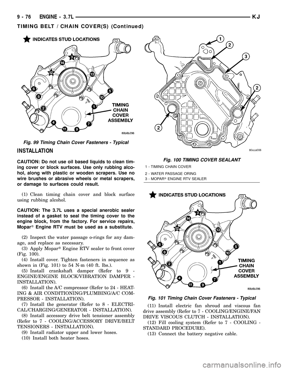
(3) Apply MopartEngine RTV sealer to front cover
(Fig. 100).
(4) Install cover. Tighten fasteners in sequence as
shown in (Fig. 101) to 54 N´m (40 ft. lbs.).
(5) Install crankshaft damper (Refer to 9 -
ENGINE/ENGINE BLOCK/VIBRATION DAMPER -
INSTALLATION).
(6) Install the A/C compressor (Refer to 24 - HEAT-
ING & AIR CONDITIONING/PLUMBING/A/C COM-
PRESSOR - INSTALLATION).
(7) Install the generator (Refer to 8 - ELECTRI-
CAL/CHARGING/GENERATOR - INSTALLATION).
(8) Install accessory drive belt tensioner assembly
(Refer to 7 - COOLING/ACCESSORY DRIVE/BELT
TENSIONERS - INSTALLATION).
(9) Install radiator upper and lower hoses.
(10) Install both heater hoses.(11) Install electric fan shroud and viscous fan
drive assembly (Refer to 7 - COOLING/ENGINE/FAN
DRIVE VISCOUS CLUTCH - INSTALLATION).
(12) Fill cooling system (Refer to 7 - COOLING -
STANDARD PROCEDURE).
(13) Connect the battery negative cable.
Fig. 99 Timing Chain Cover Fasteners - Typical
Fig. 100 TIMING COVER SEALANT
1 - TIMING CHAIN COVER
2 - WATER PASSAGE ORING
3 - MOPARTENGINE RTV SEALER
Fig. 101 Timing Chain Cover Fasteners - Typical
9 - 76 ENGINE - 3.7LKJ
TIMING BELT / CHAIN COVER(S) (Continued)
Page 1295 of 1803
INSTALLATION
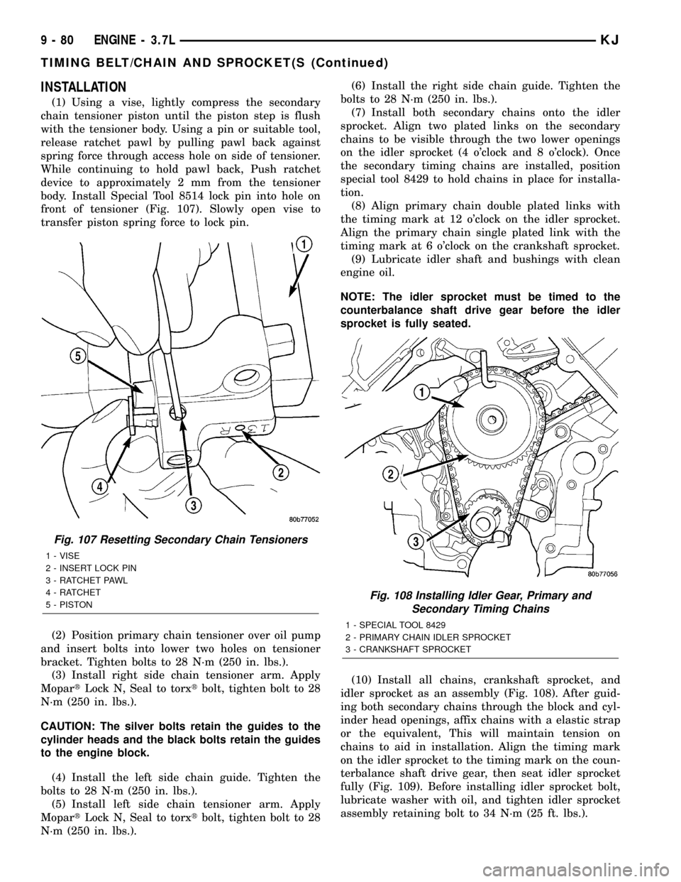
(1) Using a vise, lightly compress the secondary
chain tensioner piston until the piston step is flush
with the tensioner body. Using a pin or suitable tool,
release ratchet pawl by pulling pawl back against
spring force through access hole on side of tensioner.
While continuing to hold pawl back, Push ratchet
device to approximately 2 mm from the tensioner
body. Install Special Tool 8514 lock pin into hole on
front of tensioner (Fig. 107). Slowly open vise to
transfer piston spring force to lock pin.
(2) Position primary chain tensioner over oil pump
and insert bolts into lower two holes on tensioner
bracket. Tighten bolts to 28 N´m (250 in. lbs.).
(3) Install right side chain tensioner arm. Apply
MopartLock N, Seal to torxtbolt, tighten bolt to 28
N´m (250 in. lbs.).
CAUTION: The silver bolts retain the guides to the
cylinder heads and the black bolts retain the guides
to the engine block.
(4) Install the left side chain guide. Tighten the
bolts to 28 N´m (250 in. lbs.).
(5) Install left side chain tensioner arm. Apply
MopartLock N, Seal to torxtbolt, tighten bolt to 28
N´m (250 in. lbs.).(6) Install the right side chain guide. Tighten the
bolts to 28 N´m (250 in. lbs.).
(7) Install both secondary chains onto the idler
sprocket. Align two plated links on the secondary
chains to be visible through the two lower openings
on the idler sprocket (4 o'clock and 8 o'clock). Once
the secondary timing chains are installed, position
special tool 8429 to hold chains in place for installa-
tion.
(8) Align primary chain double plated links with
the timing mark at 12 o'clock on the idler sprocket.
Align the primary chain single plated link with the
timing mark at 6 o'clock on the crankshaft sprocket.
(9) Lubricate idler shaft and bushings with clean
engine oil.
NOTE: The idler sprocket must be timed to the
counterbalance shaft drive gear before the idler
sprocket is fully seated.
(10) Install all chains, crankshaft sprocket, and
idler sprocket as an assembly (Fig. 108). After guid-
ing both secondary chains through the block and cyl-
inder head openings, affix chains with a elastic strap
or the equivalent, This will maintain tension on
chains to aid in installation. Align the timing mark
on the idler sprocket to the timing mark on the coun-
terbalance shaft drive gear, then seat idler sprocket
fully (Fig. 109). Before installing idler sprocket bolt,
lubricate washer with oil, and tighten idler sprocket
assembly retaining bolt to 34 N´m (25 ft. lbs.).
Fig. 107 Resetting Secondary Chain Tensioners
1 - VISE
2 - INSERT LOCK PIN
3 - RATCHET PAWL
4 - RATCHET
5 - PISTON
Fig. 108 Installing Idler Gear, Primary and
Secondary Timing Chains
1 - SPECIAL TOOL 8429
2 - PRIMARY CHAIN IDLER SPROCKET
3 - CRANKSHAFT SPROCKET
9 - 80 ENGINE - 3.7LKJ
TIMING BELT/CHAIN AND SPROCKET(S (Continued)
Page 1299 of 1803
CRANKSHAFT
DESCRIPTION.........................32
OPERATION...........................33
STANDARD PROCEDURE - CRANKSHAFT
ENDPLAY ...........................33
REMOVAL.............................33
INSPECTION..........................34
INSTALLATION.........................34
CRANKSHAFT MAIN BEARINGS
STANDARD PROCEDURE - MAIN BEARING -
FITTING.............................35
CRANKSHAFT OIL SEAL - FRONT
REMOVAL.............................37
INSTALLATION.........................37
CRANKSHAFT OIL SEAL - REAR
REMOVAL.............................38
INSTALLATION.........................39
PISTON & CONNECTING ROD
DESCRIPTION.........................40
OPERATION...........................40
REMOVAL.............................40
INSTALLATION.........................41
PISTON RINGS
STANDARD PROCEDURE
PISTON RING - FITTING................42
VIBRATION DAMPER
REMOVAL.............................43
INSTALLATION.........................43
STRUCTURAL COLLAR
REMOVAL.............................44
INSTALLATION.........................44
ENGINE MOUNTING
DESCRIPTION.........................44
FRONT MOUNT
REMOVAL.............................44
INSTALLATION.........................44
REAR MOUNT
REMOVAL.............................45
INSTALLATION.........................45
LUBRICATION
DESCRIPTION.........................46
OPERATION...........................46
DIAGNOSIS AND TESTING - ENGINE OIL
PRESSURE CHECKING.................46
OIL
STANDARD PROCEDURE
ENGINE OIL LEVEL CHECK.............47
STANDARD PROCEDURE - ENGINE OIL
AND FILTER CHANGE..................47
OIL FILTER
DESCRIPTION.........................47
REMOVAL.............................47
INSTALLATION.........................47
OIL PAN
REMOVAL.............................48INSTALLATION.........................48
OIL PRESSURE SENSOR/SWITCH
DESCRIPTION.........................48
OPERATION...........................48
OIL PUMP
REMOVAL.............................49
DISASSEMBLY.........................49
CLEANING............................49
INSPECTION..........................50
ASSEMBLY............................50
INSTALLATION.........................50
INTAKE MANIFOLD
DESCRIPTION.........................51
OPERATION...........................51
DIAGNOSIS AND TESTING - INTAKE
MANIFOLD LEAKS.....................51
REMOVAL.............................52
INSPECTION..........................52
INSTALLATION.........................52
EXHAUST MANIFOLD
DESCRIPTION.........................53
OPERATION...........................53
REMOVAL.............................53
CLEANING............................53
INSPECTION..........................53
INSTALLATION.........................53
TIMING BELT COVER(S)
REMOVAL.............................53
INSTALLATION.........................53
TIMING BELT AND SPROCKET(S)
REMOVAL
REMOVAL - TIMING BELT...............55
REMOVAL - CRANKSHAFT SPROCKET....55
CLEANING............................55
INSTALLATION
INSTALLATION - CRANKSHAFT SPROCKET . 56
INSTALLATION - TIMING BELT...........56
TIMING BELT TENSIONER & PULLEY
REMOVAL.............................59
INSTALLATION.........................59
BALANCE SHAFT
DESCRIPTION.........................59
OPERATION...........................59
REMOVAL.............................60
INSTALLATION
BALANCE SHAFT TIMING...............61
BALANCE SHAFT CARRIER
REMOVAL.............................64
INSTALLATION.........................64
BALANCE SHAFT CHAIN
REMOVAL.............................64
INSTALLATION.........................64
9s - 2 ENGINEKJ
Page 1314 of 1803
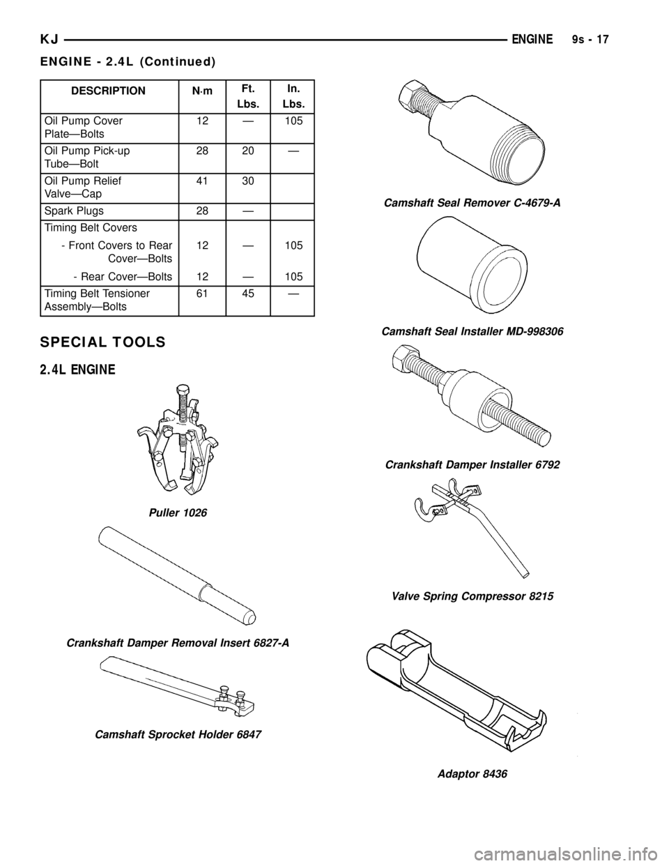
DESCRIPTION N´mFt.
Lbs.In.
Lbs.
Oil Pump Cover
PlateÐBolts12 Ð 105
Oil Pump Pick-up
TubeÐBolt28 20 Ð
Oil Pump Relief
ValveÐCap41 30
Spark Plugs 28 Ð
Timing Belt Covers
- Front Covers to Rear
CoverÐBolts12 Ð 105
- Rear CoverÐBolts 12 Ð 105
Timing Belt Tensioner
AssemblyÐBolts61 45 Ð
SPECIAL TOOLS
2.4L ENGINE
Puller 1026
Crankshaft Damper Removal Insert 6827-A
Camshaft Sprocket Holder 6847
Camshaft Seal Remover C-4679-A
Camshaft Seal Installer MD-998306
Crankshaft Damper Installer 6792
Valve Spring Compressor 8215
Adaptor 8436
KJENGINE9s-17
ENGINE - 2.4L (Continued)
Page 1315 of 1803
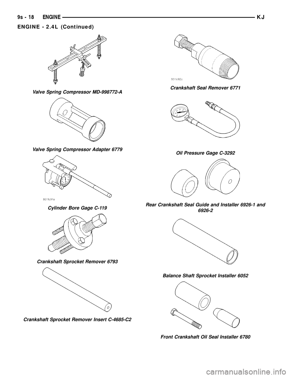
Valve Spring Compressor MD-998772-A
Valve Spring Compressor Adapter 6779
Cylinder Bore Gage C-119
Crankshaft Sprocket Remover 6793
Crankshaft Sprocket Remover Insert C-4685-C2
Crankshaft Seal Remover 6771
Oil Pressure Gage C-3292
Rear Crankshaft Seal Guide and Installer 6926-1 and
6926-2
Balance Shaft Sprocket Installer 6052
Front Crankshaft Oil Seal Installer 6780
9s - 18 ENGINEKJ
ENGINE - 2.4L (Continued)
Page 1316 of 1803
AIR CLEANER ELEMENT
REMOVAL - 2.4L
Housing removal is not necessary for element (fil-
ter) replacement.
(1) Disconnect air intake duct at side of element
cover.
(2) Pry up 2 spring clips from front of housing
cover (spring clips retain cover to housing).
(3) Release housing cover from locating tabs
located on rear of housing, and remove cover.
(4) Remove air cleaner element (filter) from hous-
ing.
(5) Clean inside of housing before replacing ele-
ment.
INSTALLATION - 2.4L
(1) Install element into housing.
(2) Position housing cover into housing locating
tabs.
(3) Pry up spring clips and lock cover to housing.
(4) Connect air intake duct.
If any air filter, air resonator, air intake tubes or
air filter housing clamps had been loosened or
removed, tighten them to 5 N´m (40 in. lbs.) torque.
CYLINDER HEAD
DESCRIPTION
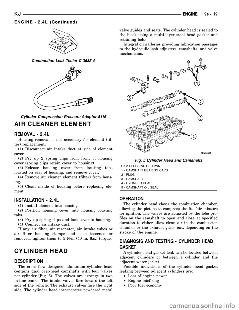
The cross flow designed, aluminum cylinder head
contains dual over-head camshafts with four valves
per cylinder (Fig. 5). The valves are arrange in two
in-line banks. The intake valves face toward the left
side of the vehicle. The exhaust valves face the right
side. The cylinder head incorporates powdered metalvalve guides and seats. The cylinder head is sealed to
the block using a multi-layer steel head gasket and
retaining bolts.
Integral oil galleries providing lubrication passages
to the hydraulic lash adjusters, camshafts, and valve
mechanisms.
OPERATION
The cylinder head closes the combustion chamber,
allowing the pistons to compress the fuel/air mixture
for ignition. The valves are actuated by the lobe pro-
files on the camshaft to open and close at specified
duration to either allow clean air in the combustion
chamber or the exhaust gases out; depending on the
stroke of the engine.
DIAGNOSIS AND TESTING - CYLINDER HEAD
GASKET
A cylinder head gasket leak can be located between
adjacent cylinders or between a cylinder and the
adjacent water jacket.
Possible indications of the cylinder head gasket
leaking between adjacent cylinders are:
²Loss of engine power
²Engine misfiring
²Poor fuel economy
Combustion Leak Tester C-3685-A
Cylinder Compression Pressure Adaptor 8116
Fig. 5 Cylinder Head and Camshafts
CAM PLUG - NOT SHOWN
1 - CAMSHAFT BEARING CAPS
2 - PLUG
3 - CAMSHAFT
4 - CYLINDER HEAD
5 - CAMSHAFT OIL SEAL
KJENGINE9s-19
ENGINE - 2.4L (Continued)
Page 1320 of 1803
(3) Install timing belt rear cover. (Refer to 9 -
ENGINE/VALVE TIMING/TIMING BELT / CHAIN
COVER(S) - INSTALLATION)
NOTE: Target ring tab should provide posative
snap-on fit on the camshaft.
(4) Install exhaust camshaft target ring with the
wordFRONTfacing forward.
(5) Install exhaust camshaft sensor.
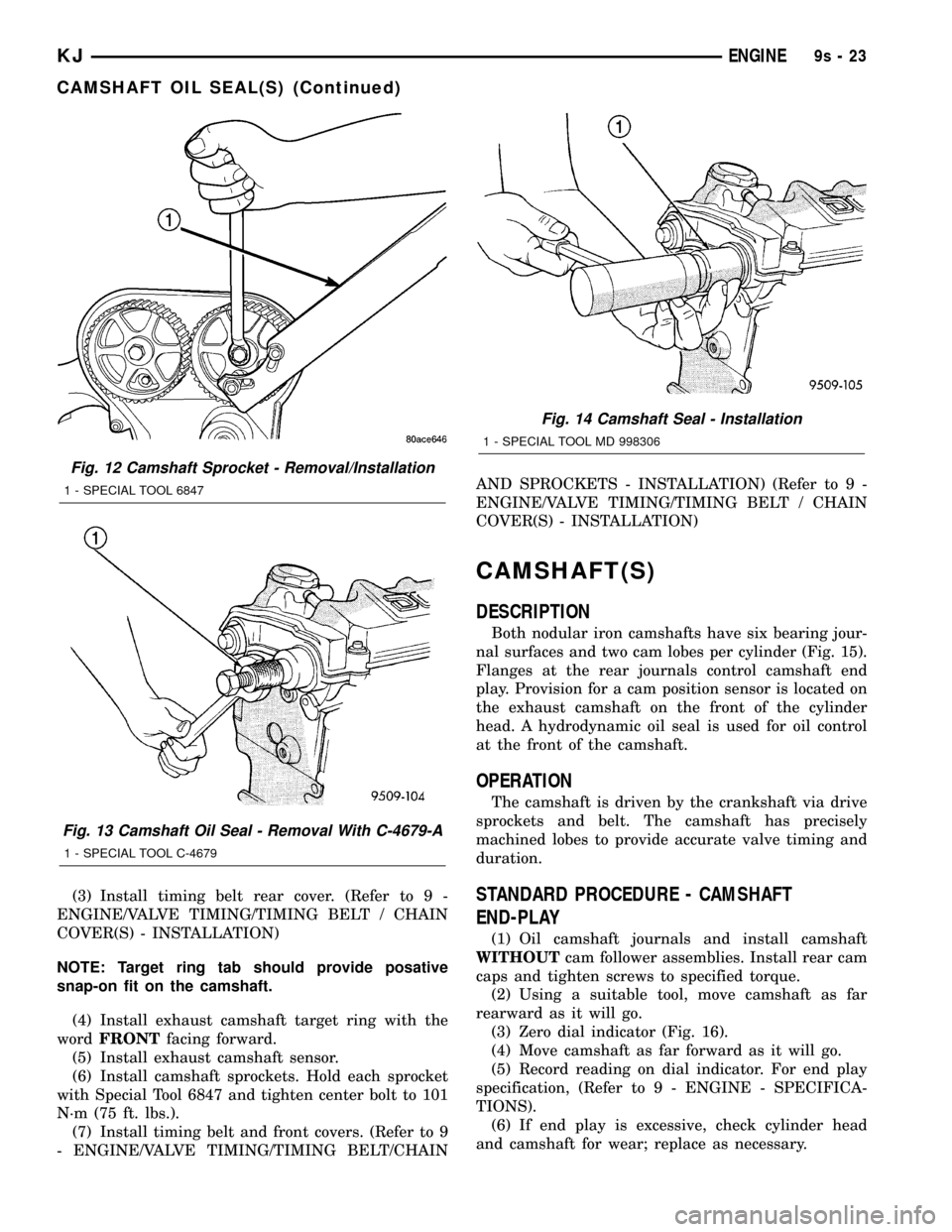
(6) Install camshaft sprockets. Hold each sprocket
with Special Tool 6847 and tighten center bolt to 101
N´m (75 ft. lbs.).
(7) Install timing belt and front covers. (Refer to 9
- ENGINE/VALVE TIMING/TIMING BELT/CHAINAND SPROCKETS - INSTALLATION) (Refer to 9 -
ENGINE/VALVE TIMING/TIMING BELT / CHAIN
COVER(S) - INSTALLATION)
CAMSHAFT(S)
DESCRIPTION
Both nodular iron camshafts have six bearing jour-
nal surfaces and two cam lobes per cylinder (Fig. 15).
Flanges at the rear journals control camshaft end
play. Provision for a cam position sensor is located on
the exhaust camshaft on the front of the cylinder
head. A hydrodynamic oil seal is used for oil control
at the front of the camshaft.
OPERATION
The camshaft is driven by the crankshaft via drive
sprockets and belt. The camshaft has precisely
machined lobes to provide accurate valve timing and
duration.
STANDARD PROCEDURE - CAMSHAFT
END-PLAY
(1) Oil camshaft journals and install camshaft
WITHOUTcam follower assemblies. Install rear cam
caps and tighten screws to specified torque.
(2) Using a suitable tool, move camshaft as far
rearward as it will go.
(3) Zero dial indicator (Fig. 16).
(4) Move camshaft as far forward as it will go.
(5) Record reading on dial indicator. For end play
specification, (Refer to 9 - ENGINE - SPECIFICA-
TIONS).
(6) If end play is excessive, check cylinder head
and camshaft for wear; replace as necessary.
Fig. 12 Camshaft Sprocket - Removal/Installation
1 - SPECIAL TOOL 6847
Fig. 13 Camshaft Oil Seal - Removal With C-4679-A
1 - SPECIAL TOOL C-4679
Fig. 14 Camshaft Seal - Installation
1 - SPECIAL TOOL MD 998306
KJENGINE9s-23
CAMSHAFT OIL SEAL(S) (Continued)
Page 1330 of 1803
OPERATION
The crankshaft transfers force generated by com-
bustion within the cylinder to the flywheel or flex-
plate.
STANDARD PROCEDURE - CRANKSHAFT END
PLAY
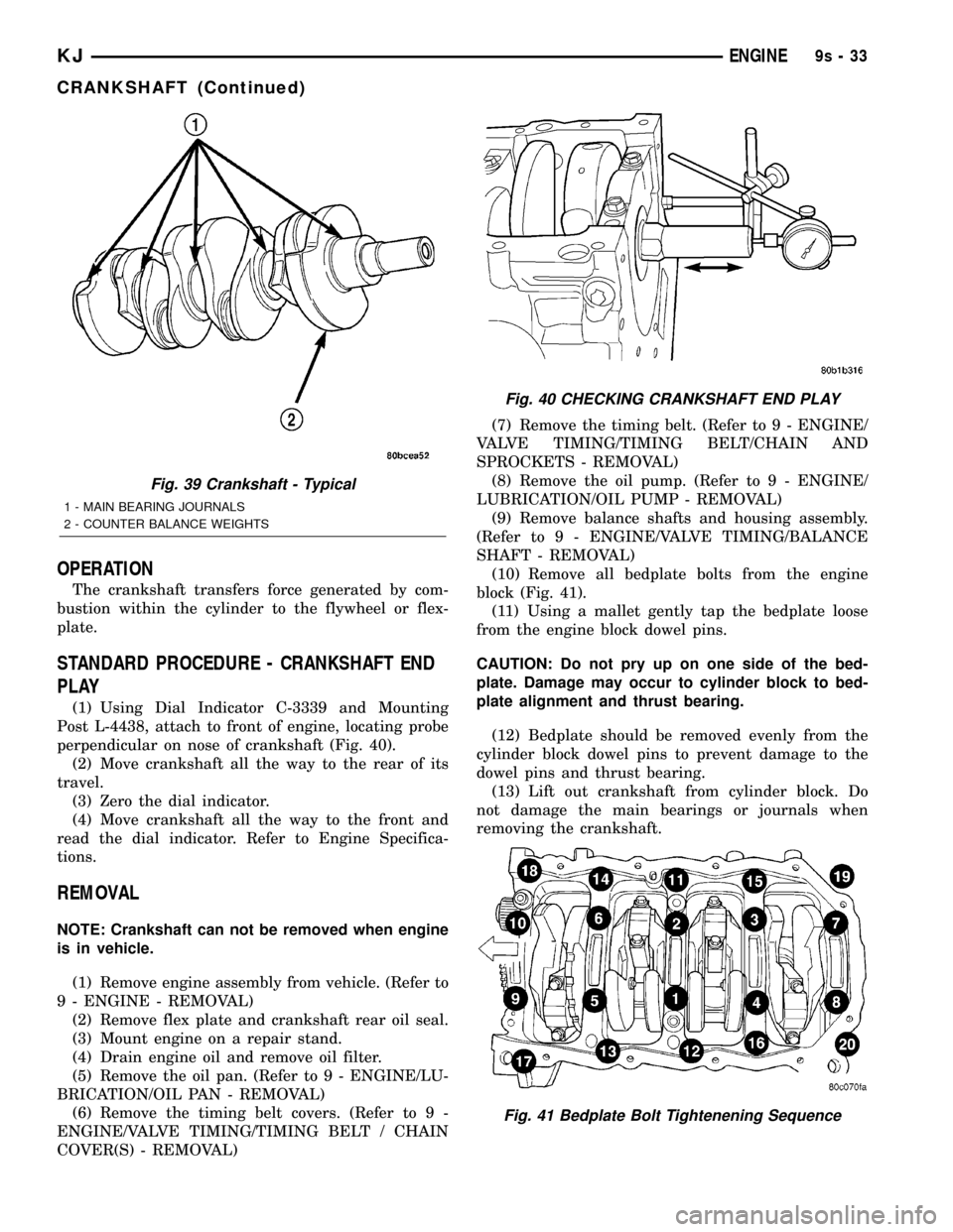
(1) Using Dial Indicator C-3339 and Mounting
Post L-4438, attach to front of engine, locating probe
perpendicular on nose of crankshaft (Fig. 40).
(2) Move crankshaft all the way to the rear of its
travel.
(3) Zero the dial indicator.
(4) Move crankshaft all the way to the front and
read the dial indicator. Refer to Engine Specifica-
tions.
REMOVAL
NOTE: Crankshaft can not be removed when engine
is in vehicle.
(1) Remove engine assembly from vehicle. (Refer to
9 - ENGINE - REMOVAL)
(2) Remove flex plate and crankshaft rear oil seal.
(3) Mount engine on a repair stand.
(4) Drain engine oil and remove oil filter.
(5) Remove the oil pan. (Refer to 9 - ENGINE/LU-
BRICATION/OIL PAN - REMOVAL)
(6) Remove the timing belt covers. (Refer to 9 -
ENGINE/VALVE TIMING/TIMING BELT / CHAIN
COVER(S) - REMOVAL)(7) Remove the timing belt. (Refer to 9 - ENGINE/
VALVE TIMING/TIMING BELT/CHAIN AND
SPROCKETS - REMOVAL)
(8) Remove the oil pump. (Refer to 9 - ENGINE/
LUBRICATION/OIL PUMP - REMOVAL)
(9) Remove balance shafts and housing assembly.
(Refer to 9 - ENGINE/VALVE TIMING/BALANCE
SHAFT - REMOVAL)
(10) Remove all bedplate bolts from the engine
block (Fig. 41).
(11) Using a mallet gently tap the bedplate loose
from the engine block dowel pins.
CAUTION: Do not pry up on one side of the bed-
plate. Damage may occur to cylinder block to bed-
plate alignment and thrust bearing.
(12) Bedplate should be removed evenly from the
cylinder block dowel pins to prevent damage to the
dowel pins and thrust bearing.
(13) Lift out crankshaft from cylinder block. Do
not damage the main bearings or journals when
removing the crankshaft.
Fig. 39 Crankshaft - Typical
1 - MAIN BEARING JOURNALS
2 - COUNTER BALANCE WEIGHTS
Fig. 40 CHECKING CRANKSHAFT END PLAY
Fig. 41 Bedplate Bolt Tightenening Sequence
KJENGINE9s-33
CRANKSHAFT (Continued)