fuel filter JEEP LIBERTY 2002 KJ / 1.G Owner's Manual
[x] Cancel search | Manufacturer: JEEP, Model Year: 2002, Model line: LIBERTY, Model: JEEP LIBERTY 2002 KJ / 1.GPages: 1803, PDF Size: 62.3 MB
Page 1396 of 1803

OPERATION
The fuel pressure regulator is a mechanical device
that is not controlled by engine vacuum or the Pow-
ertrain Control Module (PCM).
The regulator is calibrated to maintain fuel system
operating pressure of approximately 339 kPa +/- 34
kPa (49.2 psi +/- 5 psi) at the fuel injectors. It con-
tains a diaphragm, calibrated springs and a fuel
return valve.
The main fuel filteris not combinedwithin the
fuel pressure regulator as in other Jeeptmodels.
Three different fuel filters are used: 1. a serviceable,
separate, externally mounted, main fuel filter; 2. a
non-serviceable primary filter located on the bottom
of the electric fuel pump; 3. a non-serviceable second-
ary filter attached to the side of the fuel pump mod-
ule.
Fuel Flow:Fuel migrates into the fuel pump mod-
ule reservoir through a one-way check valve located
on the bottom of the module. This check valve pre-
vents the reservoir from running empty such as
when going up or down hills with a low amount of
fuel in the tank. A primary fuel filter (sock) is located
at the bottom of the electric fuel pump. Fuel is drawn
in through this filter, and up to the electric fuel
pump. High pressure fuel (unregulated) is supplied
from the electric fuel pump through a high-pressure
line to one of 3 fittings on the main fuel filter. If fuel
pressure at the pressure regulator exceeds approxi-
mately 49 psi, an internal diaphragm within the reg-
ulator closes, and excess fuel is routed through a
second fitting on the main fuel filter, and back into
the fuel tank (the fuel pressure regulator is installed
into the return side of the system). Pressure regu-
lated fuel is then delivered from the third fitting on
the fuel filter, up to and through the fuel rail, and on
to the fuel injectors.
A secondary fuel filter is attached to the side of the
fuel pump module. High-pressure from the electric
fuel pump causes a siphoning action across a passage
connected to this filter, and fuel is drawn into the
fuel pump module reservoir. This is used to help keep
the module reservoir full of fuel.
The fuel pressure regulator also acts as a check
valve to maintain some fuel pressure when the
engine is not operating. This will help to start the
engine. A second check valve is located at the outlet
of the fuel pump module housing.Refer to Fuel
Pump - Description and Operation for more
information. Also refer to the Fuel Pressure
Leak Down Test, and the Fuel Pump Pressure
Tests.
A separate fuel return line from the engine is not
used with this system.
REMOVAL
The fuel pressure regulator is located in the fuel
tank. It is attached to the bottom of the upper sec-
tion of the fuel pump module with a quick-connect
fitting (Fig. 19). The fuel pump module is supplied in
2 sections (upper and lower). To replace the pressure
regulator, the bottom section of the fuel pump mod-
ule must be replaced.
(1) Remove upper and lower sections of fuel pump
module from fuel tank. Refer to Fuel Pump Module
Removal/Installation.
(2) Replace lower section of fuel pump module
(includes fuel pressure regulator).
INSTALLATION
The fuel pressure regulator is located in the fuel
tank. It is attached to the bottom of the upper sec-
tion of the fuel pump module with a quick-connect
fitting. The fuel pump module is supplied in 2 sec-
tions (upper and lower). To replace the pressure reg-
ulator, the bottom section of the fuel pump module
must be replaced.
(1) Replace lower section of fuel pump module
(includes fuel pressure regulator).
(2) Install upper and lower sections of fuel pump
module to fuel tank. Refer to Fuel Pump Module
Installation.
Fig. 19 FUEL PRESSURE REGULATOR/SENDING
UNIT ELECTRICAL CONNECTOR
1 - UPPER SECTION OF PUMP MODULE
2 - QUICK-CONNECT FITTINGS
3 - FUEL PRESSURE REGULATOR
4 - 4-WIRE ELECTRICAL CONNECTOR
5 - FUEL TANK CHECK (CONTROL) VALVE
14 - 14 FUEL DELIVERYKJ
FUEL PRESSURE REGULATOR (Continued)
Page 1397 of 1803

FUEL PUMP
DESCRIPTION
The electric fuel pump is located inside of the fuel
pump module. A 12 volt, permanent magnet, electric
motor powers the fuel pump. The electric fuel pump
is not a separate, serviceable component.
OPERATION
Voltage to operate the electric pump is supplied
through the fuel pump relay.
Fuel is drawn in through a filter at the bottom of
the module and pushed through the electric motor
gearset to the pump outlet.
Check Valve Operation:The bottom section of
the fuel pump module contains a one-way check
valve to prevent fuel flow back into the tank and to
maintain fuel supply line pressure (engine warm)
when pump is not operational. It is also used to keep
the fuel supply line full of gasoline when pump is not
operational. After the vehicle has cooled down, fuel
pressure may drop to 0 psi (cold fluid contracts), but
liquid gasoline will remain in fuel supply line
between the check valve and fuel injectors.Fuel
pressure that has dropped to 0 psi on a cooled
down vehicle (engine off) is a normal condition.
Refer to the Fuel Pressure Leak Down Test for more
information.
The electric fuel pump is not a separate, service-
able component.
DIAGNOSIS AND TESTING
DIAGNOSIS AND TESTING - FUEL PUMP
CAPACITY TEST
Before performing this test, verify fuel pump
pressure. Refer to Fuel Pump Pressure Test.
Use this test in conjunction with the Fuel Pres-
sure Leak Down Test.
(1) Release fuel system pressure. Refer to Fuel
Pressure Release Procedure.
(2) Disconnect fuel supply line at fuel rail. Refer to
Quick-Connect Fittings. Some engines may require
air cleaner housing removal before line disconnection.
(3) Obtain correct Fuel Line Pressure Test Adapter
Tool Hose. Tool number 6539 is used for 5/16º fuel
lines and tool number 6631 is used for 3/8º fuel lines.
(4) Connect correct Fuel Line Pressure Test
Adapter Tool Hose into disconnected fuel supply line.
Insert other end of Adaptor Tool Hose into a gradu-
ated container.
(5) Remove fuel fill cap.(6) To activate fuel pump and pressurize system,
obtain DRBtscan tool and actuate ASD Fuel System
Test.
(7) A good fuel pump will deliver at least 1/10 liter
of fuel in 7 seconds. Do not operate fuel pump for
longer than 7 seconds with fuel line disconnected as
fuel pump module reservoir may run empty.
(a) If capacity is lower than specification, but
fuel pump can be heard operating through fuel fill
cap opening, check for a kinked/damaged fuel sup-
ply line somewhere between fuel rail and fuel
pump module.
(b) If line is not kinked/damaged, and fuel pres-
sure is OK, but capacity is low, replace fuel filter.
Refer to Fuel Filter Removal/Installation for addi-
tional information.
(c) If both fuel pressure and capacity are low,
replace bottom section of fuel pump module. Refer
to Fuel Pump Module Removal/Installation.
DIAGNOSIS AND TESTING - FUEL PUMP
PRESSURE TEST
Use this test in conjunction with the Fuel Pump
Capacity Test, Fuel Pressure Leak Down Test and
Fuel Pump Amperage Test found elsewhere in this
group.
Check Valve Operation:The bottom section of
the fuel pump module contains a one-way check
valve to prevent fuel flow back into the tank and to
maintain fuel supply line pressure (engine warm)
when pump is not operational. It is also used to keep
the fuel supply line full of gasoline when pump is not
operational. After the vehicle has cooled down, fuel
pressure may drop to 0 psi (cold fluid contracts), but
liquid gasoline will remain in fuel supply line
between the check valve and fuel injectors.Fuel
pressure that has dropped to 0 psi on a cooled
down vehicle (engine off) is a normal condition.
When the electric fuel pump is activated, fuel pres-
sure shouldimmediately(1±2 seconds) rise to spec-
ification.
The fuel system is equipped with a separate fuel
pump module mounted, fuel pressure regulator. The
fuel filter is remotely mounted. The fuel pressure
regulator is not controlled by engine vacuum.
WARNING: THE FUEL SYSTEM IS UNDER CON-
STANT FUEL PRESSURE EVEN WITH THE ENGINE
OFF. BEFORE DISCONNECTING FUEL LINE AT
FUEL RAIL, THIS PRESSURE MUST BE RELEASED.
REFER TO THE FUEL SYSTEM PRESSURE
RELEASE PROCEDURE.
KJFUEL DELIVERY 14 - 15
Page 1400 of 1803

(17) When LCS adapter test leads are attached
into relay cavities, fuel pumpwill be activated.
Determine fuel pump amperage on DRB screen.
Amperage should be below 10.0 amps. If amperage is
below 10.0 amps, and specifications for the Fuel
Pump Pressure, Fuel Pump Capacity and Fuel Pres-
sure Leak Down tests were met, the fuel pump mod-
ule is OK.
(18) If amperage is more than 10.0 amps, replace
fuel pump module assembly. The electric fuel pump
is not serviced separately.
(19) Disconnect test leads from relay cavities
immediately after testing.
FUEL PUMP MODULE
DESCRIPTION
The fuel pump module assembly is located in the
fuel tank (Fig. 1). The assembly is divided into 2±sec-
tions, upper and lower. The lower section is locked to
the bottom of the fuel tank. The complete assembly
contains the following components:
²A fuel pressure regulator
²A separate fuel pick-up, or inlet filter
²An electric fuel pump
²A lockring to retain upper section of pump mod-
ule to tank
²A rollover valve
²A vent fitting for ORVR system
²A soft gasket between tank flange and module
²A fuel gauge sending unit (fuel level sensor)
²Two fuel line connections (supply and return)
The fuel gauge sending unit may be serviced sepa-
rately. If the electrical fuel pump, primary inlet filter
or fuel pressure regulator require service, the lower
section of the fuel pump module must be replaced.
OPERATION
Refer to Fuel Pump, Inlet Filter, Fuel Pressure
Regulator and Fuel Gauge Sending Unit.
REMOVAL
The fuel pump module is divided into 2 sections,
upper and lower. To service the check (control) valve,
replace only the upper section. To service the fuel
gauge sending unit, remove the upper section. To ser-
vice the electric fuel pump, fuel pressure regulator or
primary inlet filter, remove both sections and replace
lower section.
Fuel tank removal will not be necessary for
fuel pump module removal. Access is from rear
cargo area.
(1) Four cargo holdown clamps are located inside
the vehicle on the floor of the rear cargo area.Remove the 2 rearward mounted clamps by drilling
out the clamp rivets.
(2) Fold carpeting forward to gain access to fuel
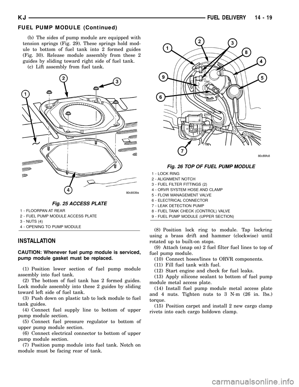
pump module access plate (Fig. 25).
(3) Remove 4 fuel pump module access plate nuts
(Fig. 25).
(4) While applying heat from a heat gun, carefully
pry up fuel pump module access plate. Take care not
to bend plate.
(5) Thoroughly clean area around top of pump
module to prevent contaminants from entering fuel
tank or fuel lines.
WARNING: THE FUEL SYSTEM IS UNDER A CON-
STANT PRESSURE EVEN WITH ENGINE OFF.
BEFORE SERVICING THE FUEL PUMP MODULE,
FUEL SYSTEM PRESSURE MUST BE RELEASED.
(6) Release fuel system pressure. Refer to Fuel
System Pressure Release procedure.
(7) Disconnect 2 fuel lines at fuel pump module
(Fig. 26) by pressing on 2 buttons at sides of fitting.
(8) Disconnect electrical connector (Fig. 26) at top
of fuel pump module by sliding red colored tab first
to unlock, and push grey colored tab down for
removal.
(9) Disconnect ORVR hose clamp and hose (Fig.
26) at pump module fitting.
(10) Remove module lockring (Fig. 26) using a
brass drift and hammer (counter-clockwise).
(11) Carefully lift upper section of pump module
(Fig. 26) from fuel tank exposing connections(lift
upper section from tank very slowly until rub-
ber gasket can be retained. If not, gasket will
fall into fuel tank.)
(a) Disconnect electrical connector (Fig. 27) at
bottom of upper pump module section.
(b) Disconnect fuel pressure regulator (Fig. 27)
at bottom of upper pump module section. Press on
2 locking tabs.
(c) Disconnect fuel return line (Fig. 27) at bot-
tom of upper pump module section. Press on 2
locking tabs.
(d) Remove upper section of pump module (Fig.
28) from fuel tank.
(12) Using an approved gas holding tank, drain
fuel tank through pump module opening.If check
(control) valve, or, only upper section of pump
module is being serviced, tank draining is not
necessary. If any other fuel pump module com-
ponent is being serviced, the tank must be com-
pletely drained to the bottom.
(13) To remove lower section of pump module from
fuel tank:
(a) Using finger pressure, push on plastic
release tab (Fig. 29) while sliding lock tab upward.
14 - 18 FUEL DELIVERYKJ
FUEL PUMP (Continued)
Page 1401 of 1803
(b) The sides of pump module are equipped with
tension springs (Fig. 29). These springs hold mod-
ule to bottom of fuel tank into 2 formed guides
(Fig. 30). Release module assembly from these 2
guides by sliding toward right side of fuel tank.
(c) Lift assembly from fuel tank.
INSTALLATION
CAUTION: Whenever fuel pump module is serviced,
pump module gasket must be replaced.
(1) Position lower section of fuel pump module
assembly into fuel tank.
(2) The bottom of fuel tank has 2 formed guides.
Lock module assembly into these 2 guides by sliding
toward left side of fuel tank.
(3) Push down on plastic tab to lock module to fuel
tank guides.
(4) Connect fuel supply line to bottom of upper
pump module section.
(5) Connect fuel pressure regulator to bottom of
upper pump module section.
(6) Connect electrical connector to bottom of upper
pump module section.
(7) Position pump module into fuel tank. Notch on
module must be facing rear of tank.(8) Position lock ring to module. Tap lockring
using a brass drift and hammer (clockwise) until
rotated up to built-on stops.
(9) Attach (snap on) 2 fuel filter fuel lines to top of
fuel pump module.
(10) Connect hoses/lines to ORVR components.
(11) Fill fuel tank with fuel.
(12) Start engine and check for fuel leaks.
(13) Apply silicone sealant to bottom of fuel pump
module metal access plate.
(14) Install fuel pump module metal access plate
and 4 nuts. Tighten nuts to 3 N´m (26 in. lbs.)
torque.
(15) Position carpet and install 2 new cargo clamp
rivets into each cargo holdown clamp.
Fig. 25 ACCESS PLATE
1 - FLOORPAN AT REAR
2 - FUEL PUMP MODULE ACCESS PLATE
3 - NUTS (4)
4 - OPENING TO PUMP MODULE
Fig. 26 TOP OF FUEL PUMP MODULE
1 - LOCK RING
2 - ALIGNMENT NOTCH
3 - FUEL FILTER FITTINGS (2)
4 - ORVR SYSTEM HOSE AND CLAMP
5 - FLOW MANAGEMENT VALVE
6 - ELECTRICAL CONNECTOR
7 - LEAK DETECTION PUMP
8 - FUEL TANK CHECK (CONTROL) VALVE
9 - FUEL PUMP MODULE (UPPER SECTION)
KJFUEL DELIVERY 14 - 19
FUEL PUMP MODULE (Continued)
Page 1408 of 1803
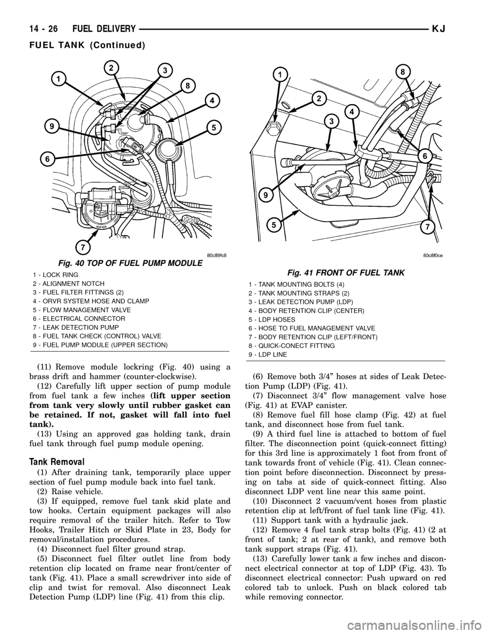
(11) Remove module lockring (Fig. 40) using a
brass drift and hammer (counter-clockwise).
(12) Carefully lift upper section of pump module
from fuel tank a few inches(lift upper section
from tank very slowly until rubber gasket can
be retained. If not, gasket will fall into fuel
tank).
(13) Using an approved gas holding tank, drain
fuel tank through fuel pump module opening.
Tank Removal
(1) After draining tank, temporarily place upper
section of fuel pump module back into fuel tank.
(2) Raise vehicle.
(3) If equipped, remove fuel tank skid plate and
tow hooks. Certain equipment packages will also
require removal of the trailer hitch. Refer to Tow
Hooks, Trailer Hitch or Skid Plate in 23, Body for
removal/installation procedures.
(4) Disconnect fuel filter ground strap.
(5) Disconnect fuel filter outlet line from body
retention clip located on frame near front/center of
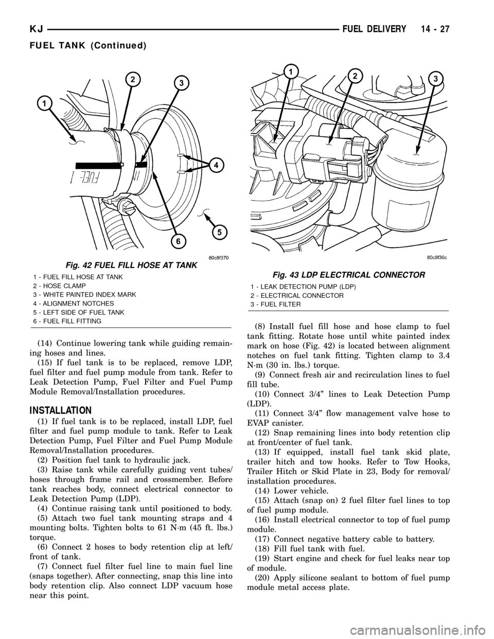
tank (Fig. 41). Place a small screwdriver into side of
clip and twist for removal. Also disconnect Leak
Detection Pump (LDP) line (Fig. 41) from this clip.(6) Remove both 3/4º hoses at sides of Leak Detec-
tion Pump (LDP) (Fig. 41).
(7) Disconnect 3/4º flow management valve hose
(Fig. 41) at EVAP canister.
(8) Remove fuel fill hose clamp (Fig. 42) at fuel
tank, and disconnect hose from fuel tank.
(9) A third fuel line is attached to bottom of fuel
filter. The disconnection point (quick-connect fitting)
for this 3rd line is approximately 1 foot from front of
tank towards front of vehicle (Fig. 41). Clean connec-
tion point before disconnection. Disconnect by press-
ing on tabs at side of quick-connect fitting. Also
disconnect LDP vent line near this same point.
(10) Disconnect 2 vacuum/vent hoses from plastic
retention clip at left/front of fuel tank line (Fig. 41).
(11) Support tank with a hydraulic jack.
(12) Remove 4 fuel tank strap bolts (Fig. 41) (2 at
front of tank; 2 at rear of tank), and remove both
tank support straps (Fig. 41).
(13) Carefully lower tank a few inches and discon-
nect electrical connector at top of LDP (Fig. 43). To
disconnect electrical connector: Push upward on red
colored tab to unlock. Push on black colored tab
while removing connector.
Fig. 40 TOP OF FUEL PUMP MODULE
1 - LOCK RING
2 - ALIGNMENT NOTCH
3 - FUEL FILTER FITTINGS (2)
4 - ORVR SYSTEM HOSE AND CLAMP
5 - FLOW MANAGEMENT VALVE
6 - ELECTRICAL CONNECTOR
7 - LEAK DETECTION PUMP
8 - FUEL TANK CHECK (CONTROL) VALVE
9 - FUEL PUMP MODULE (UPPER SECTION)Fig. 41 FRONT OF FUEL TANK
1 - TANK MOUNTING BOLTS (4)
2 - TANK MOUNTING STRAPS (2)
3 - LEAK DETECTION PUMP (LDP)
4 - BODY RETENTION CLIP (CENTER)
5 - LDP HOSES
6 - HOSE TO FUEL MANAGEMENT VALVE
7 - BODY RETENTION CLIP (LEFT/FRONT)
8 - QUICK-CONECT FITTING
9 - LDP LINE
14 - 26 FUEL DELIVERYKJ
FUEL TANK (Continued)
Page 1409 of 1803
(14) Continue lowering tank while guiding remain-
ing hoses and lines.
(15) If fuel tank is to be replaced, remove LDP,
fuel filter and fuel pump module from tank. Refer to
Leak Detection Pump, Fuel Filter and Fuel Pump
Module Removal/Installation procedures.
INSTALLATION
(1) If fuel tank is to be replaced, install LDP, fuel
filter and fuel pump module to tank. Refer to Leak
Detection Pump, Fuel Filter and Fuel Pump Module
Removal/Installation procedures.
(2) Position fuel tank to hydraulic jack.
(3) Raise tank while carefully guiding vent tubes/
hoses through frame rail and crossmember. Before
tank reaches body, connect electrical connector to
Leak Detection Pump (LDP).
(4) Continue raising tank until positioned to body.
(5) Attach two fuel tank mounting straps and 4
mounting bolts. Tighten bolts to 61 N´m (45 ft. lbs.)
torque.
(6) Connect 2 hoses to body retention clip at left/
front of tank.
(7) Connect fuel filter fuel line to main fuel line
(snaps together). After connecting, snap this line into
body retention clip. Also connect LDP vacuum hose
near this point.(8) Install fuel fill hose and hose clamp to fuel
tank fitting. Rotate hose until white painted index
mark on hose (Fig. 42) is located between alignment
notches on fuel tank fitting. Tighten clamp to 3.4
N´m (30 in. lbs.) torque.
(9) Connect fresh air and recirculation lines to fuel
fill tube.
(10) Connect 3/4º lines to Leak Detection Pump
(LDP).
(11) Connect 3/4º flow management valve hose to
EVAP canister.
(12) Snap remaining lines into body retention clip
at front/center of fuel tank.
(13) If equipped, install fuel tank skid plate,
trailer hitch and tow hooks. Refer to Tow Hooks,
Trailer Hitch or Skid Plate in 23, Body for removal/
installation procedures.
(14) Lower vehicle.
(15) Attach (snap on) 2 fuel filter fuel lines to top
of fuel pump module.
(16) Install electrical connector to top of fuel pump
module.
(17) Connect negative battery cable to battery.
(18) Fill fuel tank with fuel.
(19) Start engine and check for fuel leaks near top
of module.
(20) Apply silicone sealant to bottom of fuel pump
module metal access plate.
Fig. 42 FUEL FILL HOSE AT TANK
1 - FUEL FILL HOSE AT TANK
2 - HOSE CLAMP
3 - WHITE PAINTED INDEX MARK
4 - ALIGNMENT NOTCHES
5 - LEFT SIDE OF FUEL TANK
6 - FUEL FILL FITTINGFig. 43 LDP ELECTRICAL CONNECTOR
1 - LEAK DETECTION PUMP (LDP)
2 - ELECTRICAL CONNECTOR
3 - FUEL FILTER
KJFUEL DELIVERY 14 - 27
FUEL TANK (Continued)
Page 1410 of 1803
(21) Install fuel pump module metal access plate
and 4 nuts. Tighten nuts to 3 N´m (26 in. lbs.)
torque.
(22) Position carpet and install 2 new cargo clamp
rivets into each cargo holdown clamp.
FUEL TANK CHECK VALVE
DESCRIPTION
The fuel tank is equipped with a check valve. The
valve (also referred to as a control valve) is located in
the top section of the fuel pump module assembly
(Fig. 1).
OPERATION
The fuel tank check valve (also referred to as
either a control valve, one-way check valve or float
valve) will prevent fuel flow through the fuel tank
vent in the event of an accidental vehicle rollover. It
is also used as a part of the ORVR system. The
EVAP canister and ORVR system draw fuel vapors
from the fuel tank through this valve. Refer to ORVR
in Emissions for additional information.
The valve may be serviced by replacing the upper
section of the fuel pump module assembly.
REMOVAL
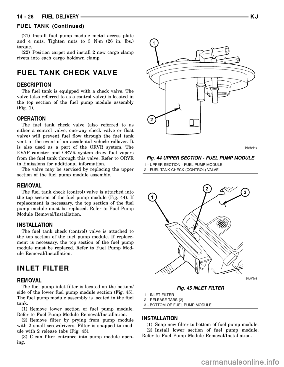
The fuel tank check (control) valve is attached into
the top section of the fuel pump module (Fig. 44). If
replacement is necessary, the top section of the fuel
pump module must be replaced. Refer to Fuel Pump
Module Removal/Installation.
INSTALLATION
The fuel tank check (control) valve is attached to
the top section of the fuel pump module. If replace-
ment is necessary, the top section of the fuel pump
module must be replaced. Refer to Fuel Pump Mod-
ule Removal/Installation.
INLET FILTER
REMOVAL
The fuel pump inlet filter is located on the bottom/
side of the lower fuel pump module section (Fig. 45).
The fuel pump module assembly is located in the fuel
tank.
(1) Remove lower section of fuel pump module.
Refer to Fuel Pump Module Removal/Installation.
(2) Remove filter by prying from pump module
with 2 small screwdrivers. Filter is snapped to mod-
ule with 2 release tabs (Fig. 45).
(3) Clean filter entrance into pump module open-
ing.
INSTALLATION
(1) Snap new filter to bottom of fuel pump module.
(2) Install lower section of fuel pump module.
Refer to Fuel Pump Module Removal/Installation.
Fig. 44 UPPER SECTION - FUEL PUMP MODULE
1 - UPPER SECTION - FUEL PUMP MODULE
2 - FUEL TANK CHECK (CONTROL) VALVE
Fig. 45 INLET FILTER
1 - INLET FILTER
2 - RELEASE TABS (2)
3 - BOTTOM OF FUEL PUMP MODULE
14 - 28 FUEL DELIVERYKJ
FUEL TANK (Continued)
Page 1425 of 1803
WARNING: THE EXHAUST MANIFOLD, EXHAUST
PIPES AND CATALYTIC CONVERTER BECOME
VERY HOT DURING ENGINE OPERATION. ALLOW
ENGINE TO COOL BEFORE REMOVING OXYGEN
SENSOR.
(1) Raise and support vehicle.
(2) Disconnect wire connector from O2S sensor.
CAUTION: When disconnecting sensor electrical
connector, do not pull directly on wire going into
sensor.
(3) Remove O2S sensor with an oxygen sensor
removal and installation tool.
(4) Clean threads in exhaust pipe using appropri-
ate tap.
INSTALLATION
Threads of new oxygen sensors are factory coated
with anti-seize compound to aid in removal.DO
NOT add any additional anti-seize compound to
threads of a new oxygen sensor.
(1) Install O2S sensor. Tighten to 30 N´m (22 ft.
lbs.) torque.
(2) Connect O2S sensor wire connector.
(3) Lower vehicle.
THROTTLE BODY
DESCRIPTION
The throttle body is located on the intake manifold.
Fuel does not enter the intake manifold through the
throttle body. Fuel is sprayed into the manifold by
the fuel injectors.
OPERATION
Filtered air from the air cleaner enters the intake
manifold through the throttle body. The throttle body
contains an air control passage controlled by an Idle
Air Control (IAC) motor. The air control passage is
used to supply air for idle conditions. A throttle valve
(plate) is used to supply air for above idle conditions.
Certain sensors are attached to the throttle body.
The accelerator pedal cable, speed control cable and
transmission control cable (when equipped) are con-
nected to the throttle body linkage arm.
A (factory adjusted) set screw is used to mechani-
cally limit the position of the throttle body throttle
plate.Never attempt to adjust the engine idle
speed using this screw.All idle speed functions are
controlled by the PCM.
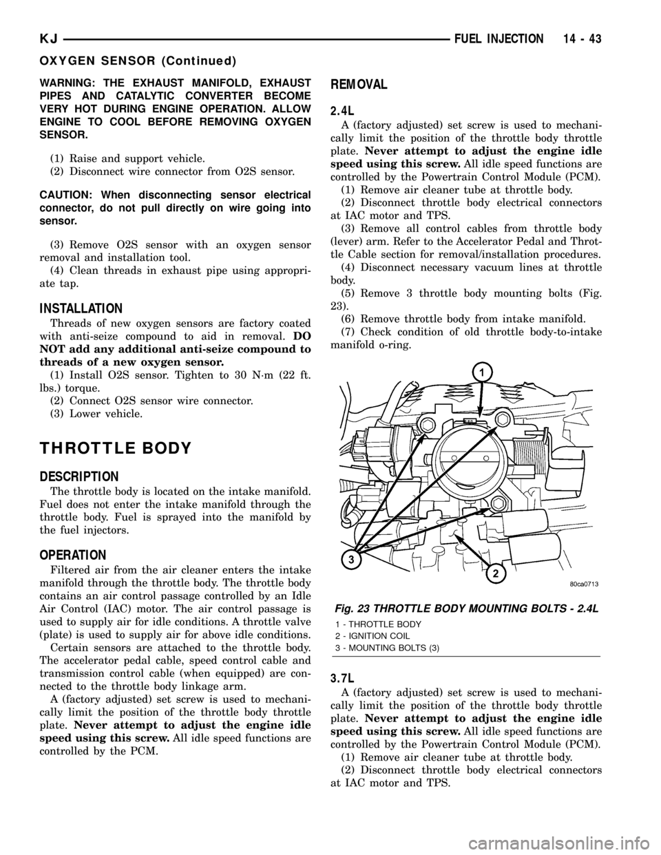
REMOVAL
2.4L
A (factory adjusted) set screw is used to mechani-
cally limit the position of the throttle body throttle
plate.Never attempt to adjust the engine idle
speed using this screw.All idle speed functions are
controlled by the Powertrain Control Module (PCM).
(1) Remove air cleaner tube at throttle body.
(2) Disconnect throttle body electrical connectors
at IAC motor and TPS.
(3) Remove all control cables from throttle body
(lever) arm. Refer to the Accelerator Pedal and Throt-
tle Cable section for removal/installation procedures.
(4) Disconnect necessary vacuum lines at throttle
body.
(5) Remove 3 throttle body mounting bolts (Fig.
23).
(6) Remove throttle body from intake manifold.
(7) Check condition of old throttle body-to-intake
manifold o-ring.
3.7L
A (factory adjusted) set screw is used to mechani-
cally limit the position of the throttle body throttle
plate.Never attempt to adjust the engine idle
speed using this screw.All idle speed functions are
controlled by the Powertrain Control Module (PCM).
(1) Remove air cleaner tube at throttle body.
(2) Disconnect throttle body electrical connectors
at IAC motor and TPS.
Fig. 23 THROTTLE BODY MOUNTING BOLTS - 2.4L
1 - THROTTLE BODY
2 - IGNITION COIL
3 - MOUNTING BOLTS (3)
KJFUEL INJECTION 14 - 43
OXYGEN SENSOR (Continued)
Page 1726 of 1803
an associated limp in will take two trips to illumi-
nate the MIL.
Refer to the Diagnostic Trouble Codes Description
Charts in this section and the appropriate Power-
train Diagnostic Procedure Manual for diagnostic
procedures.
DESCRIPTION - NON-MONITORED CIRCUITS
The PCM does not monitor the following circuits,
systems and conditions that could have malfunctions
causing driveability problems. The PCM might not
store diagnostic trouble codes for these conditions.
However, problems with these systems may cause the
PCM to store diagnostic trouble codes for other sys-
tems or components. For example, a fuel pressure
problem will not register a fault directly, but could
cause a rich/lean condition or misfire. This could
cause the PCM to store an oxygen sensor or misfire
diagnostic trouble code
FUEL PRESSURE
The fuel pressure regulator controls fuel system
pressure. The PCM cannot detect a clogged fuel
pump inlet filter, clogged in-line fuel filter, or a
pinched fuel supply or return line. However, these
could result in a rich or lean condition causing the
PCM to store an oxygen sensor or fuel system diag-
nostic trouble code.
SECONDARY IGNITION CIRCUIT
The PCM cannot detect an inoperative ignition coil,
fouled or worn spark plugs, ignition cross firing, or
open spark plug cables.
CYLINDER COMPRESSION
The PCM cannot detect uneven, low, or high engine
cylinder compression.
EXHAUST SYSTEM
The PCM cannot detect a plugged, restricted or
leaking exhaust system, although it may set a fuel
system fault.
FUEL INJECTOR MECHANICAL MALFUNCTIONS
The PCM cannot determine if a fuel injector is
clogged, the needle is sticking or if the wrong injectoris installed. However, these could result in a rich or
lean condition causing the PCM to store a diagnostic
trouble code for either misfire, an oxygen sensor, or
the fuel system.
EXCESSIVE OIL CONSUMPTION
Although the PCM monitors engine exhaust oxygen
content when the system is in closed loop, it cannot
determine excessive oil consumption.
THROTTLE BODY AIRFLOW
The PCM cannot detect a clogged or restricted air
cleaner inlet or filter element.
VACUUM ASSIST
The PCM cannot detect leaks or restrictions in the
vacuum circuits of vacuum assisted engine control
system devices. However, these could cause the PCM
to store a MAP sensor diagnostic trouble code and
cause a high idle condition.
PCM SYSTEM GROUND
The PCM cannot determine a poor system ground.
However, one or more diagnostic trouble codes may
be generated as a result of this condition. The mod-
ule should be mounted to the body at all times, also
during diagnostic.
PCM CONNECTOR ENGAGEMENT
The PCM may not be able to determine spread or
damaged connector pins. However, it might store
diagnostic trouble codes as a result of spread connec-
tor pins.
DESCRIPTION - HIGH AND LOW LIMITS
The PCM compares input signal voltages from each
input device with established high and low limits for
the device. If the input voltage is not within limits
and other criteria are met, the PCM stores a diagnos-
tic trouble code in memory. Other diagnostic trouble
code criteria might include engine RPM limits or
input voltages from other sensors or switches that
must be present before verifying a diagnostic trouble
code condition.
DESCRIPTION - LOAD VALUE
ENGINE IDLE/NEUTRAL 2500 RPM/NEUTRAL
All Engines 2% to 8% of Maximum Load 9% to 17% of Maximum Load
25 - 20 EMISSIONS CONTROLKJ
EMISSIONS CONTROL (Continued)
Page 1731 of 1803
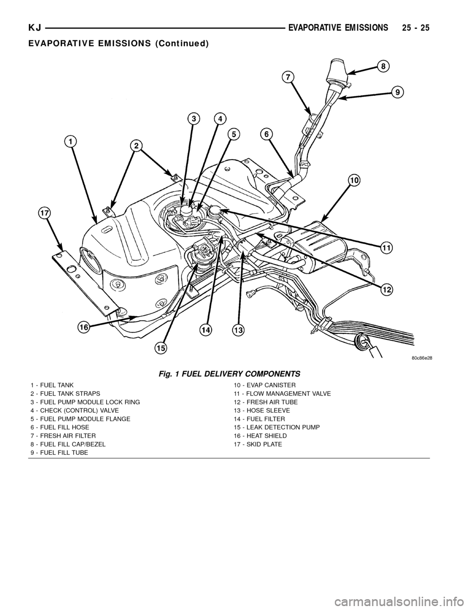
Fig. 1 FUEL DELIVERY COMPONENTS
1 - FUEL TANK 10 - EVAP CANISTER
2 - FUEL TANK STRAPS 11 - FLOW MANAGEMENT VALVE
3 - FUEL PUMP MODULE LOCK RING 12 - FRESH AIR TUBE
4 - CHECK (CONTROL) VALVE 13 - HOSE SLEEVE
5 - FUEL PUMP MODULE FLANGE 14 - FUEL FILTER
6 - FUEL FILL HOSE 15 - LEAK DETECTION PUMP
7 - FRESH AIR FILTER 16 - HEAT SHIELD
8 - FUEL FILL CAP/BEZEL 17 - SKID PLATE
9 - FUEL FILL TUBE
KJEVAPORATIVE EMISSIONS 25 - 25
EVAPORATIVE EMISSIONS (Continued)