Fuel system JEEP LIBERTY 2002 KJ / 1.G Manual Online
[x] Cancel search | Manufacturer: JEEP, Model Year: 2002, Model line: LIBERTY, Model: JEEP LIBERTY 2002 KJ / 1.GPages: 1803, PDF Size: 62.3 MB
Page 1401 of 1803
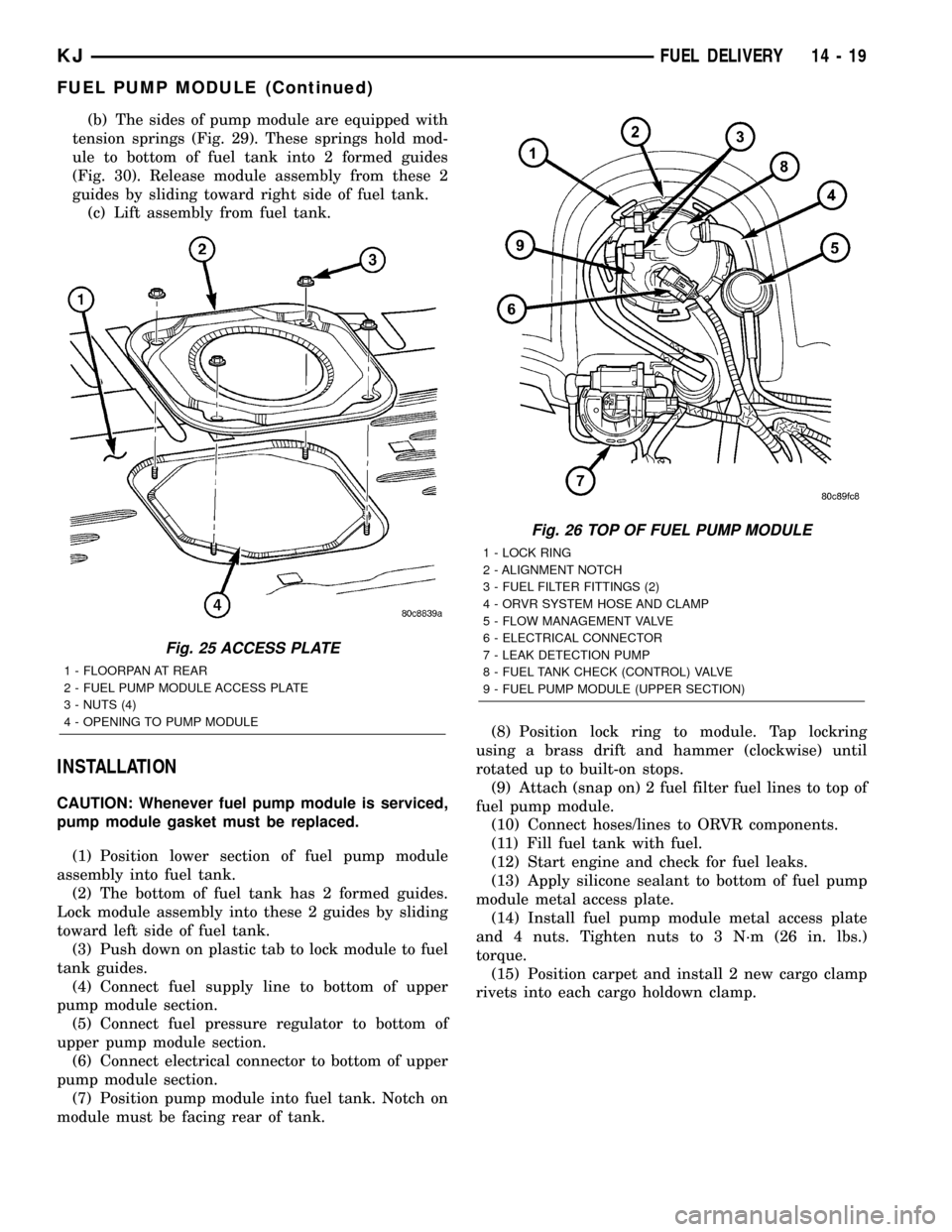
(b) The sides of pump module are equipped with
tension springs (Fig. 29). These springs hold mod-
ule to bottom of fuel tank into 2 formed guides
(Fig. 30). Release module assembly from these 2
guides by sliding toward right side of fuel tank.
(c) Lift assembly from fuel tank.
INSTALLATION
CAUTION: Whenever fuel pump module is serviced,
pump module gasket must be replaced.
(1) Position lower section of fuel pump module
assembly into fuel tank.
(2) The bottom of fuel tank has 2 formed guides.
Lock module assembly into these 2 guides by sliding
toward left side of fuel tank.
(3) Push down on plastic tab to lock module to fuel
tank guides.
(4) Connect fuel supply line to bottom of upper
pump module section.
(5) Connect fuel pressure regulator to bottom of
upper pump module section.
(6) Connect electrical connector to bottom of upper
pump module section.
(7) Position pump module into fuel tank. Notch on
module must be facing rear of tank.(8) Position lock ring to module. Tap lockring
using a brass drift and hammer (clockwise) until
rotated up to built-on stops.
(9) Attach (snap on) 2 fuel filter fuel lines to top of
fuel pump module.
(10) Connect hoses/lines to ORVR components.
(11) Fill fuel tank with fuel.
(12) Start engine and check for fuel leaks.
(13) Apply silicone sealant to bottom of fuel pump
module metal access plate.
(14) Install fuel pump module metal access plate
and 4 nuts. Tighten nuts to 3 N´m (26 in. lbs.)
torque.
(15) Position carpet and install 2 new cargo clamp
rivets into each cargo holdown clamp.
Fig. 25 ACCESS PLATE
1 - FLOORPAN AT REAR
2 - FUEL PUMP MODULE ACCESS PLATE
3 - NUTS (4)
4 - OPENING TO PUMP MODULE
Fig. 26 TOP OF FUEL PUMP MODULE
1 - LOCK RING
2 - ALIGNMENT NOTCH
3 - FUEL FILTER FITTINGS (2)
4 - ORVR SYSTEM HOSE AND CLAMP
5 - FLOW MANAGEMENT VALVE
6 - ELECTRICAL CONNECTOR
7 - LEAK DETECTION PUMP
8 - FUEL TANK CHECK (CONTROL) VALVE
9 - FUEL PUMP MODULE (UPPER SECTION)
KJFUEL DELIVERY 14 - 19
FUEL PUMP MODULE (Continued)
Page 1403 of 1803
FUEL RAIL
DESCRIPTION
2.4L
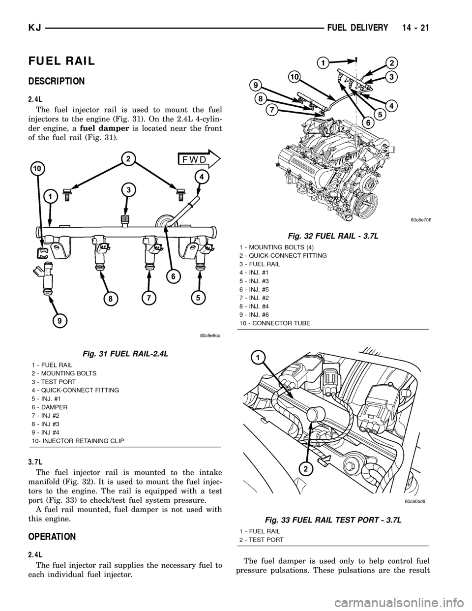
The fuel injector rail is used to mount the fuel
injectors to the engine (Fig. 31). On the 2.4L 4-cylin-
der engine, afuel damperis located near the front
of the fuel rail (Fig. 31).
3.7L
The fuel injector rail is mounted to the intake
manifold (Fig. 32). It is used to mount the fuel injec-
tors to the engine. The rail is equipped with a test
port (Fig. 33) to check/test fuel system pressure.
A fuel rail mounted, fuel damper is not used with
this engine.
OPERATION
2.4L
The fuel injector rail supplies the necessary fuel to
each individual fuel injector.The fuel damper is used only to help control fuel
pressure pulsations. These pulsations are the result
Fig. 31 FUEL RAIL-2.4L
1 - FUEL RAIL
2 - MOUNTING BOLTS
3 - TEST PORT
4 - QUICK-CONNECT FITTING
5 - INJ. #1
6 - DAMPER
7 - INJ #2
8 - INJ #3
9 - INJ #4
10- INJECTOR RETAINING CLIP
Fig. 32 FUEL RAIL - 3.7L
1 - MOUNTING BOLTS (4)
2 - QUICK-CONNECT FITTING
3 - FUEL RAIL
4 - INJ. #1
5 - INJ. #3
6 - INJ. #5
7 - INJ. #2
8 - INJ. #4
9 - INJ. #6
10 - CONNECTOR TUBE
Fig. 33 FUEL RAIL TEST PORT - 3.7L
1 - FUEL RAIL
2 - TEST PORT
KJFUEL DELIVERY 14 - 21
Page 1404 of 1803
of the firing of the fuel injectors. It isnot usedas a
fuel pressure regulator. The fuel pressure regulator is
not mountedto the fuel rail on any engine. It is
located on the fuel tank mounted fuel pump module.
Refer to Fuel Pressure Regulator for additional infor-
mation.
The fuel rail is not repairable.
A quick-connect fitting with a safety latch is used
to attach the fuel line to the fuel rail.
3.7L
High pressure fuel from the fuel pump is routed to
the fuel rail. The fuel rail then supplies the neces-
sary fuel to each individual fuel injector.
A quick-connect fitting with a safety latch is used
to attach the fuel line to the fuel rail.
The fuel rail is not repairable.
REMOVAL
2.4L
WARNING: THE FUEL SYSTEM IS UNDER CON-
STANT PRESSURE EVEN WITH ENGINE OFF.
BEFORE SERVICING FUEL RAIL, FUEL SYSTEM
PRESSURE MUST BE RELEASED.
The fuel rail can be removed without removing the
intake manifold if the following procedures are fol-
lowed.(1) Remove fuel tank filler tube cap.
(2) Perform Fuel System Pressure Release Proce-
dure.
(3) Remove negative battery cable at battery.
(4) Remove air duct at throttle body.
(5) Disconnect fuel line latch clip and fuel line at
fuel rail. A special tool will be necessary for fuel line
disconnection. Refer to Quick-Connect Fittings.
(6) Remove necessary vacuum lines at throttle
body.
(7) Drain engine coolant and remove thermostat
and thermostat housing.
(8) Remove PCV hose and valve at valve cover.
(9) Remove 3 upper intake manifold mounting
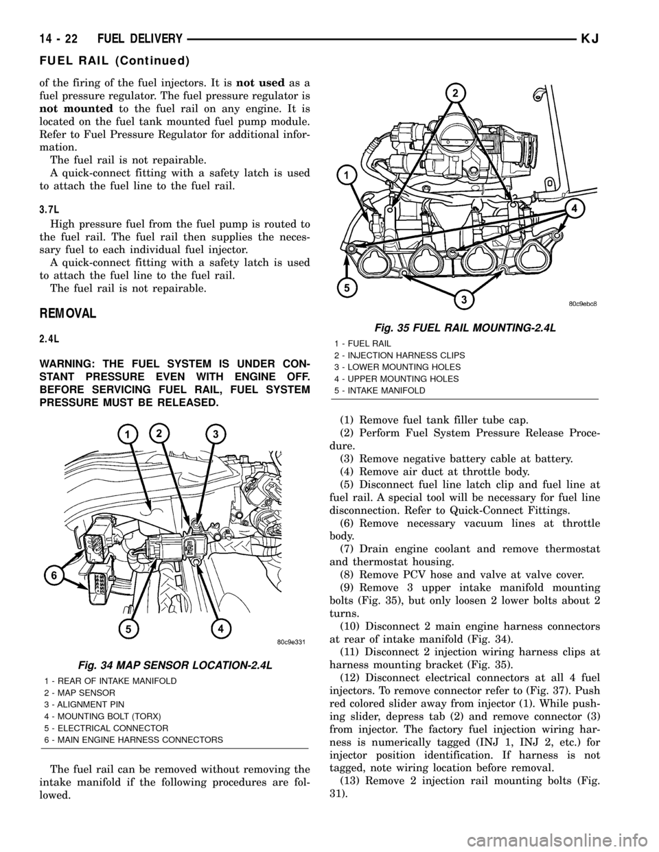
bolts (Fig. 35), but only loosen 2 lower bolts about 2
turns.
(10) Disconnect 2 main engine harness connectors
at rear of intake manifold (Fig. 34).
(11) Disconnect 2 injection wiring harness clips at
harness mounting bracket (Fig. 35).
(12) Disconnect electrical connectors at all 4 fuel
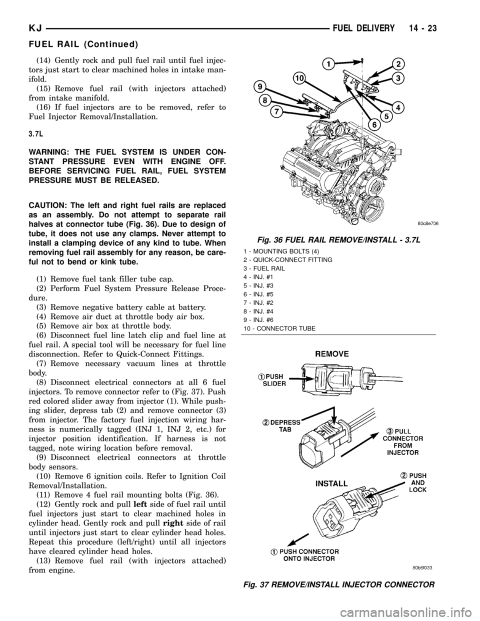
injectors. To remove connector refer to (Fig. 37). Push
red colored slider away from injector (1). While push-
ing slider, depress tab (2) and remove connector (3)
from injector. The factory fuel injection wiring har-
ness is numerically tagged (INJ 1, INJ 2, etc.) for
injector position identification. If harness is not
tagged, note wiring location before removal.
(13) Remove 2 injection rail mounting bolts (Fig.
31).
Fig. 34 MAP SENSOR LOCATION-2.4L
1 - REAR OF INTAKE MANIFOLD
2 - MAP SENSOR
3 - ALIGNMENT PIN
4 - MOUNTING BOLT (TORX)
5 - ELECTRICAL CONNECTOR
6 - MAIN ENGINE HARNESS CONNECTORS
Fig. 35 FUEL RAIL MOUNTING-2.4L
1 - FUEL RAIL
2 - INJECTION HARNESS CLIPS
3 - LOWER MOUNTING HOLES
4 - UPPER MOUNTING HOLES
5 - INTAKE MANIFOLD
14 - 22 FUEL DELIVERYKJ
FUEL RAIL (Continued)
Page 1405 of 1803
(14) Gently rock and pull fuel rail until fuel injec-
tors just start to clear machined holes in intake man-
ifold.
(15) Remove fuel rail (with injectors attached)
from intake manifold.
(16) If fuel injectors are to be removed, refer to
Fuel Injector Removal/Installation.
3.7L
WARNING: THE FUEL SYSTEM IS UNDER CON-
STANT PRESSURE EVEN WITH ENGINE OFF.
BEFORE SERVICING FUEL RAIL, FUEL SYSTEM
PRESSURE MUST BE RELEASED.
CAUTION: The left and right fuel rails are replaced
as an assembly. Do not attempt to separate rail
halves at connector tube (Fig. 36). Due to design of
tube, it does not use any clamps. Never attempt to
install a clamping device of any kind to tube. When
removing fuel rail assembly for any reason, be care-
ful not to bend or kink tube.
(1) Remove fuel tank filler tube cap.
(2) Perform Fuel System Pressure Release Proce-
dure.
(3) Remove negative battery cable at battery.
(4) Remove air duct at throttle body air box.
(5) Remove air box at throttle body.
(6) Disconnect fuel line latch clip and fuel line at
fuel rail. A special tool will be necessary for fuel line
disconnection. Refer to Quick-Connect Fittings.
(7) Remove necessary vacuum lines at throttle
body.
(8) Disconnect electrical connectors at all 6 fuel
injectors. To remove connector refer to (Fig. 37). Push
red colored slider away from injector (1). While push-
ing slider, depress tab (2) and remove connector (3)
from injector. The factory fuel injection wiring har-
ness is numerically tagged (INJ 1, INJ 2, etc.) for
injector position identification. If harness is not
tagged, note wiring location before removal.
(9) Disconnect electrical connectors at throttle
body sensors.
(10) Remove 6 ignition coils. Refer to Ignition Coil
Removal/Installation.
(11) Remove 4 fuel rail mounting bolts (Fig. 36).
(12) Gently rock and pullleftside of fuel rail until
fuel injectors just start to clear machined holes in
cylinder head. Gently rock and pullrightside of rail
until injectors just start to clear cylinder head holes.
Repeat this procedure (left/right) until all injectors
have cleared cylinder head holes.
(13) Remove fuel rail (with injectors attached)
from engine.
Fig. 36 FUEL RAIL REMOVE/INSTALL - 3.7L
1 - MOUNTING BOLTS (4)
2 - QUICK-CONNECT FITTING
3 - FUEL RAIL
4 - INJ. #1
5 - INJ. #3
6 - INJ. #5
7 - INJ. #2
8 - INJ. #4
9 - INJ. #6
10 - CONNECTOR TUBE
Fig. 37 REMOVE/INSTALL INJECTOR CONNECTOR
KJFUEL DELIVERY 14 - 23
FUEL RAIL (Continued)
Page 1406 of 1803
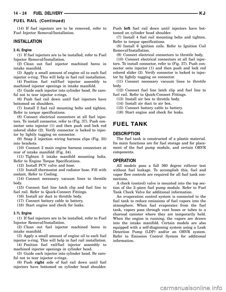
(14) If fuel injectors are to be removed, refer to
Fuel Injector Removal/Installation.
INSTALLATION
2.4L Engine
(1) If fuel injectors are to be installed, refer to Fuel
Injector Removal/Installation.
(2) Clean out fuel injector machined bores in
intake manifold.
(3) Apply a small amount of engine oil to each fuel
injector o-ring. This will help in fuel rail installation.
(4) Position fuel rail/fuel injector assembly to
machined injector openings in intake manifold.
(5) Guide each injector into cylinder head. Be care-
ful not to tear injector o-rings.
(6) Push fuel rail down until fuel injectors have
bottomed on shoulders.
(7) Install 2 fuel rail mounting bolts and tighten.
Refer to torque specifications.
(8) Connect electrical connectors at all fuel injec-
tors. To install connector, refer to (Fig. 37). Push con-
nector onto injector (1) and then push and lock red
colored slider (2). Verify connector is locked to injec-
tor by lightly tugging on connector.
(9) Snap 2 injection wiring harness clips (Fig. 35)
into brackets.
(10) Connect 2 main engine harness connectors at
rear of intake manifold (Fig. 34).
(11) Tighten 5 intake manifold mounting bolts.
Refer to Engine Torque Specifications.
(12) Install PCV valve and hose.
(13) Install thermostat and radiator hose. Fill with
coolant. Refer to Cooling.
(14) Connect necessary vacuum lines to throttle
body.
(15) Connect fuel line latch clip and fuel line to
fuel rail. Refer to Quick-Connect Fittings.
(16) Install air duct to throttle body.
(17) Connect battery cable to battery.
(18) Start engine and check for leaks.
3.7L Engine
(1) If fuel injectors are to be installed, refer to Fuel
Injector Removal/Installation.
(2) Clean out fuel injector machined bores in
intake manifold.
(3) Apply a small amount of engine oil to each fuel
injector o-ring. This will help in fuel rail installation.
(4) Position fuel rail/fuel injector assembly to
machined injector openings in cylinder head.
(5) Guide each injector into cylinder head. Be care-
ful not to tear injector o-rings.
(6) Pushrightside of fuel rail down until fuel
injectors have bottomed on cylinder head shoulder.Pushleftfuel rail down until injectors have bot-
tomed on cylinder head shoulder.
(7) Install 4 fuel rail mounting bolts and tighten.
Refer to torque specifications.
(8) Install 6 ignition coils. Refer to Ignition Coil
Removal/Installation.
(9) Connect electrical connectors to throttle body.
(10) Connect electrical connectors at all fuel injec-
tors. To install connector, refer to (Fig. 37). Push con-
nector onto injector (1) and then push and lock red
colored slider (2). Verify connector is locked to injec-
tor by lightly tugging on connector.
(11) Connect necessary vacuum lines to throttle
body.
(12) Connect fuel line latch clip and fuel line to
fuel rail. Refer to Quick-Connect Fittings.
(13) Install air box to throttle body.
(14) Install air duct to air box.
(15) Connect battery cable to battery.
(16) Start engine and check for leaks.
FUEL TANK
DESCRIPTION
The fuel tank is constructed of a plastic material.
Its main functions are for fuel storage and for place-
ment of the fuel pump module, and certain ORVR
components.
OPERATION
All models pass a full 360 degree rollover test
without fuel leakage. To accomplish this, fuel and
vapor flow controls are required for all fuel tank con-
nections.
A check (control) valve is mounted into the top sec-
tion of the 2±piece fuel pump module. Refer to Fuel
Tank Check Valve for additional information.
An evaporation control system is connected to the
fuel tank to reduce emissions of fuel vapors into the
atmosphere. When fuel evaporates from the fuel
tank, vapors pass through vent hoses or tubes to a
charcoal canister where they are temporarily held.
When the engine is running, the vapors are drawn
into the intake manifold. Certain models are also
equipped with a self-diagnosing system using a Leak
Detection Pump (LDP) and/or an ORVR system.
Refer to Emission Control System for additional
information.
14 - 24 FUEL DELIVERYKJ
FUEL RAIL (Continued)
Page 1407 of 1803
REMOVAL
Fuel Tank Draining
WARNING: THE FUEL SYSTEM MAY BE UNDER
CONSTANT FUEL PRESSURE EVEN WITH THE
ENGINE OFF. THIS PRESSURE MUST BE
RELEASED BEFORE SERVICING FUEL TANK.
Two different procedures may be used to drain fuel
tank: removing fuel pump module access plate, or
using DRBtscan tool. Due to a one-way check valve
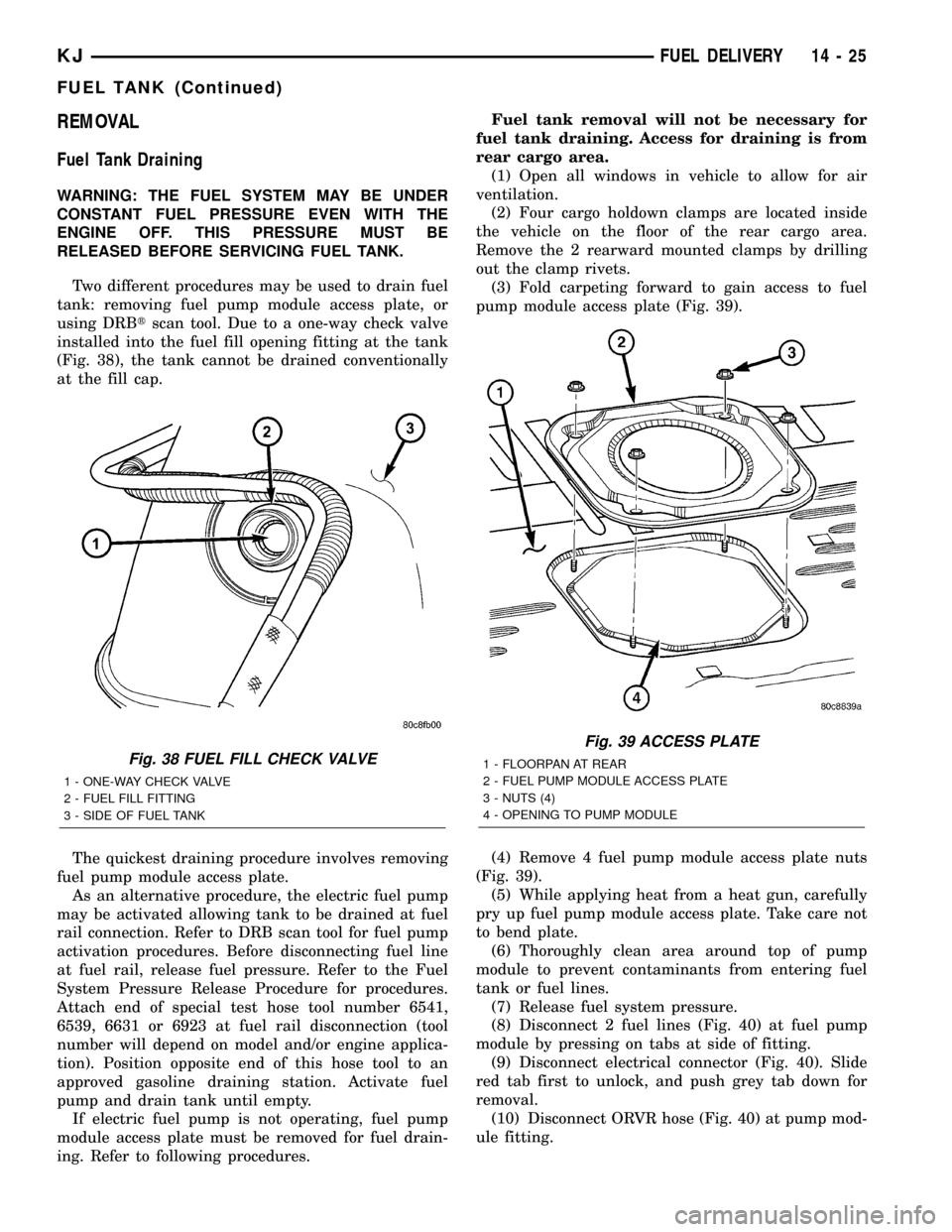
installed into the fuel fill opening fitting at the tank
(Fig. 38), the tank cannot be drained conventionally
at the fill cap.
The quickest draining procedure involves removing
fuel pump module access plate.
As an alternative procedure, the electric fuel pump
may be activated allowing tank to be drained at fuel
rail connection. Refer to DRB scan tool for fuel pump
activation procedures. Before disconnecting fuel line
at fuel rail, release fuel pressure. Refer to the Fuel
System Pressure Release Procedure for procedures.
Attach end of special test hose tool number 6541,
6539, 6631 or 6923 at fuel rail disconnection (tool
number will depend on model and/or engine applica-
tion). Position opposite end of this hose tool to an
approved gasoline draining station. Activate fuel
pump and drain tank until empty.
If electric fuel pump is not operating, fuel pump
module access plate must be removed for fuel drain-
ing. Refer to following procedures.Fuel tank removal will not be necessary for
fuel tank draining. Access for draining is from
rear cargo area.
(1) Open all windows in vehicle to allow for air
ventilation.
(2) Four cargo holdown clamps are located inside
the vehicle on the floor of the rear cargo area.
Remove the 2 rearward mounted clamps by drilling
out the clamp rivets.
(3) Fold carpeting forward to gain access to fuel
pump module access plate (Fig. 39).
(4) Remove 4 fuel pump module access plate nuts
(Fig. 39).
(5) While applying heat from a heat gun, carefully
pry up fuel pump module access plate. Take care not
to bend plate.
(6) Thoroughly clean area around top of pump
module to prevent contaminants from entering fuel
tank or fuel lines.
(7) Release fuel system pressure.
(8) Disconnect 2 fuel lines (Fig. 40) at fuel pump
module by pressing on tabs at side of fitting.
(9) Disconnect electrical connector (Fig. 40). Slide
red tab first to unlock, and push grey tab down for
removal.
(10) Disconnect ORVR hose (Fig. 40) at pump mod-
ule fitting.
Fig. 38 FUEL FILL CHECK VALVE
1 - ONE-WAY CHECK VALVE
2 - FUEL FILL FITTING
3 - SIDE OF FUEL TANK
Fig. 39 ACCESS PLATE
1 - FLOORPAN AT REAR
2 - FUEL PUMP MODULE ACCESS PLATE
3 - NUTS (4)
4 - OPENING TO PUMP MODULE
KJFUEL DELIVERY 14 - 25
FUEL TANK (Continued)
Page 1408 of 1803
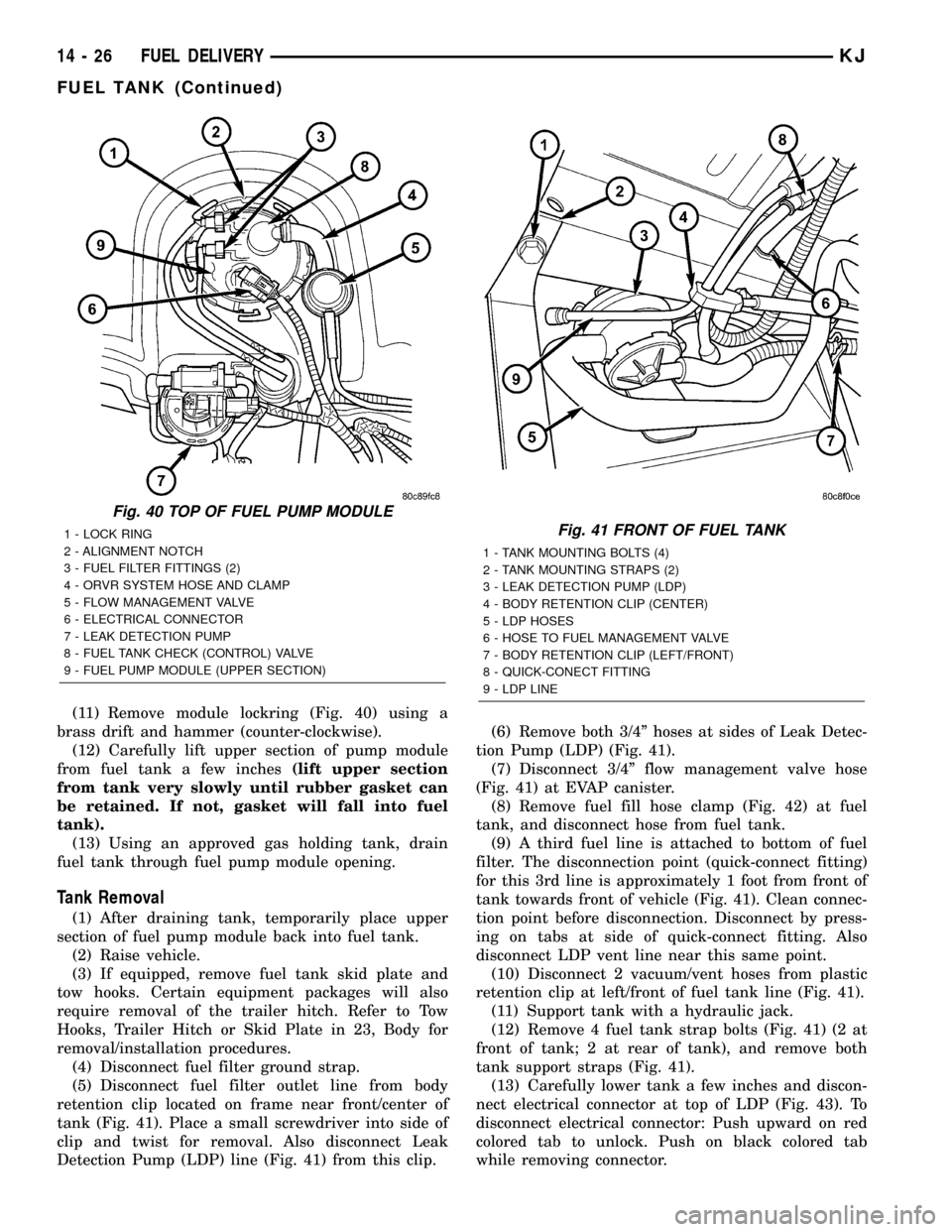
(11) Remove module lockring (Fig. 40) using a
brass drift and hammer (counter-clockwise).
(12) Carefully lift upper section of pump module
from fuel tank a few inches(lift upper section
from tank very slowly until rubber gasket can
be retained. If not, gasket will fall into fuel
tank).
(13) Using an approved gas holding tank, drain
fuel tank through fuel pump module opening.
Tank Removal
(1) After draining tank, temporarily place upper
section of fuel pump module back into fuel tank.
(2) Raise vehicle.
(3) If equipped, remove fuel tank skid plate and
tow hooks. Certain equipment packages will also
require removal of the trailer hitch. Refer to Tow
Hooks, Trailer Hitch or Skid Plate in 23, Body for
removal/installation procedures.
(4) Disconnect fuel filter ground strap.
(5) Disconnect fuel filter outlet line from body
retention clip located on frame near front/center of
tank (Fig. 41). Place a small screwdriver into side of
clip and twist for removal. Also disconnect Leak
Detection Pump (LDP) line (Fig. 41) from this clip.(6) Remove both 3/4º hoses at sides of Leak Detec-
tion Pump (LDP) (Fig. 41).
(7) Disconnect 3/4º flow management valve hose
(Fig. 41) at EVAP canister.
(8) Remove fuel fill hose clamp (Fig. 42) at fuel
tank, and disconnect hose from fuel tank.
(9) A third fuel line is attached to bottom of fuel
filter. The disconnection point (quick-connect fitting)
for this 3rd line is approximately 1 foot from front of
tank towards front of vehicle (Fig. 41). Clean connec-
tion point before disconnection. Disconnect by press-
ing on tabs at side of quick-connect fitting. Also
disconnect LDP vent line near this same point.
(10) Disconnect 2 vacuum/vent hoses from plastic
retention clip at left/front of fuel tank line (Fig. 41).
(11) Support tank with a hydraulic jack.
(12) Remove 4 fuel tank strap bolts (Fig. 41) (2 at
front of tank; 2 at rear of tank), and remove both
tank support straps (Fig. 41).
(13) Carefully lower tank a few inches and discon-
nect electrical connector at top of LDP (Fig. 43). To
disconnect electrical connector: Push upward on red
colored tab to unlock. Push on black colored tab
while removing connector.
Fig. 40 TOP OF FUEL PUMP MODULE
1 - LOCK RING
2 - ALIGNMENT NOTCH
3 - FUEL FILTER FITTINGS (2)
4 - ORVR SYSTEM HOSE AND CLAMP
5 - FLOW MANAGEMENT VALVE
6 - ELECTRICAL CONNECTOR
7 - LEAK DETECTION PUMP
8 - FUEL TANK CHECK (CONTROL) VALVE
9 - FUEL PUMP MODULE (UPPER SECTION)Fig. 41 FRONT OF FUEL TANK
1 - TANK MOUNTING BOLTS (4)
2 - TANK MOUNTING STRAPS (2)
3 - LEAK DETECTION PUMP (LDP)
4 - BODY RETENTION CLIP (CENTER)
5 - LDP HOSES
6 - HOSE TO FUEL MANAGEMENT VALVE
7 - BODY RETENTION CLIP (LEFT/FRONT)
8 - QUICK-CONECT FITTING
9 - LDP LINE
14 - 26 FUEL DELIVERYKJ
FUEL TANK (Continued)
Page 1410 of 1803
(21) Install fuel pump module metal access plate
and 4 nuts. Tighten nuts to 3 N´m (26 in. lbs.)
torque.
(22) Position carpet and install 2 new cargo clamp
rivets into each cargo holdown clamp.
FUEL TANK CHECK VALVE
DESCRIPTION
The fuel tank is equipped with a check valve. The
valve (also referred to as a control valve) is located in
the top section of the fuel pump module assembly
(Fig. 1).
OPERATION
The fuel tank check valve (also referred to as
either a control valve, one-way check valve or float
valve) will prevent fuel flow through the fuel tank
vent in the event of an accidental vehicle rollover. It
is also used as a part of the ORVR system. The
EVAP canister and ORVR system draw fuel vapors
from the fuel tank through this valve. Refer to ORVR
in Emissions for additional information.
The valve may be serviced by replacing the upper
section of the fuel pump module assembly.
REMOVAL
The fuel tank check (control) valve is attached into
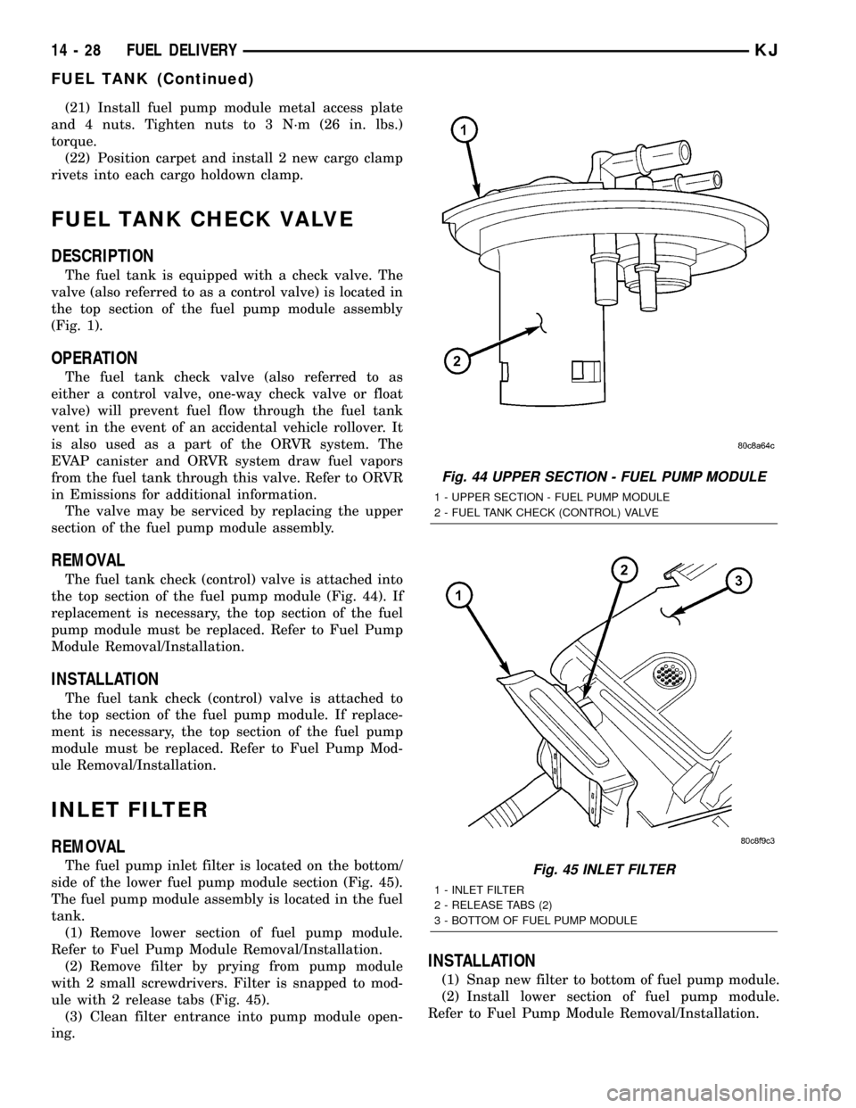
the top section of the fuel pump module (Fig. 44). If
replacement is necessary, the top section of the fuel
pump module must be replaced. Refer to Fuel Pump
Module Removal/Installation.
INSTALLATION
The fuel tank check (control) valve is attached to
the top section of the fuel pump module. If replace-
ment is necessary, the top section of the fuel pump
module must be replaced. Refer to Fuel Pump Mod-
ule Removal/Installation.
INLET FILTER
REMOVAL
The fuel pump inlet filter is located on the bottom/
side of the lower fuel pump module section (Fig. 45).
The fuel pump module assembly is located in the fuel
tank.
(1) Remove lower section of fuel pump module.
Refer to Fuel Pump Module Removal/Installation.
(2) Remove filter by prying from pump module
with 2 small screwdrivers. Filter is snapped to mod-
ule with 2 release tabs (Fig. 45).
(3) Clean filter entrance into pump module open-
ing.
INSTALLATION
(1) Snap new filter to bottom of fuel pump module.
(2) Install lower section of fuel pump module.
Refer to Fuel Pump Module Removal/Installation.
Fig. 44 UPPER SECTION - FUEL PUMP MODULE
1 - UPPER SECTION - FUEL PUMP MODULE
2 - FUEL TANK CHECK (CONTROL) VALVE
Fig. 45 INLET FILTER
1 - INLET FILTER
2 - RELEASE TABS (2)
3 - BOTTOM OF FUEL PUMP MODULE
14 - 28 FUEL DELIVERYKJ
FUEL TANK (Continued)
Page 1411 of 1803
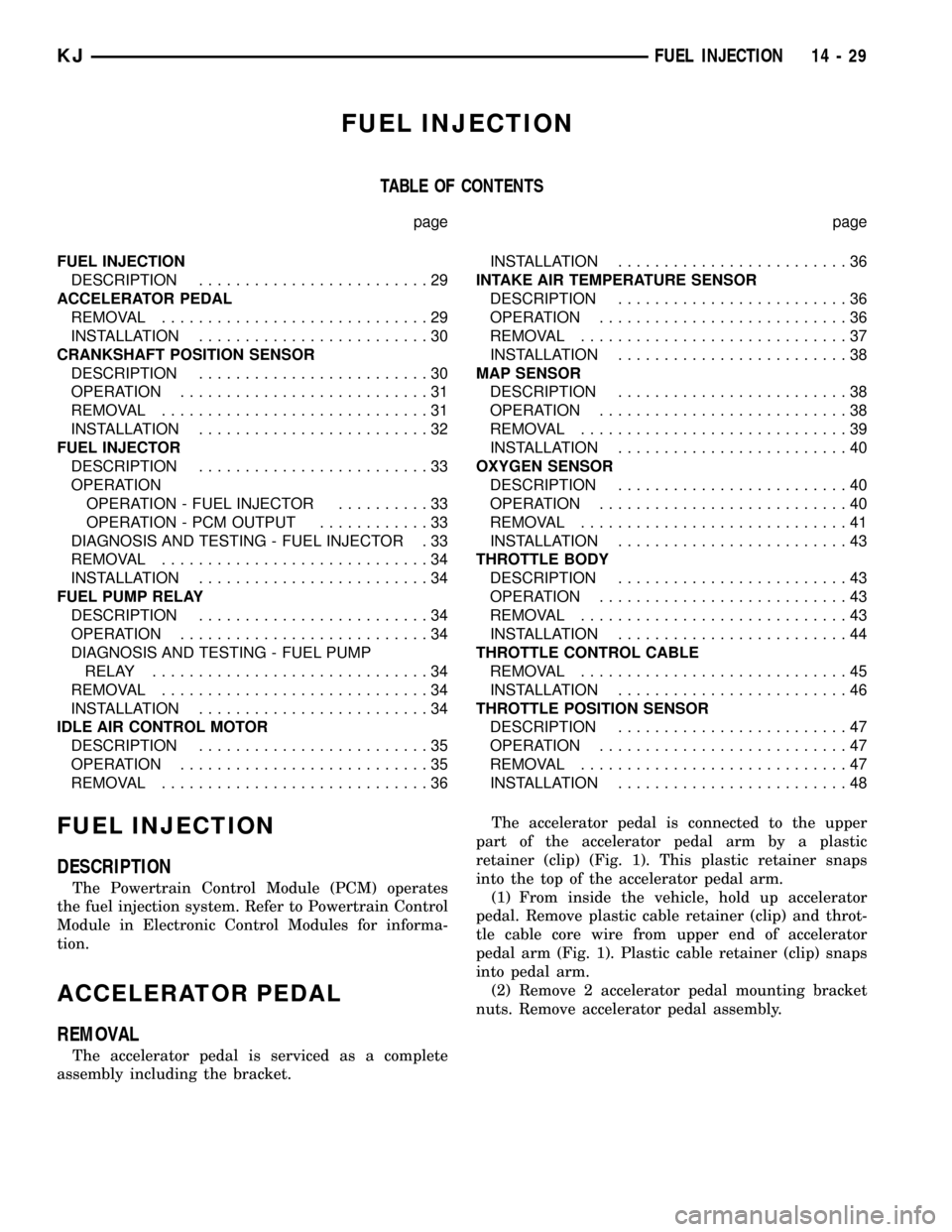
FUEL INJECTION
TABLE OF CONTENTS
page page
FUEL INJECTION
DESCRIPTION.........................29
ACCELERATOR PEDAL
REMOVAL.............................29
INSTALLATION.........................30
CRANKSHAFT POSITION SENSOR
DESCRIPTION.........................30
OPERATION...........................31
REMOVAL.............................31
INSTALLATION.........................32
FUEL INJECTOR
DESCRIPTION.........................33
OPERATION
OPERATION - FUEL INJECTOR..........33
OPERATION - PCM OUTPUT............33
DIAGNOSIS AND TESTING - FUEL INJECTOR . 33
REMOVAL.............................34
INSTALLATION.........................34
FUEL PUMP RELAY
DESCRIPTION.........................34
OPERATION...........................34
DIAGNOSIS AND TESTING - FUEL PUMP
RELAY..............................34
REMOVAL.............................34
INSTALLATION.........................34
IDLE AIR CONTROL MOTOR
DESCRIPTION.........................35
OPERATION...........................35
REMOVAL.............................36INSTALLATION.........................36
INTAKE AIR TEMPERATURE SENSOR
DESCRIPTION.........................36
OPERATION...........................36
REMOVAL.............................37
INSTALLATION.........................38
MAP SENSOR
DESCRIPTION.........................38
OPERATION...........................38
REMOVAL.............................39
INSTALLATION.........................40
OXYGEN SENSOR
DESCRIPTION.........................40
OPERATION...........................40
REMOVAL.............................41
INSTALLATION.........................43
THROTTLE BODY
DESCRIPTION.........................43
OPERATION...........................43
REMOVAL.............................43
INSTALLATION.........................44
THROTTLE CONTROL CABLE
REMOVAL.............................45
INSTALLATION.........................46
THROTTLE POSITION SENSOR
DESCRIPTION.........................47
OPERATION...........................47
REMOVAL.............................47
INSTALLATION.........................48
FUEL INJECTION
DESCRIPTION
The Powertrain Control Module (PCM) operates
the fuel injection system. Refer to Powertrain Control
Module in Electronic Control Modules for informa-
tion.
ACCELERATOR PEDAL
REMOVAL
The accelerator pedal is serviced as a complete
assembly including the bracket.The accelerator pedal is connected to the upper
part of the accelerator pedal arm by a plastic
retainer (clip) (Fig. 1). This plastic retainer snaps
into the top of the accelerator pedal arm.
(1) From inside the vehicle, hold up accelerator
pedal. Remove plastic cable retainer (clip) and throt-
tle cable core wire from upper end of accelerator
pedal arm (Fig. 1). Plastic cable retainer (clip) snaps
into pedal arm.
(2) Remove 2 accelerator pedal mounting bracket
nuts. Remove accelerator pedal assembly.
KJFUEL INJECTION 14 - 29
Page 1417 of 1803
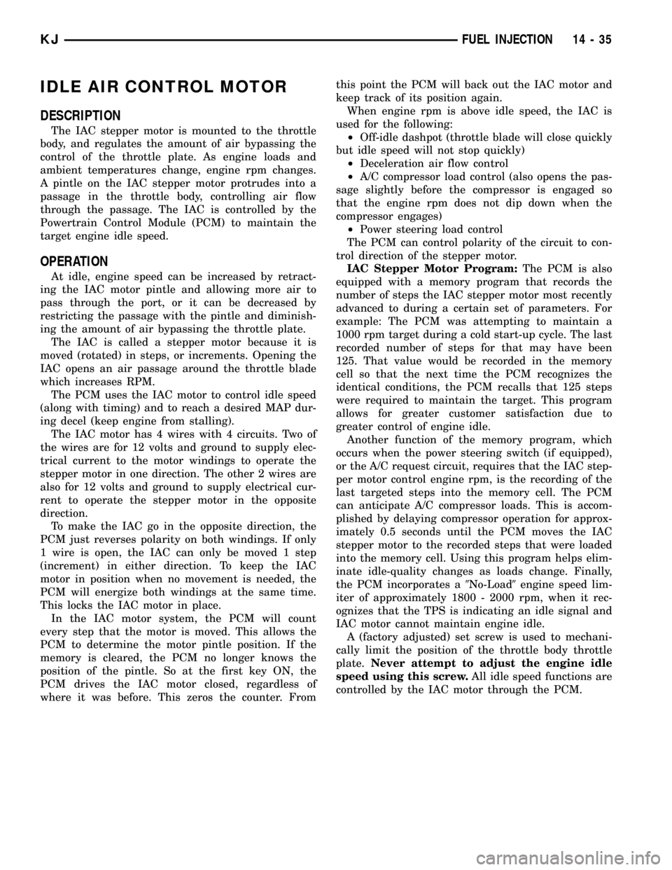
IDLE AIR CONTROL MOTOR
DESCRIPTION
The IAC stepper motor is mounted to the throttle
body, and regulates the amount of air bypassing the
control of the throttle plate. As engine loads and
ambient temperatures change, engine rpm changes.
A pintle on the IAC stepper motor protrudes into a
passage in the throttle body, controlling air flow
through the passage. The IAC is controlled by the
Powertrain Control Module (PCM) to maintain the
target engine idle speed.
OPERATION
At idle, engine speed can be increased by retract-
ing the IAC motor pintle and allowing more air to
pass through the port, or it can be decreased by
restricting the passage with the pintle and diminish-
ing the amount of air bypassing the throttle plate.
The IAC is called a stepper motor because it is
moved (rotated) in steps, or increments. Opening the
IAC opens an air passage around the throttle blade
which increases RPM.
The PCM uses the IAC motor to control idle speed
(along with timing) and to reach a desired MAP dur-
ing decel (keep engine from stalling).
The IAC motor has 4 wires with 4 circuits. Two of
the wires are for 12 volts and ground to supply elec-
trical current to the motor windings to operate the
stepper motor in one direction. The other 2 wires are
also for 12 volts and ground to supply electrical cur-
rent to operate the stepper motor in the opposite
direction.
To make the IAC go in the opposite direction, the
PCM just reverses polarity on both windings. If only
1 wire is open, the IAC can only be moved 1 step
(increment) in either direction. To keep the IAC
motor in position when no movement is needed, the
PCM will energize both windings at the same time.
This locks the IAC motor in place.
In the IAC motor system, the PCM will count
every step that the motor is moved. This allows the
PCM to determine the motor pintle position. If the
memory is cleared, the PCM no longer knows the
position of the pintle. So at the first key ON, the
PCM drives the IAC motor closed, regardless of
where it was before. This zeros the counter. Fromthis point the PCM will back out the IAC motor and
keep track of its position again.
When engine rpm is above idle speed, the IAC is
used for the following:
²Off-idle dashpot (throttle blade will close quickly
but idle speed will not stop quickly)
²Deceleration air flow control
²A/C compressor load control (also opens the pas-
sage slightly before the compressor is engaged so
that the engine rpm does not dip down when the
compressor engages)
²Power steering load control
The PCM can control polarity of the circuit to con-
trol direction of the stepper motor.
IAC Stepper Motor Program:The PCM is also
equipped with a memory program that records the
number of steps the IAC stepper motor most recently
advanced to during a certain set of parameters. For
example: The PCM was attempting to maintain a
1000 rpm target during a cold start-up cycle. The last
recorded number of steps for that may have been
125. That value would be recorded in the memory
cell so that the next time the PCM recognizes the
identical conditions, the PCM recalls that 125 steps
were required to maintain the target. This program
allows for greater customer satisfaction due to
greater control of engine idle.
Another function of the memory program, which
occurs when the power steering switch (if equipped),
or the A/C request circuit, requires that the IAC step-
per motor control engine rpm, is the recording of the
last targeted steps into the memory cell. The PCM
can anticipate A/C compressor loads. This is accom-
plished by delaying compressor operation for approx-
imately 0.5 seconds until the PCM moves the IAC
stepper motor to the recorded steps that were loaded
into the memory cell. Using this program helps elim-
inate idle-quality changes as loads change. Finally,
the PCM incorporates a9No-Load9engine speed lim-
iter of approximately 1800 - 2000 rpm, when it rec-
ognizes that the TPS is indicating an idle signal and
IAC motor cannot maintain engine idle.
A (factory adjusted) set screw is used to mechani-
cally limit the position of the throttle body throttle
plate.Never attempt to adjust the engine idle
speed using this screw.All idle speed functions are
controlled by the IAC motor through the PCM.
KJFUEL INJECTION 14 - 35