Psi JEEP LIBERTY 2002 KJ / 1.G Workshop Manual
[x] Cancel search | Manufacturer: JEEP, Model Year: 2002, Model line: LIBERTY, Model: JEEP LIBERTY 2002 KJ / 1.GPages: 1803, PDF Size: 62.3 MB
Page 8 of 1803
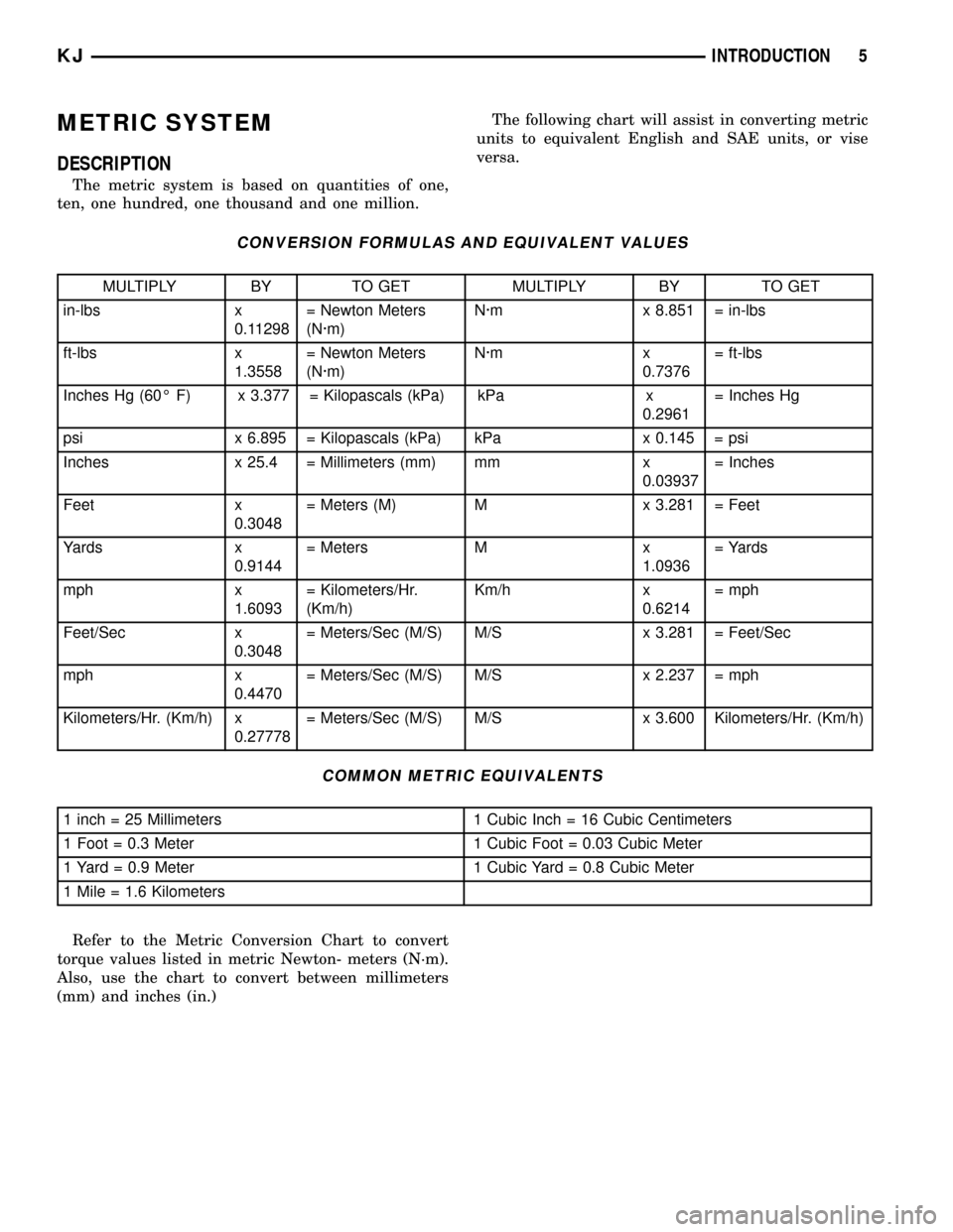
METRIC SYSTEM
DESCRIPTION
The metric system is based on quantities of one,
ten, one hundred, one thousand and one million.The following chart will assist in converting metric
units to equivalent English and SAE units, or vise
versa.
CONVERSION FORMULAS AND EQUIVALENT VALUES
MULTIPLY BY TO GET MULTIPLY BY TO GET
in-lbs x
0.11298= Newton Meters
(N´m)N´m x 8.851 = in-lbs
ft-lbs x
1.3558= Newton Meters
(N´m)N´m x
0.7376= ft-lbs
Inches Hg (60É F) x 3.377 = Kilopascals (kPa) kPa x
0.2961= Inches Hg
psi x 6.895 = Kilopascals (kPa) kPa x 0.145 = psi
Inches x 25.4 = Millimeters (mm) mm x
0.03937= Inches
Feet x
0.3048= Meters (M) M x 3.281 = Feet
Yards x
0.9144= Meters M x
1.0936= Yards
mph x
1.6093= Kilometers/Hr.
(Km/h)Km/h x
0.6214= mph
Feet/Sec x
0.3048= Meters/Sec (M/S) M/S x 3.281 = Feet/Sec
mph x
0.4470= Meters/Sec (M/S) M/S x 2.237 = mph
Kilometers/Hr. (Km/h) x
0.27778= Meters/Sec (M/S) M/S x 3.600 Kilometers/Hr. (Km/h)
COMMON METRIC EQUIVALENTS
1 inch = 25 Millimeters 1 Cubic Inch = 16 Cubic Centimeters
1 Foot = 0.3 Meter 1 Cubic Foot = 0.03 Cubic Meter
1 Yard = 0.9 Meter 1 Cubic Yard = 0.8 Cubic Meter
1 Mile = 1.6 Kilometers
Refer to the Metric Conversion Chart to convert
torque values listed in metric Newton- meters (N´m).
Also, use the chart to convert between millimeters
(mm) and inches (in.)
KJINTRODUCTION 5
Page 68 of 1803
FRONT AXLE - 186FIA
TABLE OF CONTENTS
page page
FRONT AXLE - 186FIA
DESCRIPTION.........................19
OPERATION...........................19
DIAGNOSIS AND TESTING - AXLE..........20
REMOVAL.............................24
INSTALLATION.........................24
ADJUSTMENTS........................25
SPECIFICATIONS - FRONT AXLE...........33
SPECIAL TOOLS
FRONT AXLE........................34
AXLE SHAFTS
REMOVAL.............................37
INSTALLATION.........................37
AXLE SHAFT SEALS
REMOVAL.............................37
INSTALLATION.........................38
AXLE BEARINGS
REMOVAL.............................38INSTALLATION.........................38
PINION SEAL
REMOVAL.............................38
INSTALLATION.........................39
DIFFERENTIAL
REMOVAL.............................40
DISASSEMBLY.........................41
ASSEMBLY............................41
INSTALLATION.........................42
DIFFERENTIAL CASE BEARINGS
REMOVAL.............................43
INSTALLATION.........................44
PINION GEAR/RING GEAR
REMOVAL.............................44
INSTALLATION.........................46
FRONT AXLE - 186FIA
DESCRIPTION
The 186FIA (Model 30) axle consists of an alumu-
num center section with an axle tube extending from
one side. The tube is pressed into the differential
housing. The integral type housing, hypoid gear
design has the centerline of the pinion set below the
centerline of the ring gear.
The differential case is a one-piece design. The differ-
ential pinion mate shaft is retained with a roll-pin. Dif-
ferential bearing preload and ring gear backlash is
adjusted by the use of shims (select thickness). The
shims are located between the differential bearing cups
and the axle housing. Pinion bearing preload is set and
maintained by the use of a collapsible spacer.
The power is transferred from the axle through two
constant velocity (C/V) drive shafts to the wheel hubs.
The differential cover provides a means for inspec-
tion and service without removing the axle from the
vehicle. The cover has a vent tube used to relieve
internal pressure caused by vaporization and inter-
nal expansion.
OPERATION
The axle receives power from the transfer case through
the front propeller shaft. The front propeller shaft is con-
nected to the pinion gear which rotates the differential
through the gear mesh with the ring gear bolted to thedifferential case. The engine power is transmitted to the
axle shafts through the pinion mate and side gears. The
side gears are splined to the axle shafts.
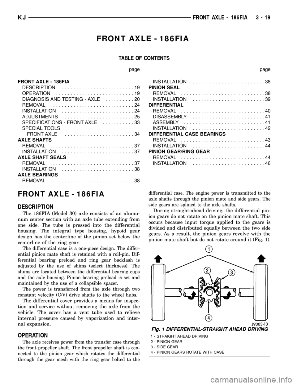
During straight-ahead driving, the differential pin-
ion gears do not rotate on the pinion mate shaft. This
occurs because input torque applied to the gears is
divided and distributed equally between the two side
gears. As a result, the pinion gears revolve with the
pinion mate shaft but do not rotate around it (Fig. 1).
Fig. 1 DIFFERENTIAL-STRAIGHT AHEAD DRIVING
1 - STRAIGHT AHEAD DRIVING
2 - PINION GEAR
3 - SIDE GEAR
4 - PINION GEARS ROTATE WITH CASE
KJFRONT AXLE - 186FIA 3 - 19
Page 75 of 1803
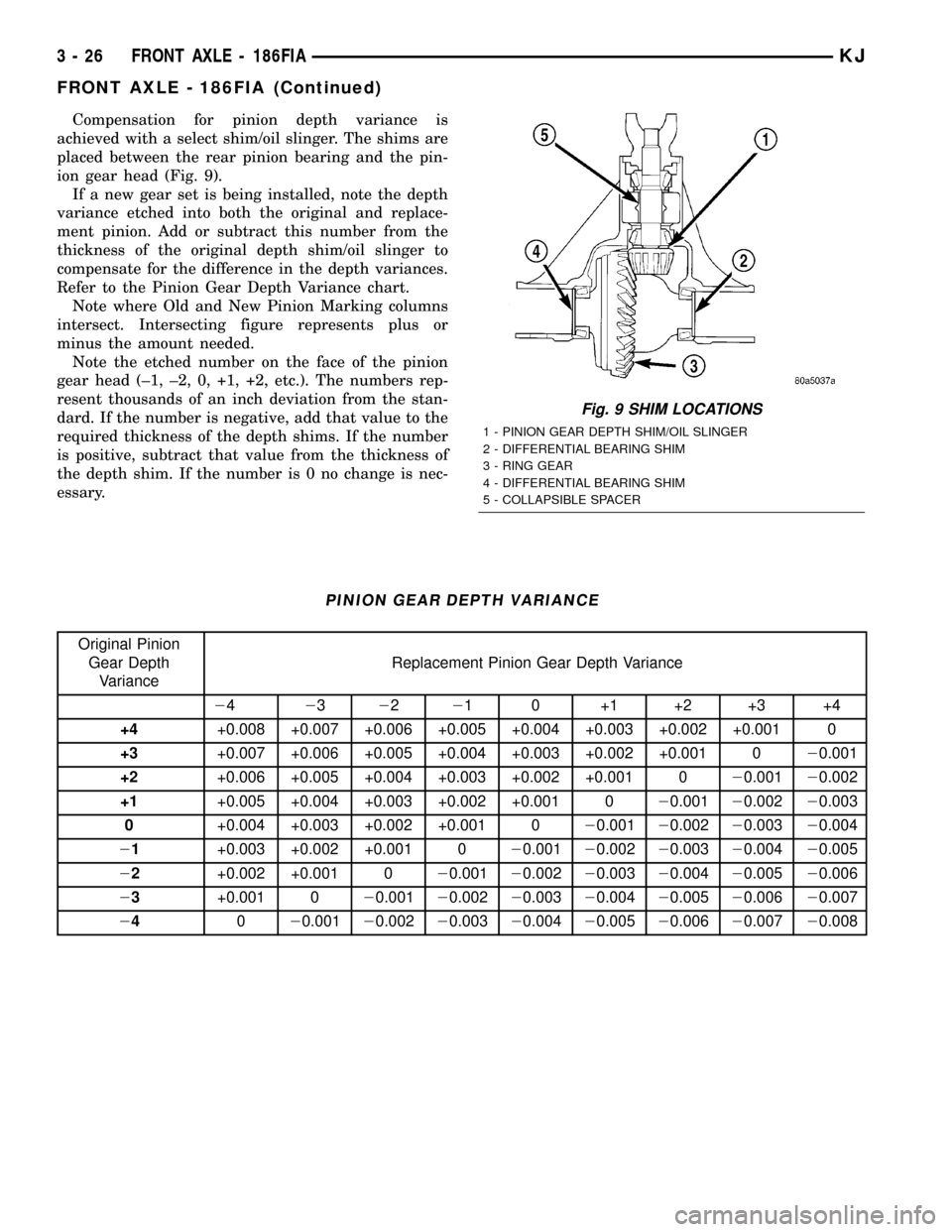
Compensation for pinion depth variance is
achieved with a select shim/oil slinger. The shims are
placed between the rear pinion bearing and the pin-
ion gear head (Fig. 9).
If a new gear set is being installed, note the depth
variance etched into both the original and replace-
ment pinion. Add or subtract this number from the
thickness of the original depth shim/oil slinger to
compensate for the difference in the depth variances.
Refer to the Pinion Gear Depth Variance chart.
Note where Old and New Pinion Marking columns
intersect. Intersecting figure represents plus or
minus the amount needed.
Note the etched number on the face of the pinion
gear head (±1, ±2, 0, +1, +2, etc.). The numbers rep-
resent thousands of an inch deviation from the stan-
dard. If the number is negative, add that value to the
required thickness of the depth shims. If the number
is positive, subtract that value from the thickness of
the depth shim. If the number is 0 no change is nec-
essary.
PINION GEAR DEPTH VARIANCE
Original Pinion
Gear Depth
VarianceReplacement Pinion Gear Depth Variance
24232221 0 +1 +2 +3 +4
+4+0.008 +0.007 +0.006 +0.005 +0.004 +0.003 +0.002 +0.001 0
+3+0.007 +0.006 +0.005 +0.004 +0.003 +0.002 +0.001 020.001
+2+0.006 +0.005 +0.004 +0.003 +0.002 +0.001 020.00120.002
+1+0.005 +0.004 +0.003 +0.002 +0.001 020.00120.00220.003
0+0.004 +0.003 +0.002 +0.001 020.00120.00220.00320.004
21+0.003 +0.002 +0.001 020.00120.00220.00320.00420.005
22+0.002 +0.001 020.00120.00220.00320.00420.00520.006
23+0.001 020.00120.00220.00320.00420.00520.00620.007
24020.00120.00220.00320.00420.00520.00620.00720.008
Fig. 9 SHIM LOCATIONS
1 - PINION GEAR DEPTH SHIM/OIL SLINGER
2 - DIFFERENTIAL BEARING SHIM
3 - RING GEAR
4 - DIFFERENTIAL BEARING SHIM
5 - COLLAPSIBLE SPACER
3 - 26 FRONT AXLE - 186FIAKJ
FRONT AXLE - 186FIA (Continued)
Page 77 of 1803
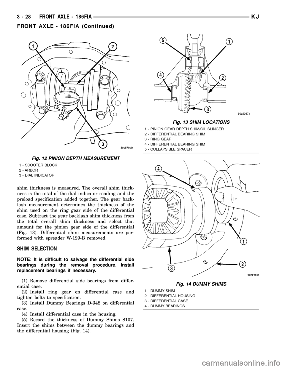
shim thickness is measured. The overall shim thick-
ness is the total of the dial indicator reading and the
preload specification added together. The gear back-
lash measurement determines the thickness of the
shim used on the ring gear side of the differential
case. Subtract the gear backlash shim thickness from
the total overall shim thickness and select that
amount for the pinion gear side of the differential
(Fig. 13). Differential shim measurements are per-
formed with spreader W-129-B removed.
SHIM SELECTION
NOTE: It is difficult to salvage the differential side
bearings during the removal procedure. Install
replacement bearings if necessary.
(1) Remove differential side bearings from differ-
ential case.
(2) Install ring gear on differential case and
tighten bolts to specification.
(3) Install Dummy Bearings D-348 on differential
case.
(4) Install differential case in the housing.
(5) Record the thickness of Dummy Shims 8107.
Insert the shims between the dummy bearings and
the differential housing (Fig. 14).
Fig. 12 PINION DEPTH MEASUREMENT
1 - SCOOTER BLOCK
2 - ARBOR
3 - DIAL INDICATOR
Fig. 13 SHIM LOCATIONS
1 - PINION GEAR DEPTH SHIM/OIL SLINGER
2 - DIFFERENTIAL BEARING SHIM
3 - RING GEAR
4 - DIFFERENTIAL BEARING SHIM
5 - COLLAPSIBLE SPACER
Fig. 14 DUMMY SHIMS
1 - DUMMY SHIM
2 - DIFFERENTIAL HOUSING
3 - DIFFERENTIAL CASE
4 - DUMMY BEARINGS
3 - 28 FRONT AXLE - 186FIAKJ
FRONT AXLE - 186FIA (Continued)
Page 88 of 1803
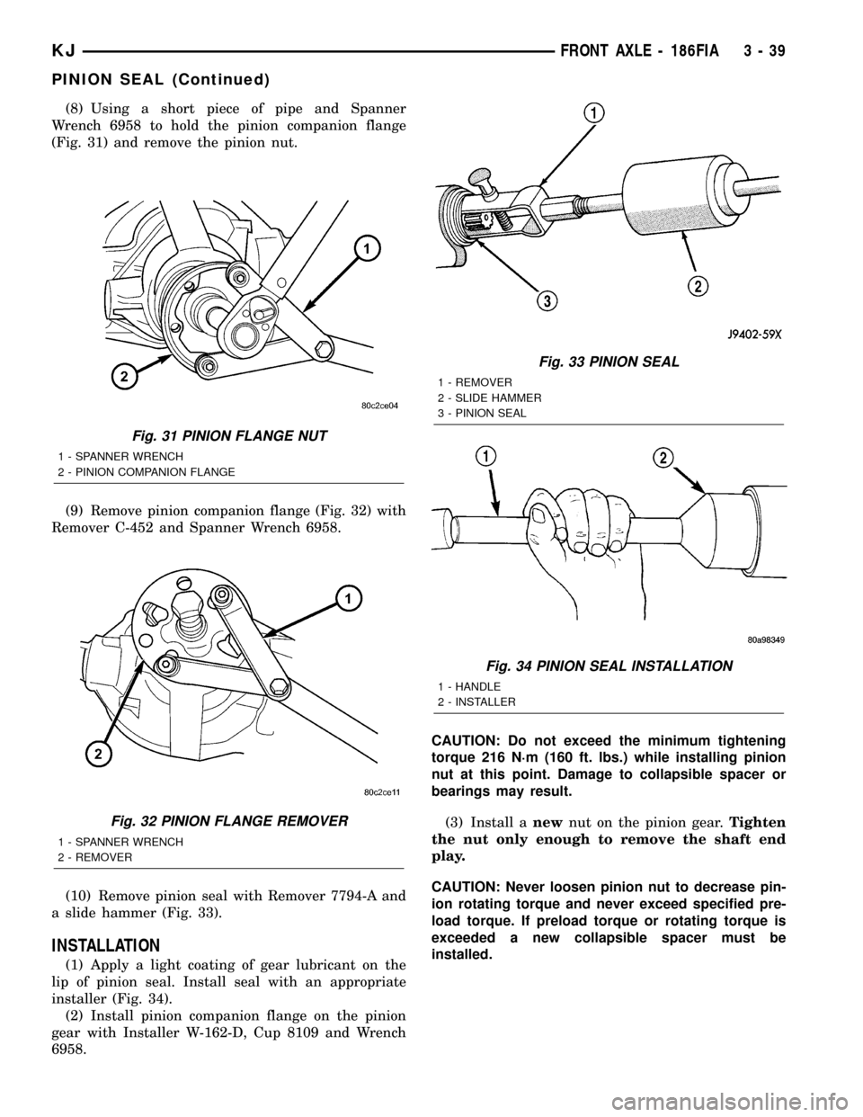
(8) Using a short piece of pipe and Spanner
Wrench 6958 to hold the pinion companion flange
(Fig. 31) and remove the pinion nut.
(9) Remove pinion companion flange (Fig. 32) with
Remover C-452 and Spanner Wrench 6958.
(10) Remove pinion seal with Remover 7794-A and
a slide hammer (Fig. 33).
INSTALLATION
(1) Apply a light coating of gear lubricant on the
lip of pinion seal. Install seal with an appropriate
installer (Fig. 34).
(2) Install pinion companion flange on the pinion
gear with Installer W-162-D, Cup 8109 and Wrench
6958.CAUTION: Do not exceed the minimum tightening
torque 216 N´m (160 ft. lbs.) while installing pinion
nut at this point. Damage to collapsible spacer or
bearings may result.
(3) Install anewnut on the pinion gear.Tighten
the nut only enough to remove the shaft end
play.
CAUTION: Never loosen pinion nut to decrease pin-
ion rotating torque and never exceed specified pre-
load torque. If preload torque or rotating torque is
exceeded a new collapsible spacer must be
installed.
Fig. 31 PINION FLANGE NUT
1 - SPANNER WRENCH
2 - PINION COMPANION FLANGE
Fig. 32 PINION FLANGE REMOVER
1 - SPANNER WRENCH
2 - REMOVER
Fig. 33 PINION SEAL
1 - REMOVER
2 - SLIDE HAMMER
3 - PINION SEAL
Fig. 34 PINION SEAL INSTALLATION
1 - HANDLE
2 - INSTALLER
KJFRONT AXLE - 186FIA 3 - 39
PINION SEAL (Continued)
Page 89 of 1803
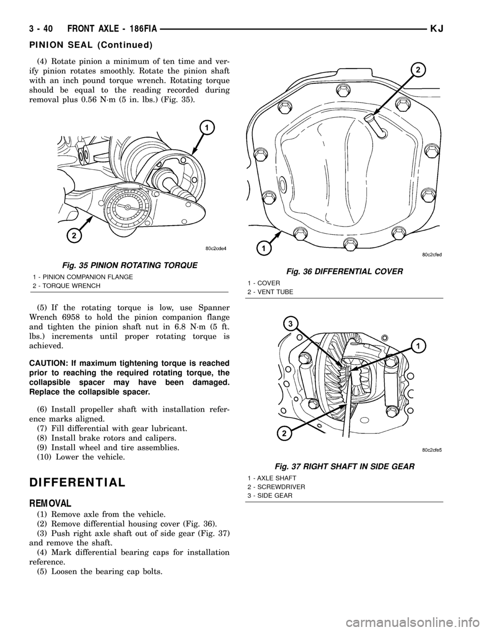
(4) Rotate pinion a minimum of ten time and ver-
ify pinion rotates smoothly. Rotate the pinion shaft
with an inch pound torque wrench. Rotating torque
should be equal to the reading recorded during
removal plus 0.56 N´m (5 in. lbs.) (Fig. 35).
(5) If the rotating torque is low, use Spanner
Wrench 6958 to hold the pinion companion flange
and tighten the pinion shaft nut in 6.8 N´m (5 ft.
lbs.) increments until proper rotating torque is
achieved.
CAUTION: If maximum tightening torque is reached
prior to reaching the required rotating torque, the
collapsible spacer may have been damaged.
Replace the collapsible spacer.
(6) Install propeller shaft with installation refer-
ence marks aligned.
(7) Fill differential with gear lubricant.
(8) Install brake rotors and calipers.
(9) Install wheel and tire assemblies.
(10) Lower the vehicle.
DIFFERENTIAL
REMOVAL
(1) Remove axle from the vehicle.
(2) Remove differential housing cover (Fig. 36).
(3) Push right axle shaft out of side gear (Fig. 37)
and remove the shaft.
(4) Mark differential bearing caps for installation
reference.
(5) Loosen the bearing cap bolts.
Fig. 35 PINION ROTATING TORQUE
1 - PINION COMPANION FLANGE
2 - TORQUE WRENCHFig. 36 DIFFERENTIAL COVER
1 - COVER
2 - VENT TUBE
Fig. 37 RIGHT SHAFT IN SIDE GEAR
1 - AXLE SHAFT
2 - SCREWDRIVER
3 - SIDE GEAR
3 - 40 FRONT AXLE - 186FIAKJ
PINION SEAL (Continued)
Page 94 of 1803
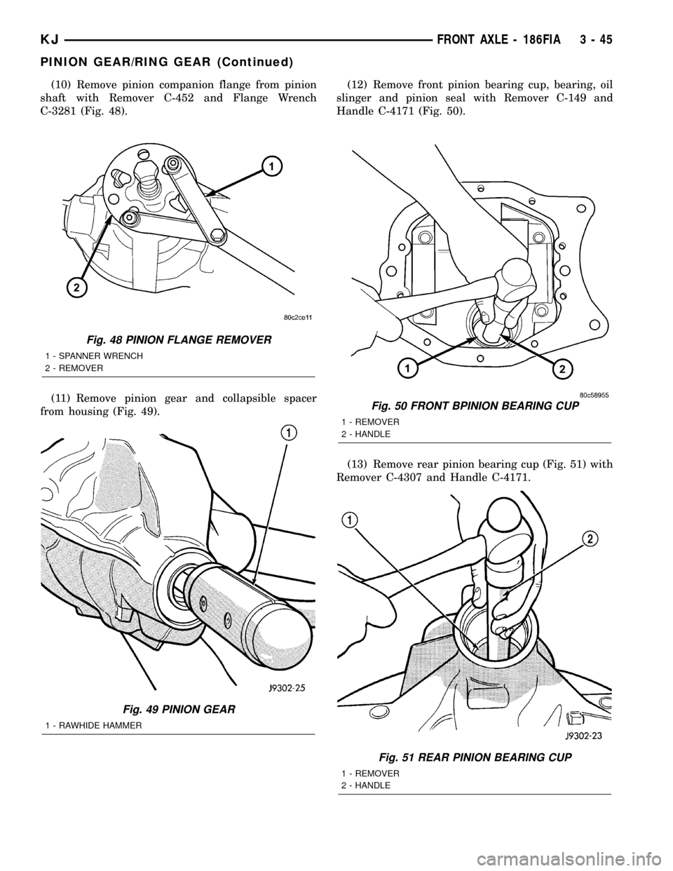
(10) Remove pinion companion flange from pinion
shaft with Remover C-452 and Flange Wrench
C-3281 (Fig. 48).
(11) Remove pinion gear and collapsible spacer
from housing (Fig. 49).(12) Remove front pinion bearing cup, bearing, oil
slinger and pinion seal with Remover C-149 and
Handle C-4171 (Fig. 50).
(13) Remove rear pinion bearing cup (Fig. 51) with
Remover C-4307 and Handle C-4171.
Fig. 48 PINION FLANGE REMOVER
1 - SPANNER WRENCH
2 - REMOVER
Fig. 49 PINION GEAR
1 - RAWHIDE HAMMER
Fig. 50 FRONT BPINION BEARING CUP
1 - REMOVER
2 - HANDLE
Fig. 51 REAR PINION BEARING CUP
1 - REMOVER
2 - HANDLE
KJFRONT AXLE - 186FIA 3 - 45
PINION GEAR/RING GEAR (Continued)
Page 95 of 1803
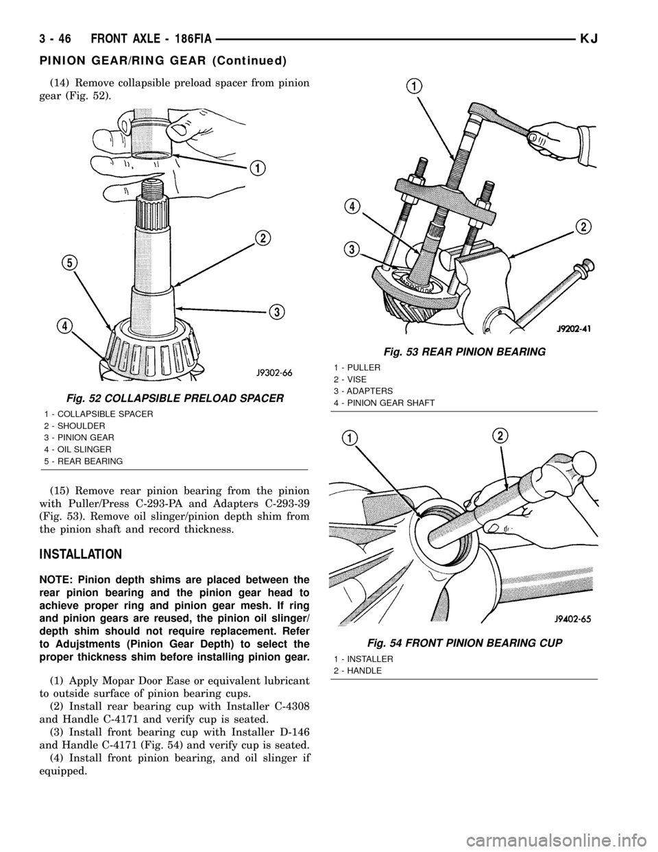
(14) Remove collapsible preload spacer from pinion
gear (Fig. 52).
(15) Remove rear pinion bearing from the pinion
with Puller/Press C-293-PA and Adapters C-293-39
(Fig. 53). Remove oil slinger/pinion depth shim from
the pinion shaft and record thickness.
INSTALLATION
NOTE: Pinion depth shims are placed between the
rear pinion bearing and the pinion gear head to
achieve proper ring and pinion gear mesh. If ring
and pinion gears are reused, the pinion oil slinger/
depth shim should not require replacement. Refer
to Adujstments (Pinion Gear Depth) to select the
proper thickness shim before installing pinion gear.
(1) Apply Mopar Door Ease or equivalent lubricant
to outside surface of pinion bearing cups.
(2) Install rear bearing cup with Installer C-4308
and Handle C-4171 and verify cup is seated.
(3) Install front bearing cup with Installer D-146
and Handle C-4171 (Fig. 54) and verify cup is seated.
(4) Install front pinion bearing, and oil slinger if
equipped.
Fig. 52 COLLAPSIBLE PRELOAD SPACER
1 - COLLAPSIBLE SPACER
2 - SHOULDER
3 - PINION GEAR
4 - OIL SLINGER
5 - REAR BEARING
Fig. 53 REAR PINION BEARING
1 - PULLER
2 - VISE
3 - ADAPTERS
4 - PINION GEAR SHAFT
Fig. 54 FRONT PINION BEARING CUP
1 - INSTALLER
2 - HANDLE
3 - 46 FRONT AXLE - 186FIAKJ
PINION GEAR/RING GEAR (Continued)
Page 96 of 1803
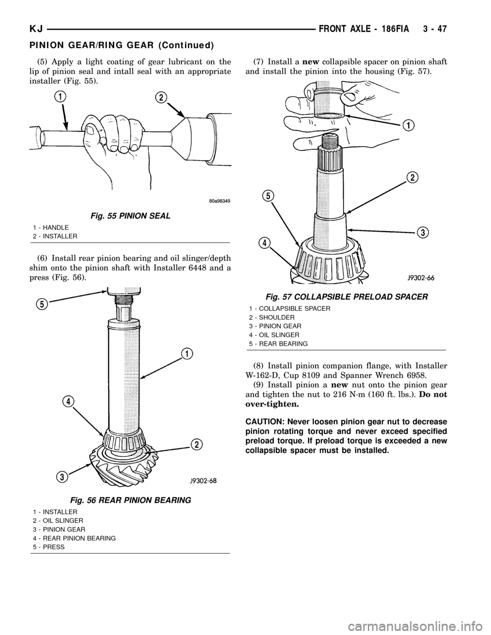
(5) Apply a light coating of gear lubricant on the
lip of pinion seal and intall seal with an appropriate
installer (Fig. 55).
(6) Install rear pinion bearing and oil slinger/depth
shim onto the pinion shaft with Installer 6448 and a
press (Fig. 56).(7) Install anewcollapsible spacer on pinion shaft
and install the pinion into the housing (Fig. 57).
(8) Install pinion companion flange, with Installer
W-162-D, Cup 8109 and Spanner Wrench 6958.
(9) Install pinion anewnut onto the pinion gear
and tighten the nut to 216 N´m (160 ft. lbs.).Do not
over-tighten.
CAUTION: Never loosen pinion gear nut to decrease
pinion rotating torque and never exceed specified
preload torque. If preload torque is exceeded a new
collapsible spacer must be installed.
Fig. 55 PINION SEAL
1 - HANDLE
2 - INSTALLER
Fig. 56 REAR PINION BEARING
1 - INSTALLER
2 - OIL SLINGER
3 - PINION GEAR
4 - REAR PINION BEARING
5 - PRESS
Fig. 57 COLLAPSIBLE PRELOAD SPACER
1 - COLLAPSIBLE SPACER
2 - SHOULDER
3 - PINION GEAR
4 - OIL SLINGER
5 - REAR BEARING
KJFRONT AXLE - 186FIA 3 - 47
PINION GEAR/RING GEAR (Continued)
Page 97 of 1803
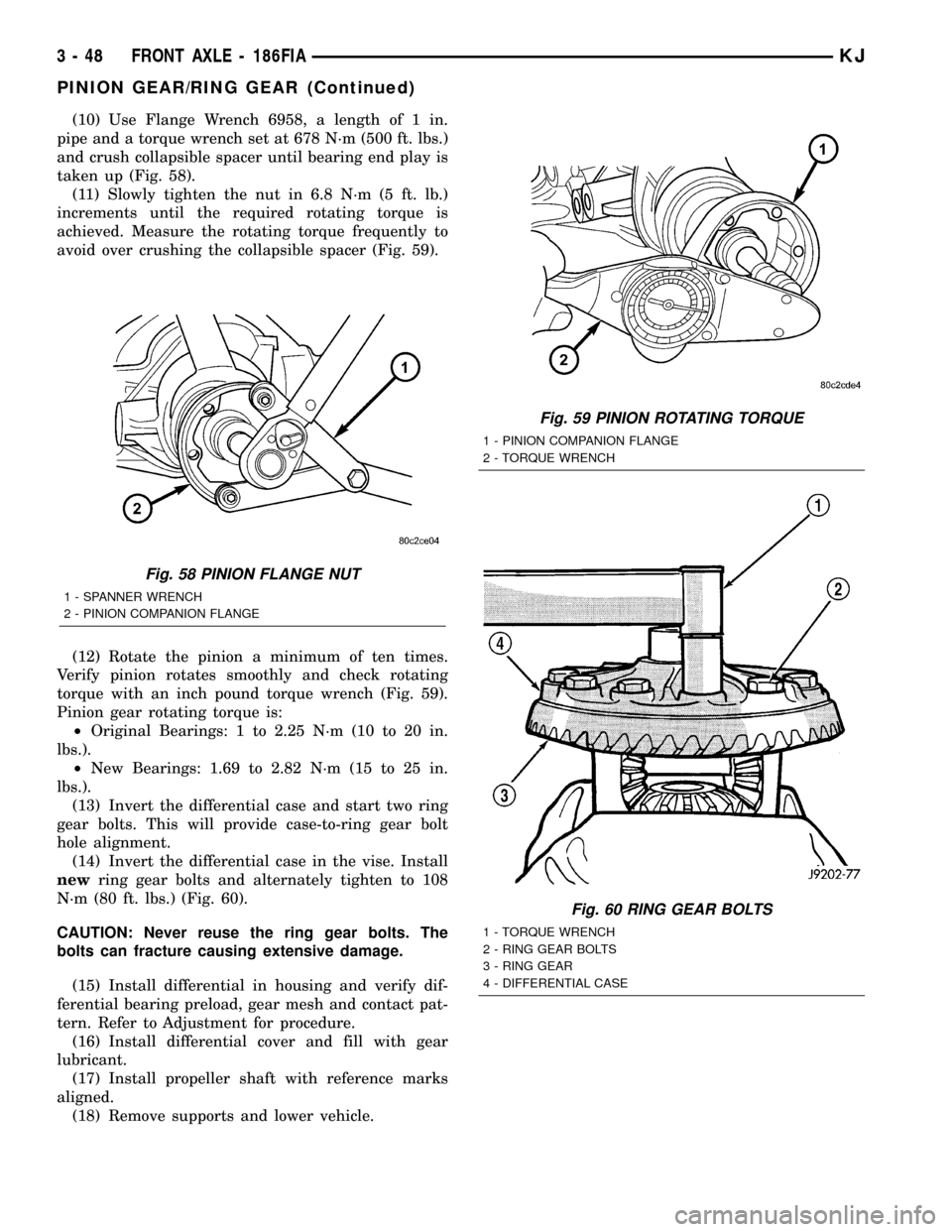
(10) Use Flange Wrench 6958, a length of 1 in.
pipe and a torque wrench set at 678 N´m (500 ft. lbs.)
and crush collapsible spacer until bearing end play is
taken up (Fig. 58).
(11) Slowly tighten the nut in 6.8 N´m (5 ft. lb.)
increments until the required rotating torque is
achieved. Measure the rotating torque frequently to
avoid over crushing the collapsible spacer (Fig. 59).
(12) Rotate the pinion a minimum of ten times.
Verify pinion rotates smoothly and check rotating
torque with an inch pound torque wrench (Fig. 59).
Pinion gear rotating torque is:
²Original Bearings: 1 to 2.25 N´m (10 to 20 in.
lbs.).
²New Bearings: 1.69 to 2.82 N´m (15 to 25 in.
lbs.).
(13) Invert the differential case and start two ring
gear bolts. This will provide case-to-ring gear bolt
hole alignment.
(14) Invert the differential case in the vise. Install
newring gear bolts and alternately tighten to 108
N´m (80 ft. lbs.) (Fig. 60).
CAUTION: Never reuse the ring gear bolts. The
bolts can fracture causing extensive damage.
(15) Install differential in housing and verify dif-
ferential bearing preload, gear mesh and contact pat-
tern. Refer to Adjustment for procedure.
(16) Install differential cover and fill with gear
lubricant.
(17) Install propeller shaft with reference marks
aligned.
(18) Remove supports and lower vehicle.
Fig. 58 PINION FLANGE NUT
1 - SPANNER WRENCH
2 - PINION COMPANION FLANGE
Fig. 59 PINION ROTATING TORQUE
1 - PINION COMPANION FLANGE
2 - TORQUE WRENCH
Fig. 60 RING GEAR BOLTS
1 - TORQUE WRENCH
2 - RING GEAR BOLTS
3 - RING GEAR
4 - DIFFERENTIAL CASE
3 - 48 FRONT AXLE - 186FIAKJ
PINION GEAR/RING GEAR (Continued)