Psi JEEP LIBERTY 2002 KJ / 1.G Owner's Manual
[x] Cancel search | Manufacturer: JEEP, Model Year: 2002, Model line: LIBERTY, Model: JEEP LIBERTY 2002 KJ / 1.GPages: 1803, PDF Size: 62.3 MB
Page 135 of 1803
REAR AXLE-81/4
TABLE OF CONTENTS
page page
REAR AXLE-81/4
DESCRIPTION.........................86
OPERATION...........................86
DIAGNOSIS AND TESTING - AXLE..........88
REMOVAL.............................91
INSTALLATION.........................91
ADJUSTMENTS........................92
SPECIFICATIONS
REAR AXLE..........................98
SPECIAL TOOLS
8 1/4 AXLE..........................98
AXLE SHAFTS
REMOVAL............................101
INSTALLATION........................101
AXLE SHAFT SEALS
REMOVAL............................101
INSTALLATION........................102
AXLE BEARINGS
REMOVAL............................102
INSTALLATION........................102PINION SEAL
REMOVAL............................102
INSTALLATION........................103
DIFFERENTIAL
REMOVAL............................104
DISASSEMBLY........................105
ASSEMBLY...........................105
INSTALLATION........................105
DIFFERENTIAL - TRAC-LOK
DIAGNOSIS AND TESTING - TRAC-LOKT....106
DISASSEMBLY........................107
CLEANING...........................109
INSPECTION.........................109
ASSEMBLY...........................109
DIFFERENTIAL CASE BEARINGS
REMOVAL............................110
INSTALLATION........................110
PINION GEAR/RING GEAR/TONE RING
REMOVAL............................110
INSTALLATION........................112
REAR AXLE-81/4
DESCRIPTION
The axle housings consist of a cast iron center sec-
tion with axle tubes extending from either side. The
tubes are pressed into and welded to the differential
housing to form a one-piece axle housing. The axles
are equipped with semi-floating axle shafts, meaning
vehicle loads are supported by the axle shaft and
bearings. The axle shafts are retained by C-locks in
the differential side gears.
The differential case is a one-piece design. The dif-
ferential pinion mate shaft is retained with a
threaded pin. Differential bearing preload and ring
gear backlash are set and maintained by threaded
adjusters at the outside of the differential housing.
Pinion bearing preload is set and maintained by the
use of a collapsible spacer.
The differential cover provides a means for inspec-
tion and service without removing the complete axlefrom the vehicle. A vent hose is used to relieve inter-
nal pressure caused by lubricant vaporization and
internal expansion.
Axles equipped with a Trac-Loktdifferential are
optional. A differential has a one-piece differential
case, and the same internal components as a stan-
dard differential, plus two clutch disc packs.
OPERATION
The axle receives power from the transmission/
transfer case through the rear propeller shaft. The
rear propeller shaft is connected to the pinion gear
which rotates the differential through the gear mesh
with the ring gear bolted to the differential case. The
engine power is transmitted to the axle shafts
through the pinion mate and side gears. The side
gears are splined to the axle shafts.
3 - 86 REAR AXLE-81/4KJ
Page 141 of 1803
(10) Install axle vent hose.
(11) Install propeller shaft with reference marks.
(12) Install the wheels and tires.
(13) Add gear lubricant to specifications, if neces-
sary.
(14) Remove lifting device from axle and lower the
vehicle.
(15) Tighten the lower control arm bolts to torque
specification.
ADJUSTMENTS
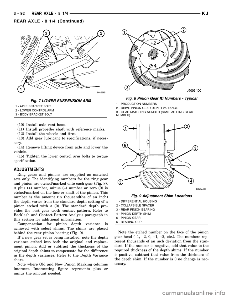
Ring gears and pinions are supplied as matched
sets only. The identifying numbers for the ring gear
and pinion are etched/marked onto each gear (Fig. 8).
A plus (+) number, minus (±) number or zero (0) is
etched/marked on the face or shaft of the pinion. This
number is the amount (in thousandths of an inch)
the depth varies from the standard depth setting of a
pinion etched with a (0). The standard depth pro-
vides the best gear tooth contact pattern. Refer to
Backlash and Contact Pattern Analysis paragraph in
this section for additional information.
Compensation for pinion depth variance is
achieved with select shims. The shims are placed
behind the rear pinion bearing (Fig. 9).
If a new gear set is being installed, note the depth
variance etched into both the original and replace-
ment pinion. Add or subtract the thickness of the
original depth shims to compensate for the difference
in the depth variances. Refer to the Depth Variance
chart.
Note where Old and New Pinion Marking columns
intersect. Intersecting figure represents plus or
minus the amount needed.Note the etched number on the face of the pinion
gear head (±1, ±2, 0, +1, +2, etc.). The numbers rep-
resent thousands of an inch deviation from the stan-
dard. If the number is negative, add that value to the
required thickness of the depth shims. If the number
is positive, subtract that value from the thickness of
the depth shim. If the number is 0 no change is nec-
essary.
Fig. 7 LOWER SUSPENSION ARM
1 - AXLE BRACKET BOLT
2 - LOWER CONTROL ARM
3 - BODY BRACKET BOLT
Fig. 8 Pinion Gear ID Numbers - Typical
1 - PRODUCTION NUMBERS
2 - DRIVE PINION GEAR DEPTH VARIANCE
3 - GEAR MATCHING NUMBER (SAME AS RING GEAR
NUMBER)
Fig. 9 Adjustment Shim Locations
1 - DIFFERENTIAL HOUSING
2 - COLLAPSIBLE SPACER
3 - REAR PINION BEARING
4 - PINION DEPTH SHIM
5 - PINION GEAR
6 - BEARING CUP
3 - 92 REAR AXLE-81/4KJ
REAR AXLE - 8 1/4 (Continued)
Page 152 of 1803
(7) Measure rotating torque of the pinion gear
with an inch pound torque wrench and record the
reading for installation reference.
(8) Hold the pinion yoke with Holder 6719 and
remove the pinion nut and washer.
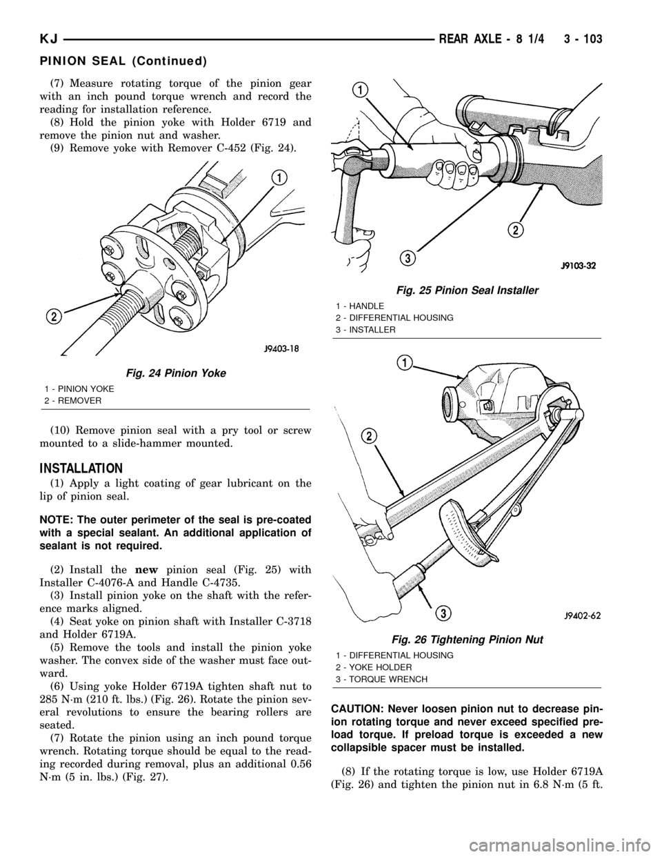
(9) Remove yoke with Remover C-452 (Fig. 24).
(10) Remove pinion seal with a pry tool or screw
mounted to a slide-hammer mounted.
INSTALLATION
(1) Apply a light coating of gear lubricant on the
lip of pinion seal.
NOTE: The outer perimeter of the seal is pre-coated
with a special sealant. An additional application of
sealant is not required.
(2) Install thenewpinion seal (Fig. 25) with
Installer C-4076-A and Handle C-4735.
(3) Install pinion yoke on the shaft with the refer-
ence marks aligned.
(4) Seat yoke on pinion shaft with Installer C-3718
and Holder 6719A.
(5) Remove the tools and install the pinion yoke
washer. The convex side of the washer must face out-
ward.
(6) Using yoke Holder 6719A tighten shaft nut to
285 N´m (210 ft. lbs.) (Fig. 26). Rotate the pinion sev-
eral revolutions to ensure the bearing rollers are
seated.
(7) Rotate the pinion using an inch pound torque
wrench. Rotating torque should be equal to the read-
ing recorded during removal, plus an additional 0.56
N´m (5 in. lbs.) (Fig. 27).CAUTION: Never loosen pinion nut to decrease pin-
ion rotating torque and never exceed specified pre-
load torque. If preload torque is exceeded a new
collapsible spacer must be installed.
(8) If the rotating torque is low, use Holder 6719A
(Fig. 26) and tighten the pinion nut in 6.8 N´m (5 ft.
Fig. 24 Pinion Yoke
1 - PINION YOKE
2 - REMOVER
Fig. 25 Pinion Seal Installer
1 - HANDLE
2 - DIFFERENTIAL HOUSING
3 - INSTALLER
Fig. 26 Tightening Pinion Nut
1 - DIFFERENTIAL HOUSING
2 - YOKE HOLDER
3 - TORQUE WRENCH
KJREAR AXLE - 8 1/4 3 - 103
PINION SEAL (Continued)
Page 161 of 1803
(10) Remove pinion shaft seal with a pry tool or
slide-hammer mounted screw.
(11) Remove oil slinger, if equipped, and front pin-
ion bearing.
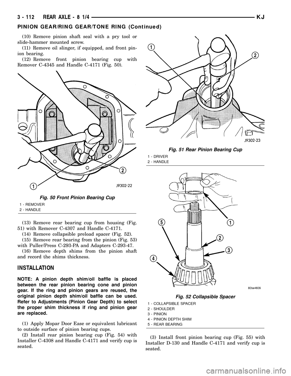
(12) Remove front pinion bearing cup with
Remover C-4345 and Handle C-4171 (Fig. 50).
(13) Remove rear bearing cup from housing (Fig.
51) with Remover C-4307 and Handle C-4171.
(14) Remove collapsible preload spacer (Fig. 52).
(15) Remove rear bearing from the pinion (Fig. 53)
with Puller/Press C-293-PA and Adapters C-293-47.
(16) Remove depth shims from the pinion shaft
and record the shims thickness.
INSTALLATION
NOTE: A pinion depth shim/oil baffle is placed
between the rear pinion bearing cone and pinion
gear. If the ring and pinion gears are reused, the
original pinion depth shim/oil baffle can be used.
Refer to Adjustments (Pinion Gear Depth) to select
the proper shim thickness if ring and pinion gear
are replaced.
(1) Apply Mopar Door Ease or equivalent lubricant
to outside surface of pinion bearing cups.
(2) Install rear pinion bearing cup (Fig. 54) with
Installer C-4308 and Handle C-4171 and verify cup is
seated.(3) Install front pinion bearing cup (Fig. 55) with
Installer D-130 and Handle C-4171 and verify cup is
seated.
Fig. 50 Front Pinion Bearing Cup
1 - REMOVER
2 - HANDLE
Fig. 51 Rear Pinion Bearing Cup
1 - DRIVER
2 - HANDLE
Fig. 52 Collapsible Spacer
1 - COLLAPSIBLE SPACER
2 - SHOULDER
3 - PINION
4 - PINION DEPTH SHIM
5 - REAR BEARING
3 - 112 REAR AXLE-81/4KJ
PINION GEAR/RING GEAR/TONE RING (Continued)
Page 162 of 1803
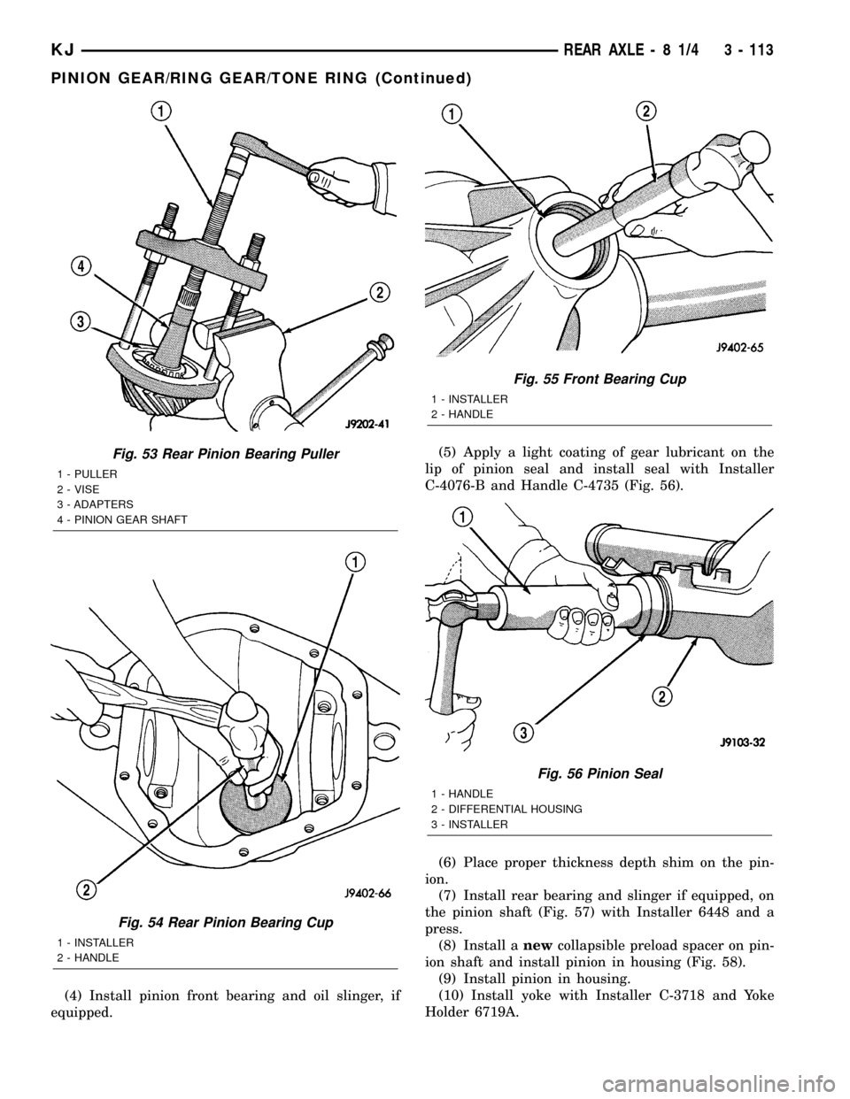
(4) Install pinion front bearing and oil slinger, if
equipped.(5) Apply a light coating of gear lubricant on the
lip of pinion seal and install seal with Installer
C-4076-B and Handle C-4735 (Fig. 56).
(6) Place proper thickness depth shim on the pin-
ion.
(7) Install rear bearing and slinger if equipped, on
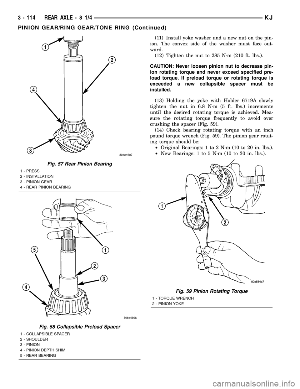
the pinion shaft (Fig. 57) with Installer 6448 and a
press.
(8) Install anewcollapsible preload spacer on pin-
ion shaft and install pinion in housing (Fig. 58).
(9) Install pinion in housing.
(10) Install yoke with Installer C-3718 and Yoke
Holder 6719A.
Fig. 53 Rear Pinion Bearing Puller
1 - PULLER
2 - VISE
3 - ADAPTERS
4 - PINION GEAR SHAFT
Fig. 54 Rear Pinion Bearing Cup
1 - INSTALLER
2 - HANDLE
Fig. 55 Front Bearing Cup
1 - INSTALLER
2 - HANDLE
Fig. 56 Pinion Seal
1 - HANDLE
2 - DIFFERENTIAL HOUSING
3 - INSTALLER
KJREAR AXLE - 8 1/4 3 - 113
PINION GEAR/RING GEAR/TONE RING (Continued)
Page 163 of 1803
(11) Install yoke washer and a new nut on the pin-
ion. The convex side of the washer must face out-
ward.
(12) Tighten the nut to 285 N´m (210 ft. lbs.).
CAUTION: Never loosen pinion nut to decrease pin-
ion rotating torque and never exceed specified pre-
load torque. If preload torque or rotating torque is
exceeded a new collapsible spacer must be
installed.
(13) Holding the yoke with Holder 6719A slowly
tighten the nut in 6.8 N´m (5 ft. lbs.) increments
until the desired rotating torque is achieved. Mea-
sure the rotating torque frequently to avoid over
crushing the spacer (Fig. 59).
(14) Check bearing rotating torque with an inch
pound torque wrench (Fig. 59). The pinion gear rotat-
ing torque should be:
²Original Bearings: 1 to 2 N´m (10 to 20 in. lbs.).
²New Bearings: 1 to 5 N´m (10 to 30 in. lbs.).
Fig. 57 Rear Pinion Bearing
1 - PRESS
2 - INSTALLATION
3 - PINION GEAR
4 - REAR PINION BEARING
Fig. 58 Collapsible Preload Spacer
1 - COLLAPSIBLE SPACER
2 - SHOULDER
3 - PINION
4 - PINION DEPTH SHIM
5 - REAR BEARING
Fig. 59 Pinion Rotating Torque
1 - TORQUE WRENCH
2 - PINION YOKE
3 - 114 REAR AXLE-81/4KJ
PINION GEAR/RING GEAR/TONE RING (Continued)
Page 169 of 1803
BRAKES DO NOT HOLD AFTER DRIVING THROUGH DEEP
WATER PUDDLES
This condition is generally caused by water soaked
lining. If the lining is only wet, it can be dried by
driving with the brakes very lightly applied for a
mile or two. However, if the lining is both soaked and
dirt contaminated, cleaning and/or replacement will
be necessary.
BRAKE LINING CONTAMINATION
Brake lining contamination is mostly a product of
leaking calipers or wheel cylinders, worn seals, driv-
ing through deep water puddles, or lining that has
become covered with grease and grit during repair.
Contaminated lining should be replaced to avoid fur-
ther brake problems.
WHEEL AND TIRE PROBLEMS
Some conditions attributed to brake components
may actually be caused by a wheel or tire problem.
A damaged wheel can cause shudder, vibration and
pull. A worn or damaged tire can also cause pull.
Severely worn tires with very little tread left can
produce a grab-like condition as the tire loses and
recovers traction. Flat-spotted tires can cause vibra-
tion and generate shudder during brake operation. A
tire with internal damage such as a severe bruise,
cut, or ply separation can cause pull and vibration.
BRAKE NOISES
Some brake noise is common with rear drum
brakes and on some disc brakes during the first few
stops after a vehicle has been parked overnight or
stored. This is primarily due to the formation of trace
corrosion (light rust) on metal surfaces. This light
corrosion is typically cleared from the metal surfaces
after a few brake applications causing the noise to
subside.
BRAKE SQUEAK/SQUEAL
Brake squeak or squeal may be due to linings that
are wet or contaminated with brake fluid, grease, or
oil. Glazed linings and rotors with hard spots can
also contribute to squeak. Dirt and foreign material
embedded in the brake lining will also cause squeak/
squeal.
A very loud squeak or squeal is frequently a sign of
severely worn brake lining. If the lining has worn
through to the brake shoes in spots, metal-to-metal
contact occurs. If the condition is allowed to continue,
rotors and drums can become so scored that replace-
ment is necessary.
BRAKE CHATTER
Brake chatter is usually caused by loose or worn
components, or glazed/burnt lining. Rotors with hard
spots can also contribute to chatter. Additional causesof chatter are out-of-tolerance rotors, brake lining not
securely attached to the shoes, loose wheel bearings
and contaminated brake lining.
THUMP/CLUNK NOISE
Thumping or clunk noises during braking are fre-
quentlynotcaused by brake components. In many
cases, such noises are caused by loose or damaged
steering, suspension, or engine components. However,
calipers that bind on the slide surfaces can generate
a thump or clunk noise. In addition, worn out,
improperly adjusted, or improperly assembled rear
brake shoes can also produce a thump noise.
STANDARD PROCEDURE
STANDARD PROCEDURE - PRESSURE
BLEEDING
Use Mopar brake fluid, or an equivalent quality
fluid meeting SAE J1703-F and DOT 3 standards
only. Use fresh, clean fluid from a sealed container at
all times.
Do not pump the brake pedal at any time while
bleeding. Air in the system will be compressed into
small bubbles that are distributed throughout the
hydraulic system. This will make additional bleeding
operations necessary.
Do not allow the master cylinder to run out of fluid
during bleed operations. An empty cylinder will allow
additional air to be drawn into the system. Check the
cylinder fluid level frequently and add fluid as
needed.
Bleed only one brake component at a time in the
following sequence:
²Master Cylinder
²Combination Valve
²Right Rear Wheel
²Left Rear Wheel
²Right Front Wheel
²Left Front Wheel
Follow the manufacturers instructions carefully
when using pressure equipment. Do not exceed the
tank manufacturers pressure recommendations. Gen-
erally, a tank pressure of 15-20 psi is sufficient for
bleeding.
Fill the bleeder tank with recommended fluid and
purge air from the tank lines before bleeding.
Do not pressure bleed without a proper master cyl-
inder adapter. The wrong adapter can lead to leak-
age, or drawing air back into the system. Use
adapter provided with the equipment or Adapter
6921.
KJBRAKES - BASE 5 - 5
BRAKES - BASE (Continued)
Page 219 of 1803
DIAGNOSIS AND TESTING - COOLING SYSTEM
LEAKS
ULTRAVIOLET LIGHT METHOD
A leak detection additive is available through the
parts department that can be added to cooling sys-
tem. The additive is highly visible under ultraviolet
light (black light). Pour one ounce of additive into
cooling system. Place heater control unit in HEAT
position. Start and operate engine until radiator
upper hose is warm to touch. Aim the commercially
available black light tool at components to be
checked. If leaks are present, black light will cause
additive to glow a bright green color.
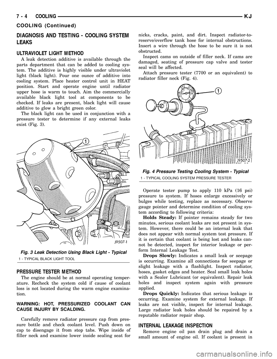
The black light can be used in conjunction with a
pressure tester to determine if any external leaks
exist (Fig. 3).
PRESSURE TESTER METHOD
The engine should be at normal operating temper-
ature. Recheck the system cold if cause of coolant
loss is not located during the warm engine examina-
tion.
WARNING: HOT, PRESSURIZED COOLANT CAN
CAUSE INJURY BY SCALDING.
Carefully remove radiator pressure cap from pres-
sure bottle and check coolant level. Push down on
cap to disengage it from stop tabs. Wipe inside of
filler neck and examine lower inside sealing seat fornicks, cracks, paint, and dirt. Inspect radiator-to-
reserve/overflow tank hose for internal obstructions.
Insert a wire through the hose to be sure it is not
obstructed.
Inspect cams on outside of filler neck. If cams are
damaged, seating of pressure cap valve and tester
seal will be affected.
Attach pressure tester (7700 or an equivalent) to
radiator filler neck (Fig. 4).
Operate tester pump to apply 110 kPa (16 psi)
pressure to system. If hoses enlarge excessively or
bulges while testing, replace as necessary. Observe
gauge pointer and determine condition of cooling sys-
tem according to following criteria:
Holds Steady:If pointer remains steady for two
minutes, serious coolant leaks are not present in sys-
tem. However, there could be an internal leak that
does not appear with normal system test pressure. If
it is certain that coolant is being lost and leaks can-
not be detected, inspect for interior leakage or per-
form Internal Leakage Test.
Drops Slowly:Indicates a small leak or seepage
is occurring. Examine all connections for seepage or
slight leakage with a flashlight. Inspect radiator,
hoses, gasket edges and heater. Seal small leak holes
with a Sealer Lubricant (or equivalent). Repair leak
holes and inspect system again with pressure
applied.
Drops Quickly:Indicates that serious leakage is
occurring. Examine system for external leakage. If
leaks are not visible, inspect for internal leakage.
Large radiator leak holes should be repaired by a
reputable radiator repair shop.
INTERNAL LEAKAGE INSPECTION
Remove engine oil pan drain plug and drain a
small amount of engine oil. If coolant is present in
Fig. 3 Leak Detection Using Black Light - Typical
1 - TYPICAL BLACK LIGHT TOOL
Fig. 4 Pressure Testing Cooling System - Typical
1 - TYPICAL COOLING SYSTEM PRESSURE TESTER
7 - 4 COOLINGKJ
COOLING (Continued)
Page 220 of 1803
the pan, it will drain first because it is heavier than
oil. An alternative method is to operate engine for a
short period to churn the oil. After this is done,
remove engine dipstick and inspect for water glob-
ules. Also inspect transmission dipstick for water
globules and transmission fluid cooler for leakage.
WARNING: WITH RADIATOR PRESSURE TESTER
TOOL INSTALLED ON RADIATOR, DO NOT ALLOW
PRESSURE TO EXCEED 124 KPA (18 PSI). PRES-
SURE WILL BUILD UP QUICKLY IF A COMBUSTION
LEAK IS PRESENT. TO RELEASE PRESSURE,
ROCK TESTER FROM SIDE TO SIDE. WHEN
REMOVING TESTER, DO NOT TURN TESTER MORE
THAN 1/2 TURN IF SYSTEM IS UNDER PRESSURE.
Operate engine without pressure cap on radiator
until thermostat opens. Attach a Pressure Tester to
filler neck. If pressure builds up quickly it indicates a
combustion leak exists. This is usually the result of a
cylinder head gasket leak or crack in engine. Repair
as necessary.
If there is not an immediate pressure increase,
pump the Pressure Tester. Do this until indicated
pressure is within system range of 110 kPa (16 psi).
Fluctuation of gauge pointer indicates compression or
combustion leakage into cooling system.
Because the vehicle is equipped with a catalytic
converter,do notremove spark plug cables or short
out cylinders to isolate compression leak.
If the needle on dial of pressure tester does not
fluctuate, race engine a few times to check for an
abnormal amount of coolant or steam. This would be
emitting from exhaust pipe. Coolant or steam from
exhaust pipe may indicate a faulty cylinder head gas-
ket, cracked engine cylinder block or cylinder head.A convenient check for exhaust gas leakage into
cooling system is provided by a commercially avail-
able Block Leak Check tool. Follow manufacturers
instructions when using this product.
COMBUSTION LEAKAGE TEST - WITHOUT
PRESSURE TESTER
DO NOT WASTE reusable coolant. If solution is
clean, drain coolant into a clean container for reuse.
WARNING: DO NOT REMOVE CYLINDER BLOCK
DRAIN PLUGS OR LOOSEN RADIATOR DRAIN-
COCK WITH SYSTEM HOT AND UNDER PRESSURE.
SERIOUS BURNS FROM COOLANT CAN OCCUR.
Drain sufficient coolant to allow thermostat
removal. (Refer to 7 - COOLING/ENGINE/ENGINE
COOLANT THERMOSTAT - REMOVAL). Remove
accessory drive belt (Refer to 7 - COOLING/ACCES-
SORY DRIVE/DRIVE BELTS - REMOVAL).
Add coolant to radiator to bring level to within 6.3
mm (1/4 in) of top of thermostat housing.
CAUTION: Avoid overheating. Do not operate
engine for an excessive period of time. Open drain-
cock immediately after test to eliminate boil over.
Start engine and accelerate rapidly three times, to
approximately 3000 rpm while observing coolant. If
internal engine combustion gases are leaking into
cooling system, bubbles will appear in coolant. If bub-
bles do not appear, internal combustion gas leakage
is not present.
KJCOOLING 7 - 5
COOLING (Continued)
Page 227 of 1803
STANDARD PROCEDURE
STANDARD PROCEDURE - DRAINING COOLING
SYSTEM 3.7L ENGINE
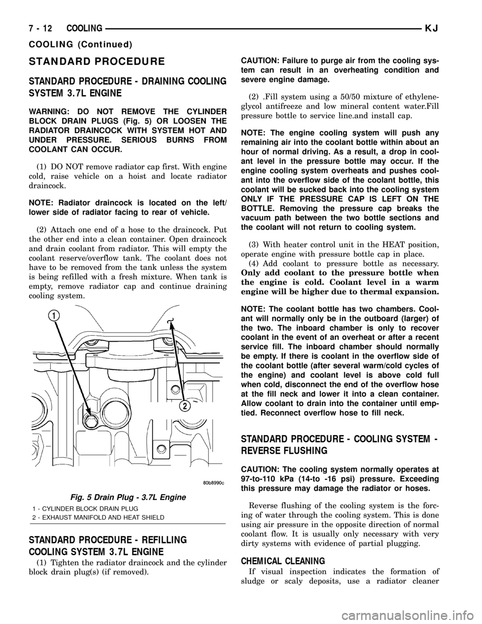
WARNING: DO NOT REMOVE THE CYLINDER
BLOCK DRAIN PLUGS (Fig. 5) OR LOOSEN THE
RADIATOR DRAINCOCK WITH SYSTEM HOT AND
UNDER PRESSURE. SERIOUS BURNS FROM
COOLANT CAN OCCUR.
(1) DO NOT remove radiator cap first. With engine
cold, raise vehicle on a hoist and locate radiator
draincock.
NOTE: Radiator draincock is located on the left/
lower side of radiator facing to rear of vehicle.
(2) Attach one end of a hose to the draincock. Put
the other end into a clean container. Open draincock
and drain coolant from radiator. This will empty the
coolant reserve/overflow tank. The coolant does not
have to be removed from the tank unless the system
is being refilled with a fresh mixture. When tank is
empty, remove radiator cap and continue draining
cooling system.
STANDARD PROCEDURE - REFILLING
COOLING SYSTEM 3.7L ENGINE
(1) Tighten the radiator draincock and the cylinder
block drain plug(s) (if removed).CAUTION: Failure to purge air from the cooling sys-
tem can result in an overheating condition and
severe engine damage.
(2) .Fill system using a 50/50 mixture of ethylene-
glycol antifreeze and low mineral content water.Fill
pressure bottle to service line.and install cap.
NOTE: The engine cooling system will push any
remaining air into the coolant bottle within about an
hour of normal driving. As a result, a drop in cool-
ant level in the pressure bottle may occur. If the
engine cooling system overheats and pushes cool-
ant into the overflow side of the coolant bottle, this
coolant will be sucked back into the cooling system
ONLY IF THE PRESSURE CAP IS LEFT ON THE
BOTTLE. Removing the pressure cap breaks the
vacuum path between the two bottle sections and
the coolant will not return to cooling system.
(3) With heater control unit in the HEAT position,
operate engine with pressure bottle cap in place.
(4) Add coolant to pressure bottle as necessary.
Only add coolant to the pressure bottle when
the engine is cold. Coolant level in a warm
engine will be higher due to thermal expansion.
NOTE: The coolant bottle has two chambers. Cool-
ant will normally only be in the outboard (larger) of
the two. The inboard chamber is only to recover
coolant in the event of an overheat or after a recent
service fill. The inboard chamber should normally
be empty. If there is coolant in the overflow side of
the coolant bottle (after several warm/cold cycles of
the engine) and coolant level is above cold full
when cold, disconnect the end of the overflow hose
at the fill neck and lower it into a clean container.
Allow coolant to drain into the container until emp-
tied. Reconnect overflow hose to fill neck.
STANDARD PROCEDURE - COOLING SYSTEM -
REVERSE FLUSHING
CAUTION: The cooling system normally operates at
97-to-110 kPa (14-to -16 psi) pressure. Exceeding
this pressure may damage the radiator or hoses.
Reverse flushing of the cooling system is the forc-
ing of water through the cooling system. This is done
using air pressure in the opposite direction of normal
coolant flow. It is usually only necessary with very
dirty systems with evidence of partial plugging.
CHEMICAL CLEANING
If visual inspection indicates the formation of
sludge or scaly deposits, use a radiator cleaner
Fig. 5 Drain Plug - 3.7L Engine
1 - CYLINDER BLOCK DRAIN PLUG
2 - EXHAUST MANIFOLD AND HEAT SHIELD
7 - 12 COOLINGKJ
COOLING (Continued)