Psi JEEP LIBERTY 2002 KJ / 1.G User Guide
[x] Cancel search | Manufacturer: JEEP, Model Year: 2002, Model line: LIBERTY, Model: JEEP LIBERTY 2002 KJ / 1.GPages: 1803, PDF Size: 62.3 MB
Page 98 of 1803
REAR AXLE - 198RBI
TABLE OF CONTENTS
page page
REAR AXLE - 198RBI
DESCRIPTION.........................49
OPERATION...........................49
DIAGNOSIS AND TESTING - AXLE..........51
REMOVAL.............................54
INSTALLATION.........................54
ADJUSTMENTS
ADJUSTMENT........................55
SPECIFICATIONS - REAR AXLE............62
SPECIAL TOOLS
REAR AXLE..........................63
AXLE SHAFTS
REMOVAL.............................65
INSTALLATION.........................65
AXLE BEARING/SEAL
REMOVAL.............................66
INSTALLATION.........................67
PINION SEAL
REMOVAL.............................68INSTALLATION.........................68
COLLAPSIBLE SPACER
REMOVAL.............................70
INSTALLATION.........................70
DIFFERENTIAL
REMOVAL.............................71
INSTALLATION.........................73
DIFFERENTIAL - TRAC-LOK
DIAGNOSIS AND TESTING - TRAC-LOKT.....74
DISASSEMBLY.........................75
CLEANING............................77
INSPECTION..........................77
ASSEMBLY............................77
DIFFERENTIAL CASE BEARINGS
REMOVAL.............................79
INSTALLATION.........................79
PINION GEAR/RING GEAR/TONE RING
REMOVAL.............................79
INSTALLATION.........................82
REAR AXLE - 198RBI
DESCRIPTION
The Rear Beam-design Iron (RBI) axle housing has
an iron center casting (differential housing) with axle
shaft tubes extending from either side. The tubes are
pressed into and welded to the differential housing to
form a one-piece axle housing. The axles are
equipped with semi±floating axle shafts, meaning
that loads are supported by the axle shaft and bear-
ings. The axle shafts are retained by the unit bear-
ing, retainer plate and bolts.
The integral type, hypoid gear design, housing has
the centerline of the pinion set below the centerline
of the ring gear. The differential case is a one-piece
design. The differential pinion mate shaft is retained
with a threaded screw. Differential bearing preload
and ring gear backlash is adjusted by the use of
selective spacer shims. Pinion bearing preload is set
and maintained by the use of a collapsible spacer
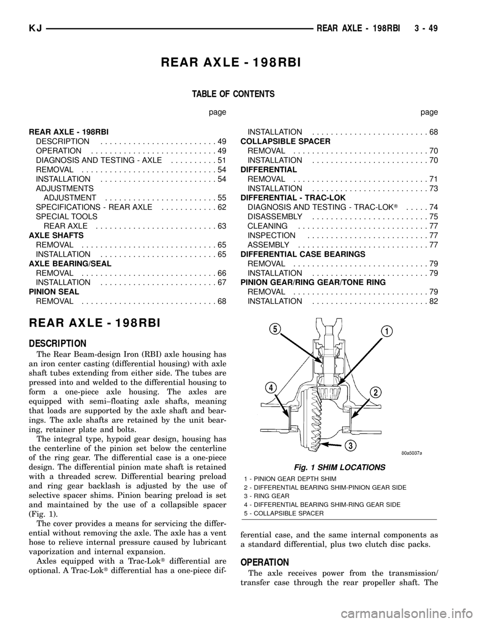
(Fig. 1).
The cover provides a means for servicing the differ-
ential without removing the axle. The axle has a vent
hose to relieve internal pressure caused by lubricant
vaporization and internal expansion.
Axles equipped with a Trac-Loktdifferential are
optional. A Trac-Loktdifferential has a one-piece dif-ferential case, and the same internal components as
a standard differential, plus two clutch disc packs.
OPERATION
The axle receives power from the transmission/
transfer case through the rear propeller shaft. The
Fig. 1 SHIM LOCATIONS
1 - PINION GEAR DEPTH SHIM
2 - DIFFERENTIAL BEARING SHIM-PINION GEAR SIDE
3 - RING GEAR
4 - DIFFERENTIAL BEARING SHIM-RING GEAR SIDE
5 - COLLAPSIBLE SPACER
KJREAR AXLE - 198RBI 3 - 49
Page 104 of 1803
(10) Install axle vent hose.
(11) Install propeller shaft with reference marks.
(12) Install the wheels and tires.
(13) Add gear lubricant to specifications, if neces-
sary.
(14) Remove lifting device from axle and lower the
vehicle.
(15) Tighten the lower control arm bolts to torque
specification.
ADJUSTMENTS
ADJUSTMENT
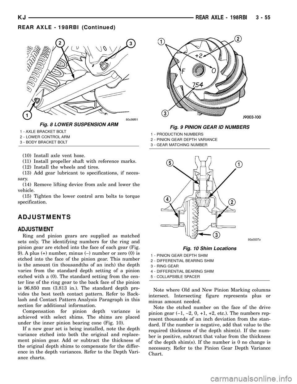
Ring and pinion gears are supplied as matched
sets only. The identifying numbers for the ring and
pinion gear are etched into the face of each gear (Fig.
9). A plus (+) number, minus (±) number or zero (0) is
etched into the face of the pinion gear. This number
is the amount (in thousandths of an inch) the depth
varies from the standard depth setting of a pinion
etched with a (0). The standard setting from the cen-
ter line of the ring gear to the back face of the pinion
is 96.850 mm (3.813 in.). The standard depth pro-
vides the best teeth contact pattern. Refer to Back-
lash and Contact Pattern Analysis Paragraph in this
section for additional information.
Compensation for pinion depth variance is
achieved with select shims. The shims are placed
under the inner pinion bearing cone (Fig. 10).
If a new gear set is being installed, note the depth
variance etched into both the original and replace-
ment pinion gear. Add or subtract the thickness of
the original depth shims to compensate for the differ-
ence in the depth variances. Refer to the Depth Vari-
ance charts.Note where Old and New Pinion Marking columns
intersect. Intersecting figure represents plus or
minus amount needed.
Note the etched number on the face of the drive
pinion gear (±1, ±2, 0, +1, +2, etc.). The numbers rep-
resent thousands of an inch deviation from the stan-
dard. If the number is negative, add that value to the
required thickness of the depth shim(s). If the num-
ber is positive, subtract that value from the thickness
of the depth shim(s). If the number is 0 no change is
necessary. Refer to the Pinion Gear Depth Variance
Chart.
Fig. 8 LOWER SUSPENSION ARM
1 - AXLE BRACKET BOLT
2 - LOWER CONTROL ARM
3 - BODY BRACKET BOLTFig. 9 PINION GEAR ID NUMBERS
1 - PRODUCTION NUMBERS
2 - PINION GEAR DEPTH VARIANCE
3 - GEAR MATCHING NUMBER
Fig. 10 Shim Locations
1 - PINION GEAR DEPTH SHIM
2 - DIFFERENTIAL BEARING SHIM
3 - RING GEAR
4 - DIFFERENTIAL BEARING SHIM
5 - COLLAPSIBLE SPACER
KJREAR AXLE - 198RBI 3 - 55
REAR AXLE - 198RBI (Continued)
Page 106 of 1803
(5) Assemble Dial Indicator C-3339 into Scooter
Block D-115-2 and secure set screw.
(6) Position Scooter Block/Dial Indicator flush on
the pinion height block. Hold scooter block and zero
the dial indicator.
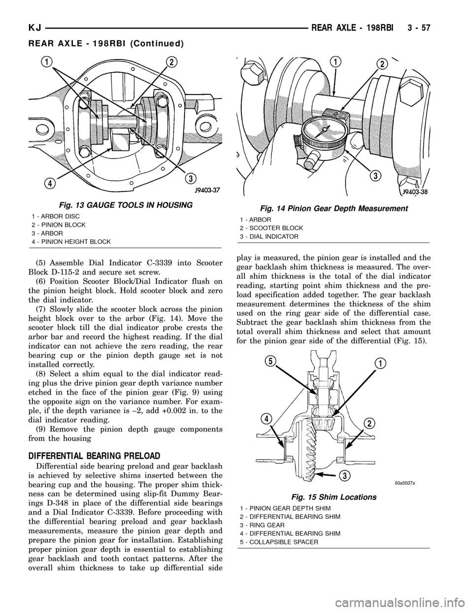
(7) Slowly slide the scooter block across the pinion
height block over to the arbor (Fig. 14). Move the
scooter block till the dial indicator probe crests the
arbor bar and record the highest reading. If the dial
indicator can not achieve the zero reading, the rear
bearing cup or the pinion depth gauge set is not
installed correctly.
(8) Select a shim equal to the dial indicator read-
ing plus the drive pinion gear depth variance number
etched in the face of the pinion gear (Fig. 9) using
the opposite sign on the variance number. For exam-
ple, if the depth variance is ±2, add +0.002 in. to the
dial indicator reading.
(9) Remove the pinion depth gauge components
from the housing
DIFFERENTIAL BEARING PRELOAD
Differential side bearing preload and gear backlash
is achieved by selective shims inserted between the
bearing cup and the housing. The proper shim thick-
ness can be determined using slip-fit Dummy Bear-
ings D-348 in place of the differential side bearings
and a Dial Indicator C-3339. Before proceeding with
the differential bearing preload and gear backlash
measurements, measure the pinion gear depth and
prepare the pinion gear for installation. Establishing
proper pinion gear depth is essential to establishing
gear backlash and tooth contact patterns. After the
overall shim thickness to take up differential sideplay is measured, the pinion gear is installed and the
gear backlash shim thickness is measured. The over-
all shim thickness is the total of the dial indicator
reading, starting point shim thickness and the pre-
load specification added together. The gear backlash
measurement determines the thickness of the shim
used on the ring gear side of the differential case.
Subtract the gear backlash shim thickness from the
total overall shim thickness and select that amount
for the pinion gear side of the differential (Fig. 15).
Fig. 13 GAUGE TOOLS IN HOUSING
1 - ARBOR DISC
2 - PINION BLOCK
3 - ARBOR
4 - PINION HEIGHT BLOCKFig. 14 Pinion Gear Depth Measurement
1 - ARBOR
2 - SCOOTER BLOCK
3 - DIAL INDICATOR
Fig. 15 Shim Locations
1 - PINION GEAR DEPTH SHIM
2 - DIFFERENTIAL BEARING SHIM
3 - RING GEAR
4 - DIFFERENTIAL BEARING SHIM
5 - COLLAPSIBLE SPACER
KJREAR AXLE - 198RBI 3 - 57
REAR AXLE - 198RBI (Continued)
Page 117 of 1803
PINION SEAL
REMOVAL
(1) Raise and support the vehicle.
(2) Remove wheel and tire assemblies.
(3) Remove rear brake rotors drums.
(4) Mark propeller shaft and pinion yoke for
installation reference.
(5) Remove the propeller shaft from the yoke.
(6) Rotate pinion gear three or four times and ver-
ify that pinion rotates smoothly.
(7) Measure and record torque to rotate the pinion
gear with an inch pound dial-type torque wrench.
(8) With a short piece of pipe and Spanner Wrench
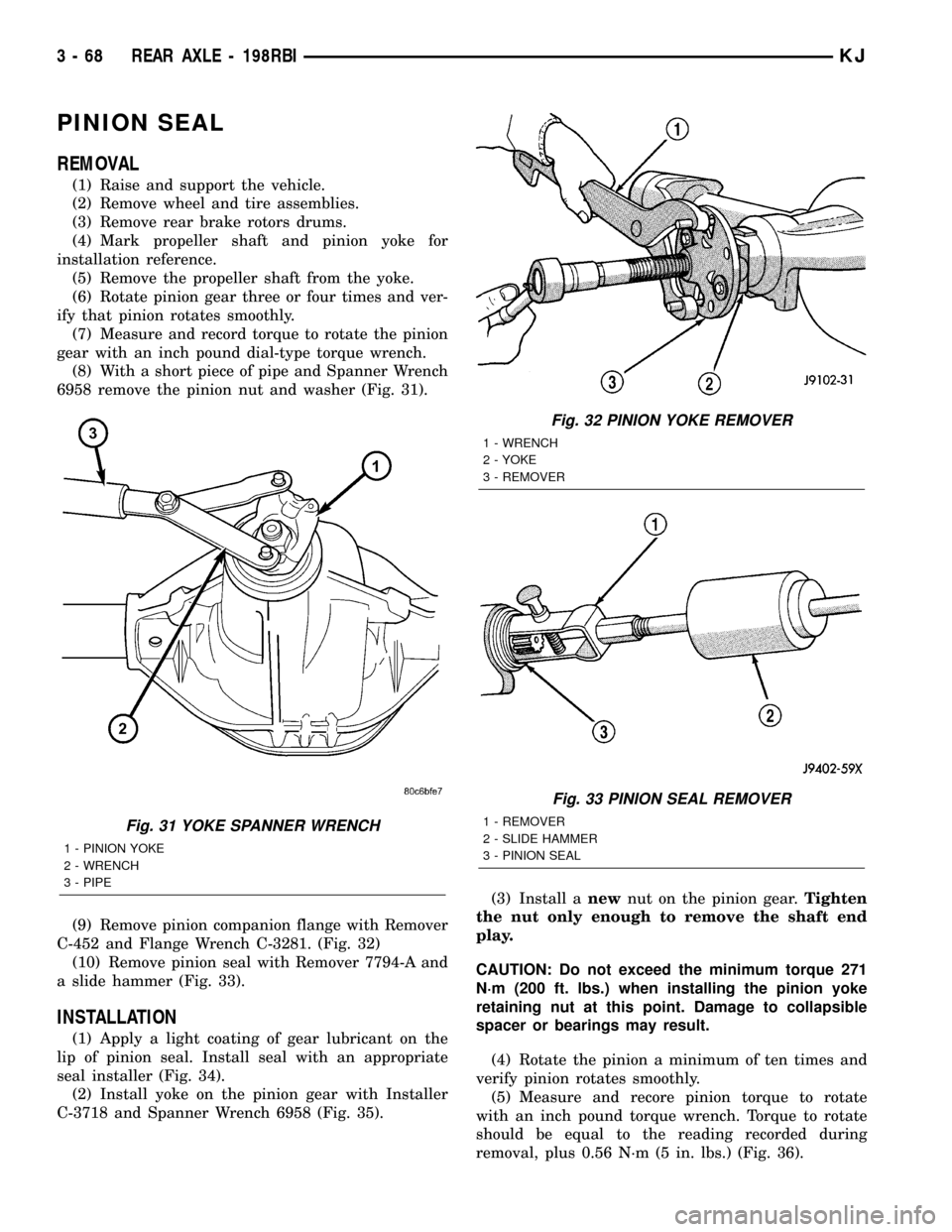
6958 remove the pinion nut and washer (Fig. 31).
(9) Remove pinion companion flange with Remover
C-452 and Flange Wrench C-3281. (Fig. 32)
(10) Remove pinion seal with Remover 7794-A and
a slide hammer (Fig. 33).
INSTALLATION
(1) Apply a light coating of gear lubricant on the
lip of pinion seal. Install seal with an appropriate
seal installer (Fig. 34).
(2) Install yoke on the pinion gear with Installer
C-3718 and Spanner Wrench 6958 (Fig. 35).(3) Install anewnut on the pinion gear.Tighten
the nut only enough to remove the shaft end
play.
CAUTION: Do not exceed the minimum torque 271
N´m (200 ft. lbs.) when installing the pinion yoke
retaining nut at this point. Damage to collapsible
spacer or bearings may result.
(4) Rotate the pinion a minimum of ten times and
verify pinion rotates smoothly.
(5) Measure and recore pinion torque to rotate
with an inch pound torque wrench. Torque to rotate
should be equal to the reading recorded during
removal, plus 0.56 N´m (5 in. lbs.) (Fig. 36).
Fig. 31 YOKE SPANNER WRENCH
1 - PINION YOKE
2 - WRENCH
3 - PIPE
Fig. 32 PINION YOKE REMOVER
1 - WRENCH
2 - YOKE
3 - REMOVER
Fig. 33 PINION SEAL REMOVER
1 - REMOVER
2 - SLIDE HAMMER
3 - PINION SEAL
3 - 68 REAR AXLE - 198RBIKJ
Page 118 of 1803
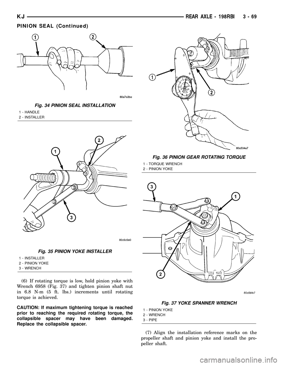
(6) If rotating torque is low, hold pinion yoke with
Wrench 6958 (Fig. 37) and tighten pinion shaft nut
in 6.8 N´m (5 ft. lbs.) increments until rotating
torque is achieved.
CAUTION: If maximum tightening torque is reached
prior to reaching the required rotating torque, the
collapsible spacer may have been damaged.
Replace the collapsible spacer.
(7) Align the installation reference marks on the
propeller shaft and pinion yoke and install the pro-
peller shaft.
Fig. 34 PINION SEAL INSTALLATION
1 - HANDLE
2 - INSTALLER
Fig. 35 PINION YOKE INSTALLER
1 - INSTALLER
2 - PINION YOKE
3 - WRENCH
Fig. 36 PINION GEAR ROTATING TORQUE
1 - TORQUE WRENCH
2 - PINION YOKE
Fig. 37 YOKE SPANNER WRENCH
1 - PINION YOKE
2 - WRENCH
3 - PIPE
KJREAR AXLE - 198RBI 3 - 69
PINION SEAL (Continued)
Page 119 of 1803
(8) Fill differential with gear lubricant.
(9) Install the brake drums
(10) Install wheel and tire assemblies.
(11) Lower the vehicle.
COLLAPSIBLE SPACER
REMOVAL
(1) Raise and support the vehicle.
(2) Remove wheel and tire assemblies.
(3) Remove rear brake drums.
(4) Mark the propeller shaft and pinion yoke for
installation reference.
(5) Remove the propeller shaft from the yoke.
(6) Rotate the pinion gear three or four times.
(7) Measure and record torque to rotate the pinion
gear with an inch pound dial-type torque wrench.
(8) Hold pinion yoke with Spanner Wrench 6958
and remove pinion nut and washer.
(9) Remove the pinion yoke with Remover C-452
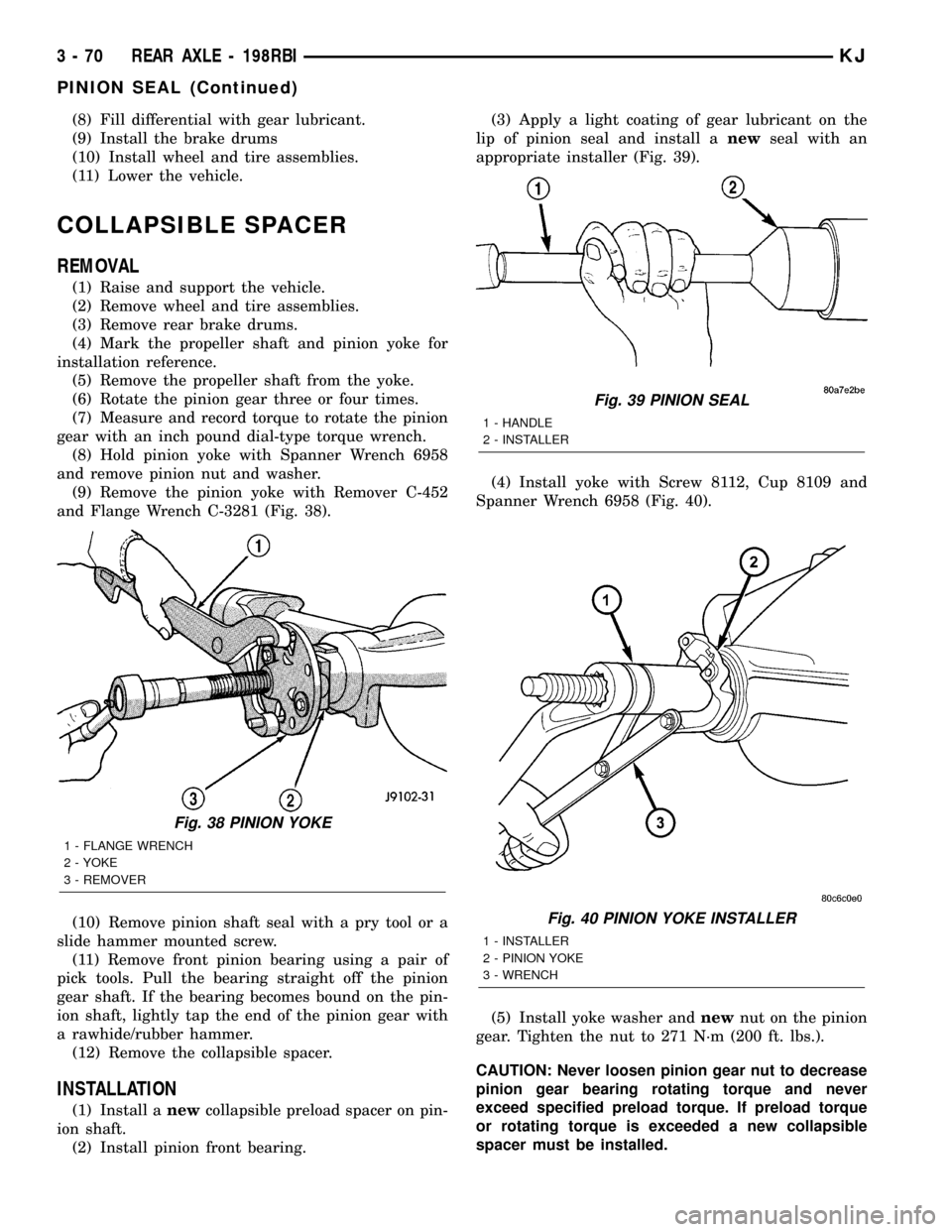
and Flange Wrench C-3281 (Fig. 38).
(10) Remove pinion shaft seal with a pry tool or a
slide hammer mounted screw.
(11) Remove front pinion bearing using a pair of
pick tools. Pull the bearing straight off the pinion
gear shaft. If the bearing becomes bound on the pin-
ion shaft, lightly tap the end of the pinion gear with
a rawhide/rubber hammer.
(12) Remove the collapsible spacer.
INSTALLATION
(1) Install anewcollapsible preload spacer on pin-
ion shaft.
(2) Install pinion front bearing.(3) Apply a light coating of gear lubricant on the
lip of pinion seal and install anewseal with an
appropriate installer (Fig. 39).
(4) Install yoke with Screw 8112, Cup 8109 and
Spanner Wrench 6958 (Fig. 40).
(5) Install yoke washer andnewnut on the pinion
gear. Tighten the nut to 271 N´m (200 ft. lbs.).
CAUTION: Never loosen pinion gear nut to decrease
pinion gear bearing rotating torque and never
exceed specified preload torque. If preload torque
or rotating torque is exceeded a new collapsible
spacer must be installed.
Fig. 38 PINION YOKE
1 - FLANGE WRENCH
2 - YOKE
3 - REMOVER
Fig. 39 PINION SEAL
1 - HANDLE
2 - INSTALLER
Fig. 40 PINION YOKE INSTALLER
1 - INSTALLER
2 - PINION YOKE
3 - WRENCH
3 - 70 REAR AXLE - 198RBIKJ
PINION SEAL (Continued)
Page 120 of 1803
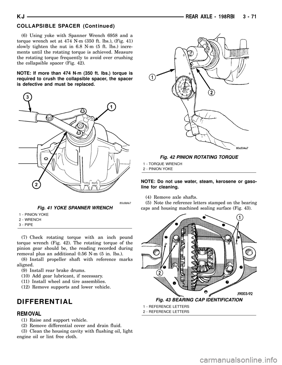
(6) Using yoke with Spanner Wrench 6958 and a
torque wrench set at 474 N´m (350 ft. lbs.), (Fig. 41)
slowly tighten the nut in 6.8 N´m (5 ft. lbs.) incre-
ments until the rotating torque is achieved. Measure
the rotating torque frequently to avoid over crushing
the collapsible spacer (Fig. 42).
NOTE: If more than 474 N´m (350 ft. lbs.) torque is
required to crush the collapsible spacer, the spacer
is defective and must be replaced.
(7) Check rotating torque with an inch pound
torque wrench (Fig. 42). The rotating torque of the
pinion gear should be, the reading recorded during
removal plus an additional 0.56 N´m (5 in. lbs.).
(8) Install propeller shaft with reference marks
aligned.
(9) Install rear brake drums.
(10) Add gear lubricant, if necessary.
(11) Install wheel and tire assemblies.
(12) Remove supports and lower vehicle.
DIFFERENTIAL
REMOVAL
(1) Raise and support vehicle.
(2) Remove differential cover and drain fluid.
(3) Clean the housing cavity with flushing oil, light
engine oil or lint free cloth.NOTE: Do not use water, steam, kerosene or gaso-
line for cleaning.
(4) Remove axle shafts.
(5)
Note the reference letters stamped on the bearing
caps and housing machined sealing surface (Fig. 43).
Fig. 41 YOKE SPANNER WRENCH
1 - PINION YOKE
2 - WRENCH
3 - PIPE
Fig. 42 PINION ROTATING TORQUE
1 - TORQUE WRENCH
2 - PINION YOKE
Fig. 43 BEARING CAP IDENTIFICATION
1 - REFERENCE LETTERS
2 - REFERENCE LETTERS
KJREAR AXLE - 198RBI 3 - 71
COLLAPSIBLE SPACER (Continued)
Page 130 of 1803
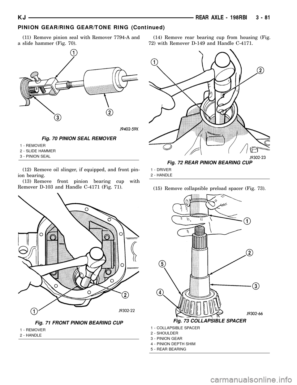
(11) Remove pinion seal with Remover 7794-A and
a slide hammer (Fig. 70).
(12) Remove oil slinger, if equipped, and front pin-
ion bearing.
(13) Remove front pinion bearing cup with
Remover D-103 and Handle C-4171 (Fig. 71).(14) Remove rear bearing cup from housing (Fig.
72) with Remover D-149 and Handle C-4171.
(15) Remove collapsible preload spacer (Fig. 73).
Fig. 70 PINION SEAL REMOVER
1 - REMOVER
2 - SLIDE HAMMER
3 - PINION SEAL
Fig. 71 FRONT PINION BEARING CUP
1 - REMOVER
2 - HANDLE
Fig. 72 REAR PINION BEARING CUP
1 - DRIVER
2 - HANDLE
Fig. 73 COLLAPSIBLE SPACER
1 - COLLAPSIBLE SPACER
2 - SHOULDER
3 - PINION GEAR
4 - PINION DEPTH SHIM
5 - REAR BEARING
KJREAR AXLE - 198RBI 3 - 81
PINION GEAR/RING GEAR/TONE RING (Continued)
Page 132 of 1803
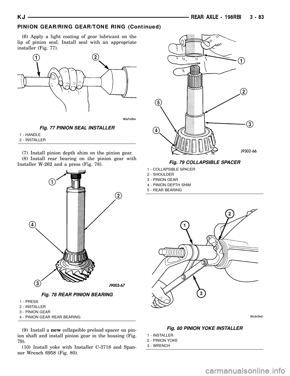
(6) Apply a light coating of gear lubricant on the
lip of pinion seal. Install seal with an appropriate
installer (Fig. 77).
(7) Install pinion depth shim on the pinion gear.
(8) Install rear bearing on the pinion gear with
Installer W-262 and a press (Fig. 78).
(9) Install anewcollapsible preload spacer on pin-
ion shaft and install pinion gear in the housing (Fig.
79).
(10) Install yoke with Installer C-3718 and Span-
ner Wrench 6958 (Fig. 80).
Fig. 77 PINION SEAL INSTALLER
1 - HANDLE
2 - INSTALLER
Fig. 78 REAR PINION BEARING
1 - PRESS
2 - INSTALLER
3 - PINION GEAR
4 - PINION GEAR REAR BEARING
Fig. 79 COLLAPSIBLE SPACER
1 - COLLAPSIBLE SPACER
2 - SHOULDER
3 - PINION GEAR
4 - PINION DEPTH SHIM
5 - REAR BEARING
Fig. 80 PINION YOKE INSTALLER
1 - INSTALLER
2 - PINION YOKE
3 - WRENCH
KJREAR AXLE - 198RBI 3 - 83
PINION GEAR/RING GEAR/TONE RING (Continued)
Page 133 of 1803
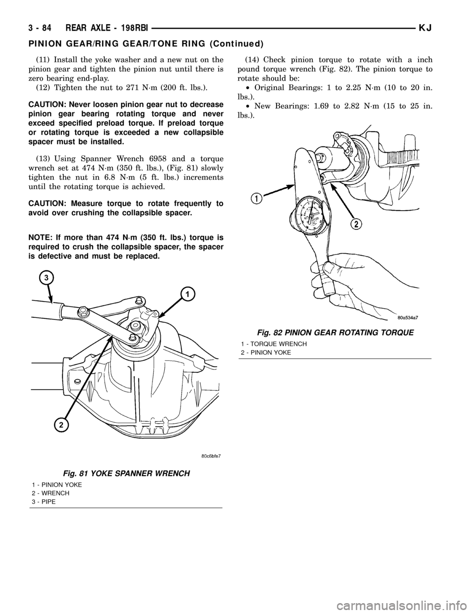
(11) Install the yoke washer and a new nut on the
pinion gear and tighten the pinion nut until there is
zero bearing end-play.
(12) Tighten the nut to 271 N´m (200 ft. lbs.).
CAUTION: Never loosen pinion gear nut to decrease
pinion gear bearing rotating torque and never
exceed specified preload torque. If preload torque
or rotating torque is exceeded a new collapsible
spacer must be installed.
(13) Using Spanner Wrench 6958 and a torque
wrench set at 474 N´m (350 ft. lbs.), (Fig. 81) slowly
tighten the nut in 6.8 N´m (5 ft. lbs.) increments
until the rotating torque is achieved.
CAUTION: Measure torque to rotate frequently to
avoid over crushing the collapsible spacer.
NOTE: If more than 474 N´m (350 ft. lbs.) torque is
required to crush the collapsible spacer, the spacer
is defective and must be replaced.(14) Check pinion torque to rotate with a inch
pound torque wrench (Fig. 82). The pinion torque to
rotate should be:
²Original Bearings: 1 to 2.25 N´m (10 to 20 in.
lbs.).
²New Bearings: 1.69 to 2.82 N´m (15 to 25 in.
lbs.).
Fig. 81 YOKE SPANNER WRENCH
1 - PINION YOKE
2 - WRENCH
3 - PIPE
Fig. 82 PINION GEAR ROTATING TORQUE
1 - TORQUE WRENCH
2 - PINION YOKE
3 - 84 REAR AXLE - 198RBIKJ
PINION GEAR/RING GEAR/TONE RING (Continued)