tow JEEP PATRIOT 2013 1.G User Guide
[x] Cancel search | Manufacturer: JEEP, Model Year: 2013, Model line: PATRIOT, Model: JEEP PATRIOT 2013 1.GPages: 108, PDF Size: 3.17 MB
Page 3 of 108
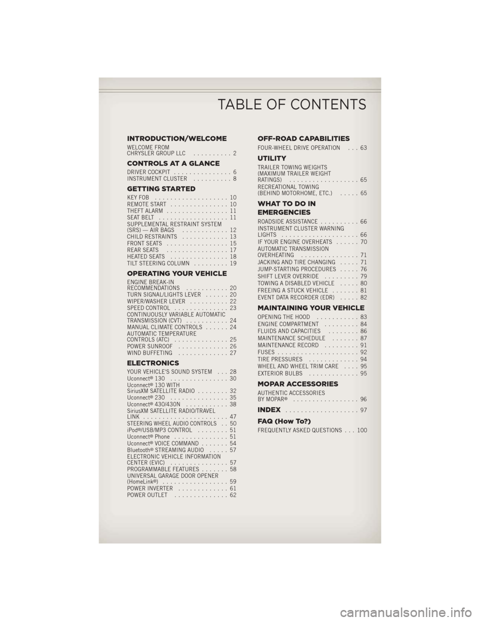
INTRODUCTION/WELCOME
WELCOME FROM
CHRYSLER GROUP LLC.......... 2
CONTROLS AT A GLANCE
DRIVER COCKPIT............... 6
INSTRUMENT CLUSTER .......... 8
GETTING STARTED
KEYFOB ................... 10
REMOTE START............... 10
THEFT ALARM ................ 11
SEATBELT .................. 11
SUPPLEMENTAL RESTRAINT SYSTEM
(SRS) — AIR BAGS ............ 12
CHILD RESTRAINTS ............ 13
FRONT SEATS ................ 15
REAR SEATS ................ 17
HEATEDSEATS ............... 18
TILT STEERING COLUMN ......... 19
OPERATING YOUR VEHICLE
ENGINE BREAK-IN
RECOMMENDATIONS........... 20
TURN SIGNAL/LIGHTS LEVER ...... 20
WIPER/WASHER LEVER .......... 22
SPEED CONTROL .............. 23
CONTINUOUSLY VARIABLE AUTOMATIC
TRANSMISSION (CVT) ........... 24
MANUAL CLIMATE CONTROLS ...... 24
AUTOMATIC TEMPERATURE
CONTROLS (ATC) .............. 25
POWER SUNROOF ............. 26
WIND BUFFETING ............. 27
ELECTRONICS
YOUR VEHICLE'S SOUND SYSTEM . . . 28
Uconnect®130 ............... 30
Uconnect®130 WITH
SiriusXM SATELLITE RADIO ........ 32
Uconnect
®230 ............... 35
Uconnect®430/430N ........... 38
SiriusXM SATELLITE RADIO/TRAVEL
LINK ...................... 47
STEERING WHEEL AUDIO CONTROLS.. 50
iPod®/USB/MP3 CONTROL ........ 51
Uconnect®Phone .............. 51
Uconnect®VOICE COMMAND ....... 54
Bluetooth®STREAMING AUDIO ..... 57
ELECTRONIC VEHICLE INFORMATION
CENTER (EVIC) ............... 57
PROGRAMMABLE FEATURES ....... 58
UNIVERSAL GARAGE DOOR OPENER
(HomeLink
®) ................. 59
POWER INVERTER ............. 61
POWER OUTLET .............. 62
OFF-ROAD CAPABILITIES
FOUR-WHEEL DRIVE OPERATION . . . 63
UTILITY
TRAILER TOWING WEIGHTS
(MAXIMUM TRAILER WEIGHT
RATINGS).................. 65
RECREATIONAL TOWING
(BEHIND MOTORHOME, ETC.) ..... 65
WHATTODOIN
EMERGENCIES
ROADSIDE ASSISTANCE.......... 66
INSTRUMENT CLUSTER WARNING
LIGHTS .................... 66
IF YOUR ENGINE OVERHEATS ...... 70
AUTOMATIC TRANSMISSION
OVERHEATING ............... 71
JACKING AND TIRE CHANGING ..... 71
JUMP-STARTING PROCEDURES ..... 76
SHIFT LEVER OVERRIDE ......... 79
TOWING A DISABLED VEHICLE ..... 80
FREEING A STUCK VEHICLE ....... 81
EVENT DATA RECORDER (EDR) ..... 82
MAINTAINING YOUR VEHICLE
OPENING THE HOOD........... 83
ENGINE COMPARTMENT ......... 84
FLUIDS AND CAPACITIES ........ 86
MAINTENANCE SCHEDULE ....... 87
MAINTENANCE RECORD ......... 91
FUSES ..................... 92
TIRE PRESSURES ............. 94
WHEEL AND WHEEL TRIM CARE .... 95
EXTERIOR BULBS ............. 95
MOPAR ACCESSORIES
AUTHENTIC ACCESSORIES
BY MOPAR®................. 96
INDEX................... 97
FAQ(HowTo?)
FREQUENTLY ASKED QUESTIONS . . . 100
TABLE OF CONTENTS
Page 23 of 108
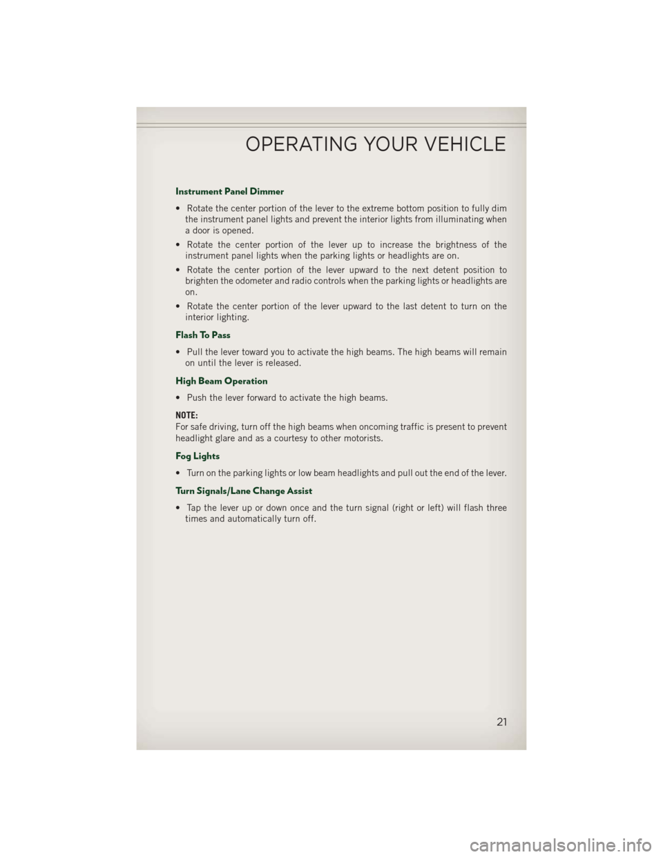
Instrument Panel Dimmer
• Rotate the center portion of the lever to the extreme bottom position to fully dimthe instrument panel lights and prevent the interior lights from illuminating when
a door is opened.
• Rotate the center portion of the lever up to increase the brightness of the instrument panel lights when the parking lights or headlights are on.
• Rotate the center portion of the lever upward to the next detent position to brighten the odometer and radio controls when the parking lights or headlights are
on.
• Rotate the center portion of the lever upward to the last detent to turn on the interior lighting.
Flash To Pass
• Pull the lever toward you to activate the high beams. The high beams will remainon until the lever is released.
High Beam Operation
• Push the lever forward to activate the high beams.
NOTE:
For safe driving, turn off the high beams when oncoming traffic is present to prevent
headlight glare and as a courtesy to other motorists.
Fog Lights
• Turn on the parking lights or low beam headlights and pull out the end of the lever.
Turn Signals/Lane Change Assist
• Tap the lever up or down once and the turn signal (right or left) will flash threetimes and automatically turn off.
OPERATING YOUR VEHICLE
21
Page 24 of 108
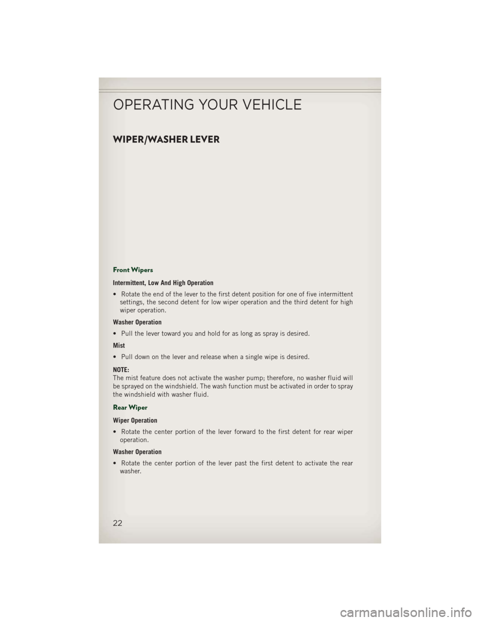
WIPER/WASHER LEVER
Front Wipers
Intermittent, Low And High Operation
• Rotate the end of the lever to the first detent position for one of five intermittentsettings, the second detent for low wiper operation and the third detent for high
wiper operation.
Washer Operation
• Pull the lever toward you and hold for as long as spray is desired.
Mist
• Pull down on the lever and release when a single wipe is desired.
NOTE:
The mist feature does not activate the washer pump; therefore, no washer fluid will
be sprayed on the windshield. The wash function must be activated in order to spray
the windshield with washer fluid.
Rear Wiper
Wiper Operation
• Rotate the center portion of the lever forward to the first detent for rear wiper operation.
Washer Operation
• Rotate the center portion of the lever past the first detent to activate the rear washer.
OPERATING YOUR VEHICLE
22
Page 67 of 108
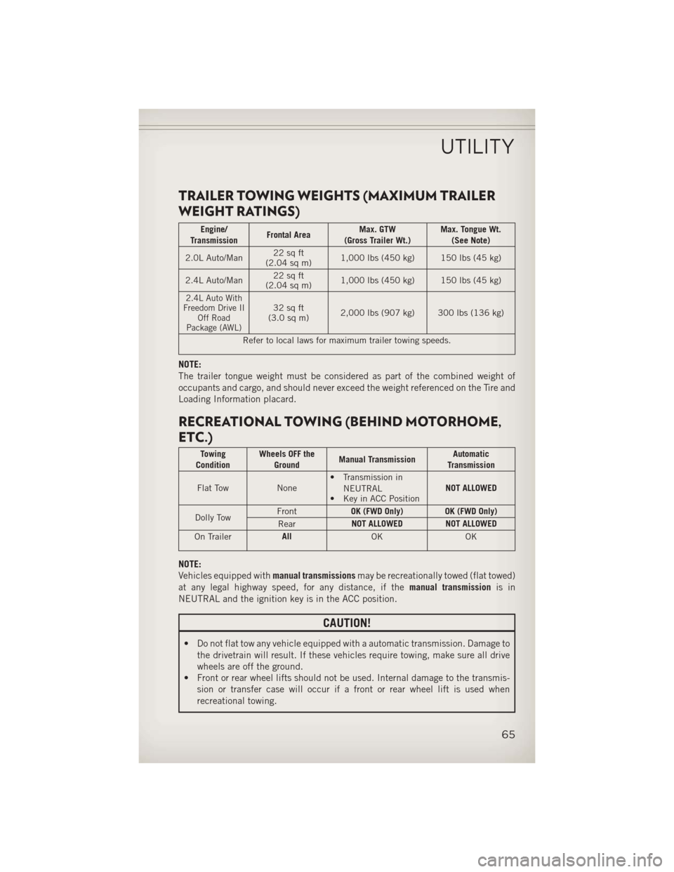
TRAILER TOWING WEIGHTS (MAXIMUM TRAILER
WEIGHT RATINGS)
Engine/
Transmission Frontal Area Max. GTW
(Gross Trailer Wt.) Max. Tongue Wt.
(See Note)
2.0L Auto/Man 22 sq ft
(2.04 sq m) 1,000 lbs (450 kg) 150 lbs (45 kg)
2.4L Auto/Man 22 sq ft
(2.04 sq m) 1,000 lbs (450 kg) 150 lbs (45 kg)
2.4L Auto With
Freedom Drive II Off Road
Package (AWL)32 sq ft
(3.0 sq m) 2,000 lbs (907 kg) 300 lbs (136 kg)
Refer to local laws for maximum trailer towing speeds.
NOTE:
The trailer tongue weight must be considered as part of the combined weight of
occupants and cargo, and should never exceed the weight referenced on the Tire and
Loading Information placard.
RECREATIONAL TOWING (BEHIND MOTORHOME,
ETC.)
Towing
Condition Wheels OFF the
Ground Manual Transmission Automatic
Transmission
Flat Tow None• Transmission in
NEUTRAL
• Key in ACC Position NOT ALLOWED
Dolly Tow Front
OK (FWD Only) OK (FWD Only)
Rear NOT ALLOWED NOT ALLOWED
On Trailer All
OK OK
NOTE:
Vehicles equipped withmanual transmissionsmay be recreationally towed (flat towed)
at any legal highway speed, for any distance, if the manual transmissionis in
NEUTRAL and the ignition key is in the ACC position.
CAUTION!
• Do not flat tow any vehicle equipped with a automatic transmission. Damage to the drivetrain will result. If these vehicles require towing, make sure all drive
wheels are off the ground.
• Front or rear wheel lifts should not be used. Internal damage to the transmis-
sion or transfer case will occur if a front or rear wheel lift is used when
recreational towing.
UTILITY
65
Page 70 of 108
• We recommend that you do not operate the vehicle or engine damage will occur.Have the vehicle serviced immediately.
WARNING!
A hot engine cooling system is dangerous. You or others could be badly burned by
steam or boiling coolant. You may want to call an authorized dealer for service if
your vehicle overheats.
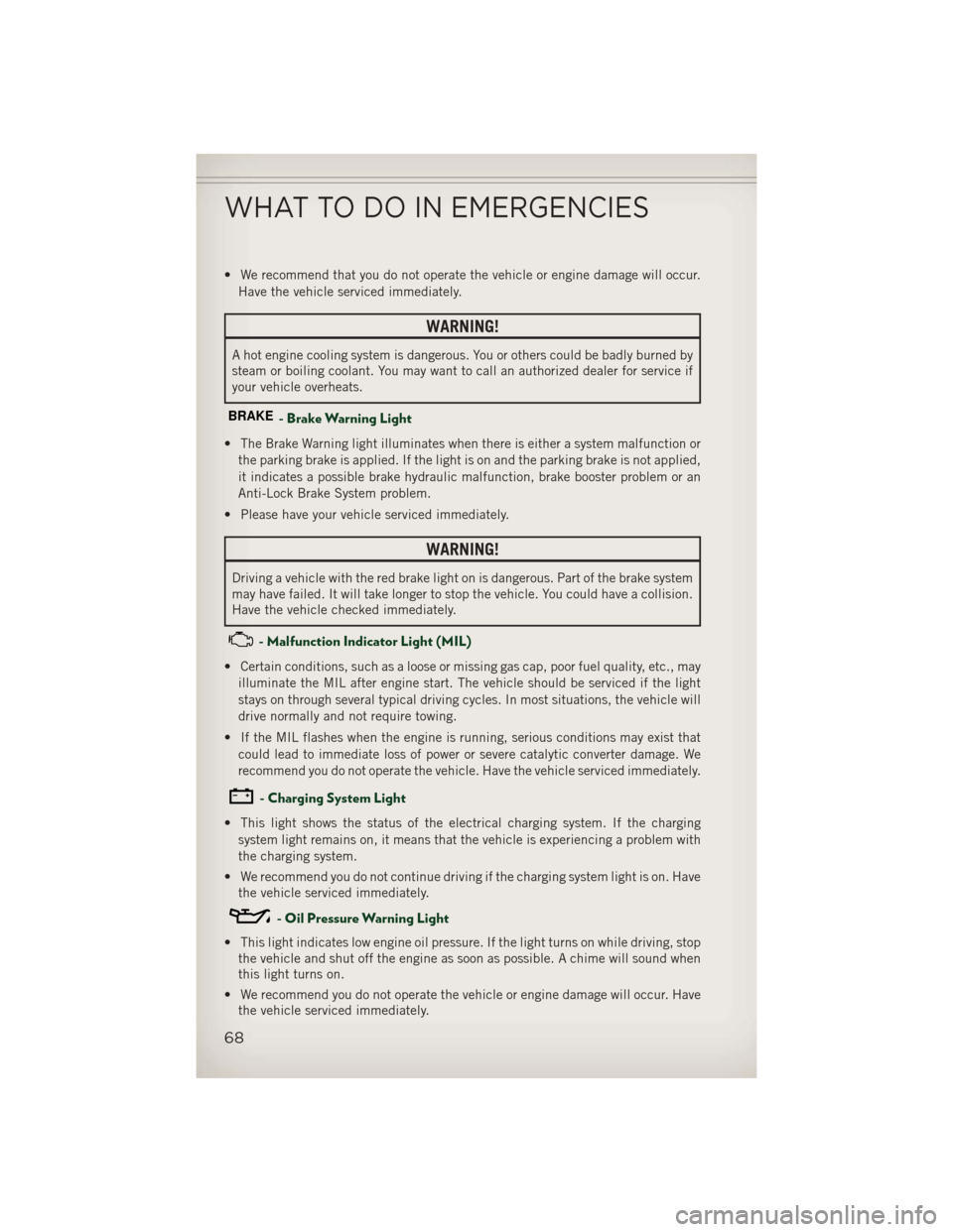
BRAKE- Brake Warning Light
• The Brake Warning light illuminates when there is either a system malfunction orthe parking brake is applied. If the light is on and the parking brake is not applied,
it indicates a possible brake hydraulic malfunction, brake booster problem or an
Anti-Lock Brake System problem.
• Please have your vehicle serviced immediately.
WARNING!
Driving a vehicle with the red brake light on is dangerous. Part of the brake system
may have failed. It will take longer to stop the vehicle. You could have a collision.
Have the vehicle checked immediately.
- Malfunction Indicator Light (MIL)
• Certain conditions, such as a loose or missing gas cap, poor fuel quality, etc., may illuminate the MIL after engine start. The vehicle should be serviced if the light
stays on through several typical driving cycles. In most situations, the vehicle will
drive normally and not require towing.
• If the MIL flashes when the engine is running, serious conditions may exist that could lead to immediate loss of power or severe catalytic converter damage. We
recommend you do not operate the vehicle. Have the vehicle serviced immediately.
- Charging System Light
• This light shows the status of the electrical charging system. If the chargingsystem light remains on, it means that the vehicle is experiencing a problem with
the charging system.
• We recommend you do not continue driving if the charging system light is on. Have the vehicle serviced immediately.
- Oil Pressure Warning Light
• This light indicates low engine oil pressure. If the light turns on while driving, stopthe vehicle and shut off the engine as soon as possible. A chime will sound when
this light turns on.
• We recommend you do not operate the vehicle or engine damage will occur. Have the vehicle serviced immediately.
WHAT TO DO IN EMERGENCIES
68
Page 71 of 108
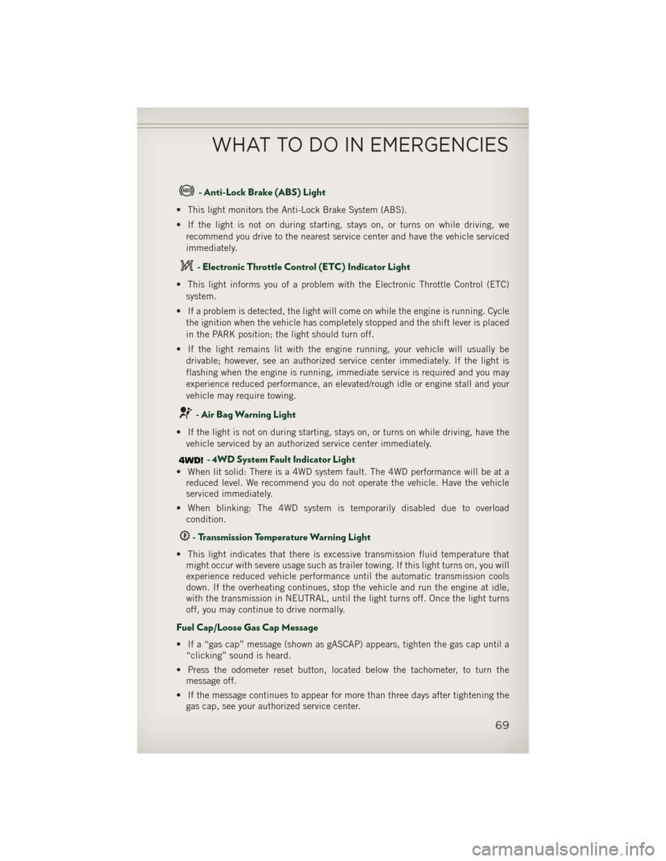
- Anti-Lock Brake (ABS) Light
• This light monitors the Anti-Lock Brake System (ABS).
• If the light is not on during starting, stays on, or turns on while driving, werecommend you drive to the nearest service center and have the vehicle serviced
immediately.
- Electronic Throttle Control (ETC) Indicator Light
• This light informs you of a problem with the Electronic Throttle Control (ETC)system.
• If a problem is detected, the light will come on while the engine is running. Cycle the ignition when the vehicle has completely stopped and the shift lever is placed
in the PARK position; the light should turn off.
• If the light remains lit with the engine running, your vehicle will usually be drivable; however, see an authorized service center immediately. If the light is
flashing when the engine is running, immediate service is required and you may
experience reduced performance, an elevated/rough idle or engine stall and your
vehicle may require towing.
- Air Bag Warning Light
• If the light is not on during starting, stays on, or turns on while driving, have thevehicle serviced by an authorized service center immediately.
- 4WD System Fault Indicator Light
• When lit solid: There is a 4WD system fault. The 4WD performance will be at areduced level. We recommend you do not operate the vehicle. Have the vehicle
serviced immediately.
• When blinking: The 4WD system is temporarily disabled due to overload condition.
- Transmission Temperature Warning Light
• This light indicates that there is excessive transmission fluid temperature thatmight occur with severe usage such as trailer towing. If this light turns on, you will
experience reduced vehicle performance until the automatic transmission cools
down. If the overheating continues, stop the vehicle and run the engine at idle,
with the transmission in NEUTRAL, until the light turns off. Once the light turns
off, you may continue to drive normally.
Fuel Cap/Loose Gas Cap Message
• If a “gas cap” message (shown as gASCAP) appears, tighten the gas cap until a“clicking” sound is heard.
• Press the odometer reset button, located below the tachometer, to turn the message off.
• If the message continues to appear for more than three days after tightening the gas cap, see your authorized service center.
WHAT TO DO IN EMERGENCIES
69
Page 73 of 108
AUTOMATIC TRANSMISSION OVERHEATING
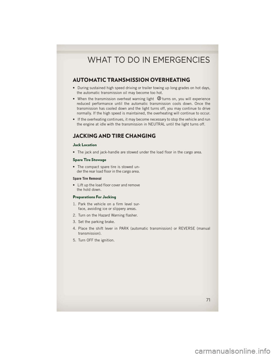
• During sustained high speed driving or trailer towing up long grades on hot days,the automatic transmission oil may become too hot.
• When the transmission overheat warning light
turns on, you will experience
reduced performance until the automatic transmission cools down. Once the
transmission has cooled down and the light turns off, you may continue to drive
normally. If the high speed is maintained, the overheating will continue to occur.
• If the overheating continues, it may become necessary to stop the vehicle and run the engine at idle with the transmission in NEUTRAL until the light turns off.
JACKING AND TIRE CHANGING
Jack Location
• The jack and jack-handle are stowed under the load floor in the cargo area.
Spare Tire Stowage
• The compact spare tire is stowed un-der the rear load floor in the cargo area.
Spare Tire Removal
• Lift up the load floor cover and removethe hold down.
Preparations For Jacking
1. Park the vehicle on a firm level sur-
face, avoiding ice or slippery areas.
2. Turn on the Hazard Warning flasher.
3. Set the parking brake.
4. Place the shift lever in PARK (automatic transmission) or REVERSE (manual transmission).
5. Turn OFF the ignition.
WHAT TO DO IN EMERGENCIES
71
Page 75 of 108
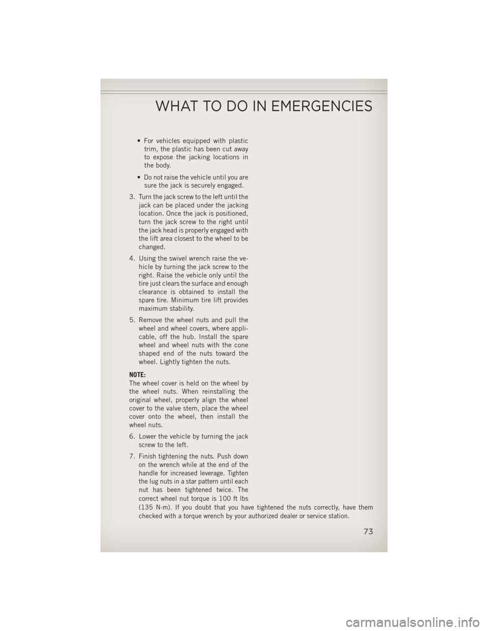
• For vehicles equipped with plastictrim, the plastic has been cut away
to expose the jacking locations in
the body.
• Do not raise the vehicle until you are sure the jack is securely engaged.
3. Turn the jack screw to the left until the jack can be placed under the jacking
location. Once the jack is positioned,
turn the jack screw to the right until
the jack head is properly engaged with
the lift area closest to the wheel to be
changed.
4. Using the swivel wrench raise the ve- hicle by turning the jack screw to the
right. Raise the vehicle only until the
tire just clears the surface and enough
clearance is obtained to install the
spare tire. Minimum tire lift provides
maximum stability.
5. Remove the wheel nuts and pull the wheel and wheel covers, where appli-
cable, off the hub. Install the spare
wheel and wheel nuts with the cone
shaped end of the nuts toward the
wheel. Lightly tighten the nuts.
NOTE:
The wheel cover is held on the wheel by
the wheel nuts. When reinstalling the
original wheel, properly align the wheel
cover to the valve stem, place the wheel
cover onto the wheel, then install the
wheel nuts.
6. Lower the vehicle by turning the jack screw to the left.
7.
Finish tightening the nuts. Push down
on the wrench while at the end of the
handle for increased leverage. Tighten
the lug nuts in a star pattern until each
nut has been tightened twice. The
correct wheel nut torque is 100 ft lbs
(135 N·m). If you doubt that you have tightened the nuts correctly, have them
checked with a torque wrench by your authorized dealer or service station.
WHAT TO DO IN EMERGENCIES
73
Page 76 of 108
8. Remove the wheel blocks and lower the jack until it is free. Reassemble the lugwrench to the jack assembly and stow it in the spare tire area. Secure the
assembly using the means provided.
9. Place the deflated (flat) tire in the cargo area, have the tire repaired or replaced as
soon as possible.
10. Check the spare tire pressure as soon as possible. Correct the tire pressure as required.
Road Tire Installation
Vehicles Equipped With Wheel Covers
1. Mount the road tire on the axle.
2. To ease the installation process for steel wheels with wheel covers, install two lugnuts on the mounting studs which are on each side of the valve stem. Install the
lug nuts with the cone shaped end of the nut toward the wheel. Lightly tighten the
lug nuts.
3. Align the valve notch in the wheel cover with the valve stem on the
wheel. Install the cover by hand,
snapping the cover over the two lug
nuts. Do not use a hammer or exces-
sive force to install the cover.
4. Install the remaining lug nuts with the cone shaped end of the nut toward the
wheel. Lightly tighten the lug nuts.
5. Lower the vehicle to the ground by turning the jack handle counterclock-
wise.
6. Finish tightening the lug nuts. Push down on the wrench while at the end
of the handle for increased leverage.
Tighten the lug nuts in a star pattern
until each nut has been tightened twice. The correct tightness of each lug nut is
100 ft/lbs (135 N·m). If in doubt about the correct tightness, have them checked
with a torque wrench by your authorized dealer or service station.
7. After 25 miles (40 km) check the lug nut torque with a torque wrench to ensure that all lug nuts are properly seated against the wheel.
1 — Valve Stem 4 — Wheel Cover
2 — Valve Notch 5 — Mounting Stud
3 — Wheel Lug
Nut
WHAT TO DO IN EMERGENCIES
74
Page 77 of 108
Vehicles Without Wheel Covers
1. Mount the road tire on the axle.
2. Install the remaining lug nuts with the cone shaped end of the nut toward thewheel. Lightly tighten the lug nuts.
3. Lower the vehicle to the ground by turning the jack handle counterclockwise.
4. Finish tightening the lug nuts. Push down on the wrench while at the end of the handle for increased leverage. Tighten the lug nuts in a star pattern until each nut
has been tightened twice. The correct tightness of each lug nut is 100 ft/lbs
(135 N·m). If in doubt about the correct tightness, have them checked with a
torque wrench by your authorized dealer or service station.
5. After 25 miles (40 km) check the lug nut torque with a torque wrench to ensure that all lug nuts are properly seated against the wheel.
CAUTION!
• Do not attempt to raise the vehicle by jacking on locations other than thoseindicated in the Jacking Instructions for this vehicle.
• Be sure to mount the spare tire with the valve stem facing outward. The vehicle
could be damaged if the spare tire is mounted incorrectly.
WHAT TO DO IN EMERGENCIES
75