ignition JEEP PATRIOT 2018 Owner handbook (in English)
[x] Cancel search | Manufacturer: JEEP, Model Year: 2018, Model line: PATRIOT, Model: JEEP PATRIOT 2018Pages: 332, PDF Size: 1.99 MB
Page 84 of 332
Turn Voice Text Reply Incoming Announce-
ment ON/OFF
Turning the Voice Text Reply Incoming An-
nouncement OFF will stop the system from
announcing the new incoming messages.
To turn Voice Text Reply incoming announce-
ment on or off using Voice Command:
1. Push the Phone
button.2. After the “Ready” prompt and the following
beep, say “Setup Incoming Message An-
nouncement,” you will then be given a
choice to change it.
Bluetooth Communication Link
Mobile phones have been found to lose connec-
tion to the Uconnect Phone. When this hap-
pens, the connection can generally be reestab-lished by switching the phone off/on. Your
mobile phone is recommended to remain in
Bluetooth ON mode.
Power-Up
After switching the ignition key from OFF to
either the ON or ACC position, or after a lan-
guage change, you must wait at least 15 sec-
onds prior to using the system.
80
Page 101 of 332
Daytime Running Lights — If
Equipped
The high beam lights will come on as Daytime
Running Lights (lower intensity), whenever the
ignition is ON, the engine is running, the head-
light switch is off, the parking brake is off, the
turn signal is off, and the gear selector is in any
position except PARK.
Lights-On ReminderIf the headlights or parking lights are left on after
the ignition is turned OFF, a chime will sound to
alert the driver when the driver’s door is opened.
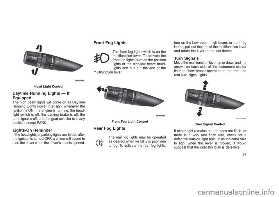
Front Fog Lights
The front fog light switch is on the
multifunction lever. To activate the
front fog lights, turn on the position
lights or the high/low beam head-
lights and pull out the end of the
multifunction lever.
Rear Fog Lights
The rear fog lights may be operated
as desired when visibility is poor due
to fog. To activate the rear fog lights,turn on the Low beam, high beam, or front fog
lamps, pull out the end of the multifunction lever
and rotate the lever to the last detent.
Turn SignalsMove the multifunction lever up or down and the
arrows on each side of the instrument cluster
flash to show proper operation of the front and
rear turn signal lights.
If either light remains on and does not flash, or
there is a very fast flash rate, check for a
defective outside light bulb. If an indicator fails
to light when the lever is moved, it would
suggest that the indicator bulb is defective.
Head Light Control
Front Fog Light ControlTurn Signal Control
97
Page 107 of 332
WARNING!(Continued)
to go faster than you want. You could lose
control and have an accident. Always leave
the system OFF when you are not using it.
To Set A Desired SpeedTurn the Electronic Speed Control ON. When
the vehicle has reached the desired speed,
push the SET (-) button and release. Release
the accelerator and the vehicle will operate at
the selected speed.
NOTE:
The vehicle should be traveling at a steady
speed and on level ground before pushing
the SET (-) button.
To DeactivateA soft tap on the brake pedal, pushing the
CANCEL button, normal braking or pressing the
clutch pedal while slowing the vehicle will deac-
tivate Electronic Speed Control without erasing
the set speed memory. Pushing the ON/OFF
button or turning the ignition switch OFF erases
the set speed memory.
To Resume SpeedTo resume a previously set speed, push the
RES (+) button and release. Resume can be
used at any speed above 20 mph (32 km/h).
To Vary The Speed SettingTo Increase Speed
When the Electronic Speed Control is set, you
can increase speed by pushing the RES (+)
button.
The drivers preferred units can be selected
through the instrument panel settings if
equipped. Refer to “Understanding Your Instru-
ment Panel” for more information. The speed
increment shown is dependant on the chosen
speed unit of U.S. (mph) or Metric (km/h):
U.S. Speed (mph)
•Pushing the RES (+) button once will result in
a 1 mph increase in set speed. Each subse-
quent tap of the button results in an increase
of 1 mph.•If the button is continually pushed, the set
speed will continue to increase until the but-
ton is released, then the new set speed will
be established.
Metric Speed (km/h)
•Pushing the RES (+) button once will result in
a 1 km/h increase in set speed. Each subse-
quent tap of the button results in an increase
of 1 km/h.
•If the button is continually pushed, the set
speed will continue to increase until the but-
ton is released, then the new set speed will
be established.
To Decrease Speed
When the Electronic Speed Control is set, you
can decrease speed by pushing the SET (-)
button.
The drivers preferred units can be selected
through the instrument panel settings if
equipped. Refer to “Understanding Your Instru-
ment Panel” for more information. The speed
decrement shown is dependant on the chosen
speed unit of U.S. (mph) or Metric (km/h):
103
Page 109 of 332
If your vehicle is equipped with the Camera
Delay feature and it is turned On, the rear
camera image will be displayed for up to 10
seconds when the vehicle is shifted out of
REVERSE unless the forward vehicle speed
exceeds 8 mph (13 km/h), the transmission isshifted into"PARK"or the vehicles ignition is
cycled to the OFF position.
Static grid lines will illustrate the width of the
vehicle. The static grid lines will show separate
zones that will help indicate the distance to the
rear of the vehicle. Different colored zonesindicate the distance to the rear of the vehicle.
The following table shows the approximate dis-
tances for each zone:
Zone Distance to the rear of the vehicle
Red 0-1ft(0-30cm)
Yellow 1 ft-3ft(30cm-1m)
Green 3 ft or greater (1 m or greater)
WARNING!
Drivers must be careful when backing up even
when using the ParkView Rear Back Up Cam-
era. Always check carefully behind your vehicle,
and be sure to check for pedestrians, animals,
other vehicles, obstructions, or blind spots be-
fore backing up. You are responsible for the
safety of your surroundings and must continue
to pay attention while backing up. Failure to do
so can result in serious injury or death.
CAUTION!
•To avoid vehicle damage, ParkView should
only be used as a parking aid. The
ParkView camera is unable to view every
obstacle or object in your drive path.
(Continued)
CAUTION!(Continued)
•To avoid vehicle damage, the vehicle must
be driven slowly when using ParkView to
be able to stop in time when an obstacle is
seen. It is recommended that the driver
look frequently over his/her shoulder when
using ParkView.
105
Page 111 of 332
Closing Sunroof — Manual ModeTo close the sunroof, push and hold the switch
in the forward position. Any release of the
switch will stop the movement and the sunroof
will remain in a partially closed condition until
the sunroof switch is pushed again.
Pinch Protect FeatureThis feature will detect an obstruction in the
opening of the sunroof during Express Close
operation. If an obstruction in the path of the
sunroof is detected, the sunroof will automati-
cally retract. Remove the obstruction if this
occurs. Next, push the switch forward and re-
lease to Express Close.
Venting Sunroof — ExpressPush and release the Vent button within one
half second and the sunroof will open to the
vent position. This is called “Express Vent”, and
it will occur regardless of sunroof position. Dur-
ing Express Vent operation, any other actuation
of the switch will stop the sunroof.
Sunshade OperationThe sunshade can be opened manually. How-
ever, the sunshade will open automatically as
the sunroof opens.
NOTE:
The sunshade cannot be closed if the sun-
roof is open.
Wind BuffetingWind buffeting can be described as the percep-
tion of pressure on the ears or a helicopter-type
sound in the ears. Your vehicle may exhibit wind
buffeting with the windows down, or the sunroof
(if equipped) in certain open or partially open
positions. This is a normal occurrence and can
be minimized. If the buffeting occurs with the
rear windows open, open the front and rear
windows together to minimize the buffeting. If
the buffeting occurs with the sunroof open,
adjust the sunroof opening to minimize the
buffeting or open any window.
Sunroof MaintenanceUse only a non-abrasive cleaner and a soft
cloth to clean the glass panel.
Ignition Off OperationFor Vehicles Not Equipped With The Elec-
tronic Vehicle Information Center (EVIC)
The power sunroof switch will remain active for
45 seconds after the ignition switch is turned to
the LOCK position. Opening either front door
will cancel this feature.
For Vehicles Equipped With The EVIC
The power sunroof switch will remain active for
up to approximately ten minutes after the igni-
tion switch is turned to the LOCK position.
Opening either front door will cancel this fea-
ture.
107
Page 112 of 332
ELECTRICAL POWER
OUTLETS
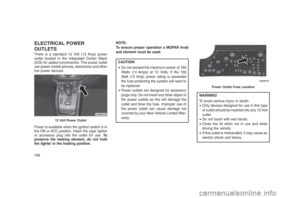
There is a standard 12 Volt (13 Amp) power
outlet located in the Integrated Center Stack
(ICS) for added convenience. This power outlet
can power mobile phones, electronics and other
low power devices.
Power is available when the ignition switch is in
the ON or ACC position. Insert the cigar lighter
or accessory plug into the outlet for use.To
preserve the heating element, do not hold
the lighter in the heating position.NOTE:
To ensure proper operation a MOPAR knob
and element must be used.
CAUTION!
•Do not exceed the maximum power of 160
Watts (13 Amps) at 12 Volts. If the 160
Watt (13 Amp) power rating is exceeded
the fuse protecting the system will need to
be replaced.
•Power outlets are designed for accessory
plugs only. Do not insert any other object in
the power outlets as this will damage the
outlet and blow the fuse. Improper use of
the power outlet can cause damage not
covered by your New Vehicle Limited War-
ranty.
WARNING!
To avoid serious injury or death:
•Only devices designed for use in this type
of outlet should be inserted into any 12 Volt
outlet.
•Do not touch with wet hands.
•Close the lid when not in use and while
driving the vehicle.
•If this outlet is mishandled, it may cause an
electric shock and failure.
12 Volt Power Outlet
Power Outlet Fuse Location
108
Page 118 of 332
Rotate the center portion of the
lever past the first detent to acti-
vate the rear washer. The washer
pump and the wiper will continue to
operate as long as the switch is
held (for a maximum of 10 seconds). Upon
release, the wiper will continue to cycle two
times before returning to the set position.
If the rear wiper is operating when the ignition is
turned OFF, the wiper will automatically return
to the “park” position if power accessory delay is
active. Power accessory delay can be cancelled
by opening the door, if this happens the rear
wiper will stop at its current position and will not
go to “park”.
Rear Window Defroster
The rear window defroster button is
located on the climate controls mode
control knob. Push the button to turn
on the rear window defroster and the
heated outside mirrors (if equipped). An indica-
tor in the button will illuminate when the rear
window defroster is on. The rear window de-
froster automatically turns off after approxi-mately 10 minutes. For an additional five min-
utes of operation, push the button a second
time.
NOTE:
To prevent excessive battery drain, use the
rear window defroster only when the engine
is operating.
CAUTION!
Failure to follow these cautions can cause
damage to the heating elements:
•Use care when washing the inside of the
rear window. Do not use abrasive window
cleaners on the interior surface of the
window. Use a soft cloth and a mild wash-
ing solution, wiping parallel to the heating
elements. Labels can be peeled off after
soaking with warm water.
•Do not use scrapers, sharp instruments, or
abrasive window cleaners on the interior
surface of the window.
•Keep all objects a safe distance from the
window.
ROOF LUGGAGE RACK — IF
EQUIPPED
The crossbars and siderails are designed to
carry the cargo on vehicles equipped with a
luggage rack. The load must not exceed 150 lbs
(68 kg), and should be uniformly distributed
over the luggage rack crossbars.
NOTE:
If not equipped with crossbars, your autho-
rized dealer can order and install MOPAR
crossbars built specifically for this roof rack
system.
Distribute cargo weight evenly on the luggage
rack crossbars. The luggage rack does not
increase the total load carrying capacity of the
vehicle. Be sure the total load of cargo inside
the vehicle plus that on the external rack does
not exceed the maximum vehicle load capacity.
The crossbars must also be secured in one of
the seven detent positions marked with an
arrow on the siderails to prevent movement. To
move the crossbars, loosen the thumb screws
located at the upper edge of each crossbar
approximately eight turns, then move the cross-
11 4
Page 126 of 332
NOTE:
Some of the above warnings will be dis-
played in the Electronic Vehicle Information
Center Display Area located in the instru-
ment cluster.
Refer to ”Electronic Vehicle Information Center
(EVIC) — If Equipped” in this section for further
information.
LoW tirE
When the appropriate condition exists, the
odometer display will toggle between LoW and
tirE for three cycles.
gASCAP
If the vehicle diagnostic system determines that
the fuel filler cap is loose, improperly installed,
or damaged, a “gASCAP” message will display
in the odometer display area. Tighten the fuel
filler cap properly and push the STEP button on
the steering wheel to turn off the message. If the
problem continues, the message will appear the
next time the vehicle is started.noFUSE
If the vehicle diagnostic system determines that
the Ignition Off Draw (IOD) fuse is improperly
installed, or damaged, a “noFUSE” message
will display in the odometer display area. Refer
to “Fuses” in “Maintaining Your Vehicle” for
further information on fuses and fuse locations.
CHAngE OIL
Your vehicle is equipped with an engine oil
change indicator system. The odometer display
will toggle betweenCHAngEandOilfor ap-
proximately 12 seconds, after a single chime
has sounded, to indicate the next scheduled oil
change interval. The engine oil change indicator
system is duty cycle-based, which means the
engine oil change interval may fluctuate depen-
dent upon your personal driving style.
5. Fuel Gauge
•The pointer shows the level of fuel in the
fuel tank when the ignition is placed in the
ON/RUN position.•The fuel pump symbol points to the
side of the vehicle where the fuel door is
located.
WARNING AND INDICATOR
LIGHTS
IMPORTANT:The warning / indicator lights
switch on in the instrument panel together with
a dedicated message and/or acoustic signal
when applicable. These indications are indica-
tive and precautionary and as such must not be
considered as exhaustive and/or alternative to
the information contained in the Owner’s
Manual, which you are advised to read carefully
in all cases. Always refer to the information in
this chapter in the event of a failure indication.
All active telltales will display first if applicable.
The system check menu may appear different
based upon equipment options and current
vehicle status. Some telltales are optional and
may not appear.
122
Page 127 of 332
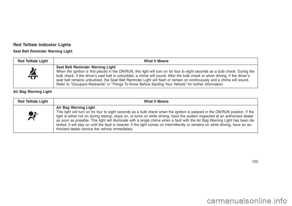
Red Telltale Indicator Lights
Seat Belt Reminder Warning Light
Red Telltale Light What It Means
Seat Belt Reminder Warning Light
When the ignition is first placed in the ON/RUN, this light will turn on for four to eight seconds as a bulb check. During the
bulb check, if the driver’s seat belt is unbuckled, a chime will sound. After the bulb check or when driving, if the driver’s
seat belt remains unbuckled, the Seat Belt Reminder Light will flash or remain on continuously and a chime will sound.
Refer to “Occupant Restraints” in “Things To Know Before Starting Your Vehicle” for further information.
Air Bag Warning Light
Red Telltale Light What It Means
Air Bag Warning Light
This light will turn on for four to eight seconds as a bulb check when the ignition is palaced in the ON/RUN position. If the
light is either not on during startup, stays on, or turns on while driving, have the system inspected at an authorized dealer
as soon as possible. This light will illuminate with a single chime when a fault with the Air Bag Warning Light has been de-
tected, it will stay on until the fault is cleared. If the light comes on intermittently or remains on while driving, have an au-
thorized dealer service the vehicle immediately.
123
Page 129 of 332
WARNING!
Driving a vehicle with the red brake light on is
dangerous. Part of the brake system may
have failed. It will take longer to stop the
vehicle. You could have a collision. Have the
vehicle checked immediately.
Vehicles equipped with the Anti-Lock Brake
System (ABS) are also equipped with ElectronicBrake Force Distribution (EBD). In the event of
an EBD failure, the Brake Warning Light will turn
on along with the ABS Light. Immediate repair
to the ABS system is required.
Operation of the Brake Warning Light can be
checked by turning the ignition switch from the
OFF position to the ON/RUN position. The light
should illuminate for approximately two sec-
onds. The light should then turn off unless the
parking brake is applied or a brake fault isdetected. If the light does not illuminate, have
the light inspected by an authorized dealer.
The light also will turn on when the parking
brake is applied with the ignition switch in the
ON/RUN position.
NOTE:
This light shows only that the parking brake
is applied. It does not show the degree of
brake application.
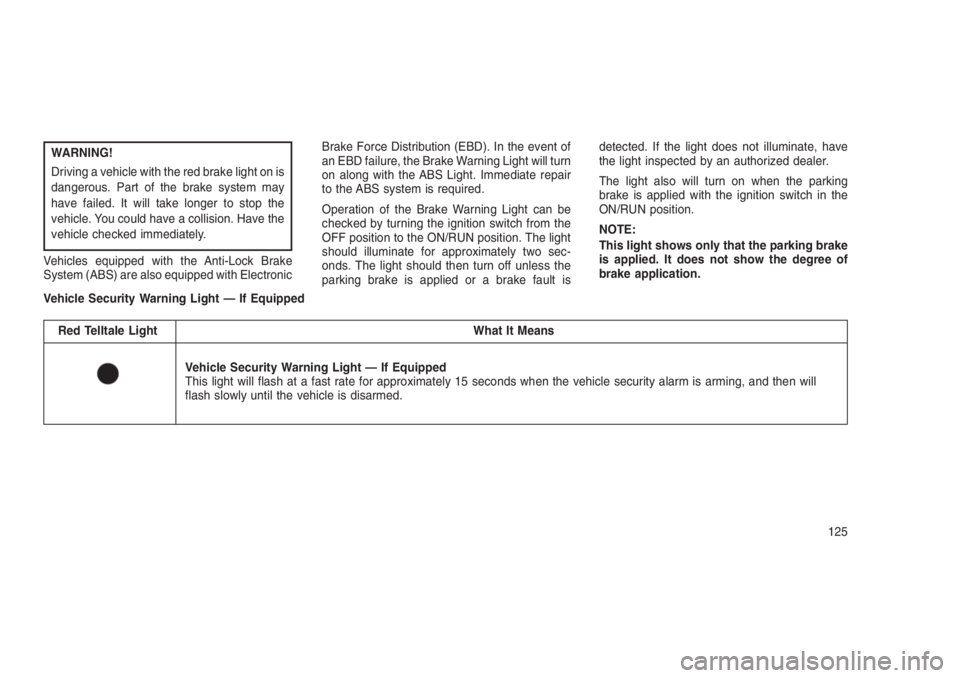
Vehicle Security Warning Light — If Equipped
Red Telltale Light What It Means
Vehicle Security Warning Light — If Equipped
This light will flash at a fast rate for approximately 15 seconds when the vehicle security alarm is arming, and then will
flash slowly until the vehicle is disarmed.
125