maintenance JEEP PATRIOT 2021 Owner handbook (in English)
[x] Cancel search | Manufacturer: JEEP, Model Year: 2021, Model line: PATRIOT, Model: JEEP PATRIOT 2021Pages: 332, PDF Size: 1.99 MB
Page 154 of 332
If you push the switch up or down twice, it plays
the second track; three times, it will play the
third, etc.
The center button on the left side rocker switch
has no function for a single-disc CD player.
However, when a multiple-disc CD player is
equipped on the vehicle, the center button will
select the next available CD in the player.
CD/DVD DISC MAINTENANCE
To keep a CD/DVD in good condition, take the
following precautions:
1. Handle the disc by its edge; avoid touching
the surface.
2. If the disc is stained, clean the surface with a
soft cloth, wiping from center to edge.
3. Do not apply paper or tape to the disc; avoid
scratching the disc.
4. Do not use solvents such as benzene, thin-
ner, cleaners, or anti-static sprays.
5. Store the disc in its case after playing.
6. Do not expose the disc to direct sunlight.7. Do not store the disc where temperatures
may become too high.
NOTE:
If you experience difficulty in playing a par-
ticular disc, it may be damaged (e.g.,
scratched, reflective coating removed, a
hair, moisture or dew on the disc) oversized,
or have protection encoding. Try a known
good disc before considering disc player
service.
RADIO OPERATION AND
MOBILE DEVICES
Under certain conditions, an “on” mobile device
in your vehicle can cause erratic or noisy per-
formance from your radio. This condition may
be lessened or eliminated by relocating the
mobile device antenna. This condition is not
harmful to the radio. If your radio performance
does not satisfactorily “clear” by the reposition-
ing of the antenna, it is recommended that the
radio volume be turned down or off during
mobile device operation when not using
Uconnect (if equipped).
CLIMATE CONTROLS
The air conditioning and heating system is
designed to make you comfortable in all types
of weather.
Manual Heating And Air
Conditioning
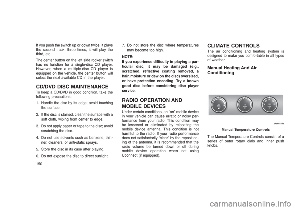
The Manual Temperature Controls consist of a
series of outer rotary dials and inner push
knobs.
Manual Temperature Controls
150
Page 162 of 332
Summer Operation
The engine cooling system must be protected
with a high-quality antifreeze coolant to provide
proper corrosion protection and to protect
against engine overheating. A solution of 50%
OAT (Organic Additive Technology) coolant that
meets the requirements of FCA Material Stan-
dard MS.90032 and 50% water is recom-
mended. Refer to “Maintenance Procedures” in
“Maintaining Your Vehicle” for proper coolant
selection.
Winter Operation
Use of the air Recirculation Mode during winter
months is not recommended because it may
cause window fogging.
Vacation Storage
Anytime you store your vehicle, or keep it out of
service (i.e., vacation) for two weeks or more,
run the air conditioning system at idle for about
five minutes in the fresh air and high blower
settings. This will ensure adequate system lu-
brication to minimize the possibility of compres-
sor damage when the system is started again.Window Fogging
Interior fogging on the windshield can be quickly
removed by turning the mode selector to De-
frost. The Defrost/Floor mode can be used to
maintain a clear windshield and provide suffi-
cient heating. If side window fogging becomes a
problem, increase blower speed. Vehicle win-
dows tend to fog on the inside in mild but rainy
or humid weather.
NOTE:
Recirculate without A/C should not be used
for long periods as fogging may occur.
Side Window Demisters
A side window demister outlet is located at each
end of the instrument panel. These non-
adjustable outlets direct air toward the side
windows when the system is in the FLOOR,
MIX, or DEFROST mode. The air is directed at
the area of the windows through which you view
the outside mirrors.Outside Air Intake
Make sure the air intake, located directly in front
of the windshield, is free of obstructions such as
leaves. Leaves collected in the air intake may
reduce airflow, and if they enter the plenum,
they could plug the water drains. In winter
months, make sure the air intake is clear of ice,
slush, and snow.
A/C Air Filter — If Equipped
The A/C Filter prevents most dust and pollen
from entering the cabin. The filter acts on air
coming from outside the vehicle and recircu-
lated air within the passenger compartment.
Refer to “Maintenance Procedures” in “Main-
taining Your Vehicle” for A/C Air Filter service
information or see your authorized dealer for
service. Refer to “Maintenance Schedules” in
“Maintaining Your Vehicle” for filter service inter-
vals.
158
Page 205 of 332
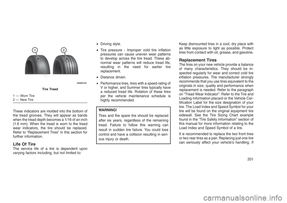
These indicators are molded into the bottom of
the tread grooves. They will appear as bands
when the tread depth becomes a 1/16 of an inch
(1.6 mm). When the tread is worn to the tread
wear indicators, the tire should be replaced.
Refer to “Replacement Tires” in this section for
further information.
Life Of TireThe service life of a tire is dependent upon
varying factors including, but not limited to:•Driving style.
•Tire pressure - Improper cold tire inflation
pressures can cause uneven wear patterns
to develop across the tire tread. These ab-
normal wear patterns will reduce tread life,
resulting in the need for earlier tire
replacement.
•Distance driven.
•Performance tires, tires with a speed rating of
V or higher, and Summer tires typically have
a reduced tread life. Rotation of these tires
per the vehicle maintenance schedule is
highly recommended.
WARNING!
Tires and the spare tire should be replaced
after six years, regardless of the remaining
tread. Failure to follow this warning can
result in sudden tire failure. You could lose
control and have a collision resulting in seri-
ous injury or death.Keep dismounted tires in a cool, dry place with
as little exposure to light as possible. Protect
tires from contact with oil, grease, and gasoline.
Replacement TiresThe tires on your new vehicle provide a balance
of many characteristics. They should be in-
spected regularly for wear and correct cold tire
inflation pressures. The manufacturer strongly
recommends that you use tires equivalent to the
originals in size, quality and performance when
replacement is needed. Refer to the paragraph
on “Tread Wear Indicator”. Refer to the Tire and
Loading Information placard or the Vehicle Cer-
tification Label for the size designation of your
tire. The Load Index and Speed Symbol for your
tire will be found on the original equipment tire
sidewall. See the Tire Sizing Chart example
found in the “Tire Safety Information” section of
this manual for more information relating to the
Load Index and Speed Symbol of a tire.
It is recommended to replace the two front tires
or two rear tires as a pair. Replacing just one tire
can seriously affect your vehicle’s handling. If
Tire Tread
1 — Worn Tire
2 — New Tire
201
Page 207 of 332
CAUTION!
To avoid damage to your vehicle or tires,
observe the following precautions:
•Because of restricted traction device clear-
ance between tires and other suspension
components, it is important that only trac-
tion devices in good condition are used.
Broken devices can cause serious dam-
age. Stop the vehicle immediately if noise
occurs that could indicate device break-
age. Remove the damaged parts of the
device before further use.
•Install device as tightly as possible and
then retighten after driving about ½ mile
(0.8 km).
•Do not exceed 30 mph (48 km/h).
•Drive cautiously and avoid severe turns
and large bumps, especially with a loaded
vehicle.
•Do not drive for a prolonged period on dry
pavement.
(Continued)
CAUTION!(Continued)
•Observe the traction device manufactur-
er’s instructions on the method of installa-
tion, operating speed, and conditions for
use. Always use the suggested operating
speed of the device manufacturer’s if it is
less than 30 mph (48 km/h).
•Do not use traction devices on a compact
spare tire.
TIRE ROTATION
RECOMMENDATIONS
The tires on the front and rear of your vehicle
operate at different loads and perform different
steering, driving, and braking functions. For
these reasons, they wear at unequal rates.
These effects can be reduced by timely rotation
of tires. The benefits of rotation are especially
worthwhile with aggressive tread designs such
as those on all season type tires. Rotation will
increase tread life, help to maintain mud, snow
and wet traction levels, and contribute to a
smooth, quiet ride.Refer to the “Maintenance Schedule” for the
proper maintenance intervals. The reasons for
any rapid or unusual wear should be corrected
prior to rotation being performed.
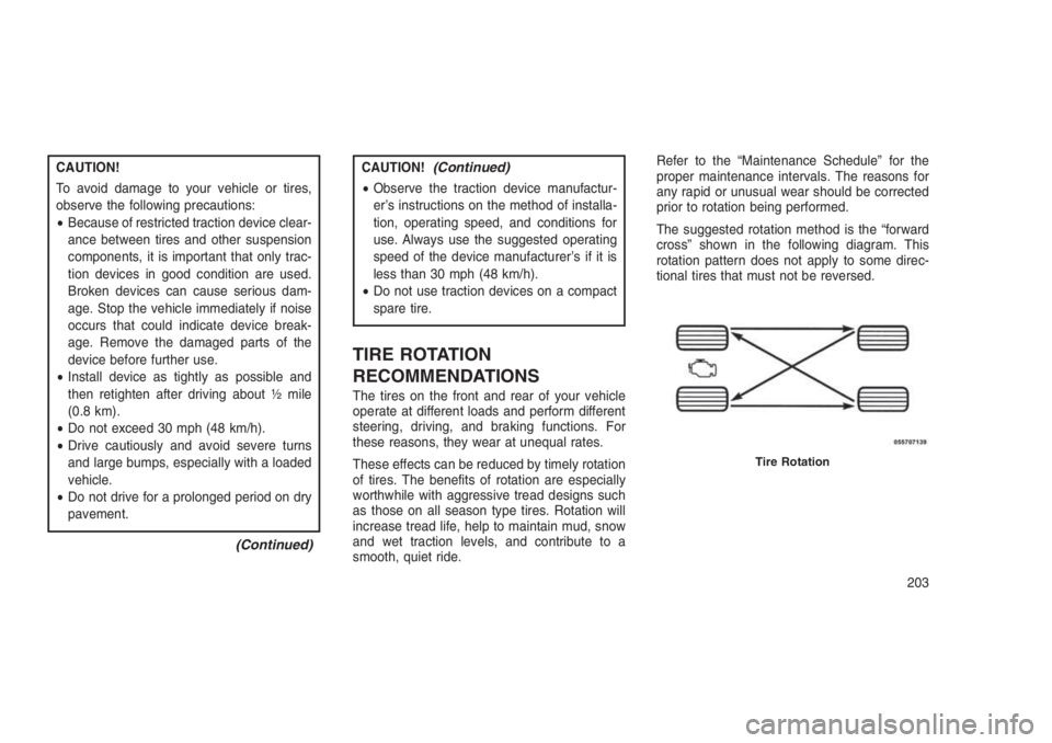
The suggested rotation method is the “forward
cross” shown in the following diagram. This
rotation pattern does not apply to some direc-
tional tires that must not be reversed.
Tire Rotation
203
Page 209 of 332
CAUTION!
•The TPMS has been optimized for the
original equipment tires and wheels. TPMS
pressures and warning have been estab-
lished for the tire size equipped on your
vehicle. Undesirable system operation or
sensor damage may result when using
replacement equipment that is not of the
same size, type, and/or style. Aftermarket
wheels can cause sensor damage.
•Using aftermarket tire sealants may cause
the Tire Pressure Monitoring System
(TPMS) sensor to become inoperable. Af-
ter using an aftermarket tire sealant it is
recommended that you take your vehicle
to an authorized dealership to have your
sensor function checked.
•After inspecting or adjusting the tire pres-
sure always reinstall the valve stem cap.
This will prevent moisture and dirt from
entering the valve stem, which could dam-
age the TPMS sensor.NOTE:
•The TPMS is not intended to replace nor-
mal tire care and maintenance or to pro-
vide warning of a tire failure or condition.
•The TPMS should not be used as a tire
pressure gauge while adjusting your tire
pressure.
•Driving on a significantly under-inflated
tire causes the tire to overheat and can
lead to tire failure. Under-inflation also
reduces fuel efficiency and tire tread life,
and may affect the vehicle’s handling and
stopping ability.
•The TPMS is not a substitute for proper
tire maintenance, and it is the driver’s
responsibility to maintain correct tire
pressure using an accurate tire gauge,
even if under-inflation has not reached
the level to trigger illumination of the Tire
Pressure Monitoring Telltale Light.
•Seasonal temperature changes will affect
tire pressure, and the TPMS will monitor
the actual tire pressure in the tire.Base System
This is the TPMS warning indicator
located in the instrument cluster.
The TPMS uses wireless technology with wheel
rim mounted electronic sensors to monitor tire
pressure levels. Sensors, mounted to each
wheel as part of the valve stem, transmit tire
pressure readings to the Receiver Module.
NOTE:
It is particularly important for you to check
the tire pressure in all of the tires on your
vehicle regularly and to maintain the proper
pressure.
The TPMS consists of the following compo-
nents:
•Receiver Module.
•Four Tire Pressure Monitoring Sensors.
•Tire Pressure Monitoring Telltale Light.
205
Page 216 of 332
WARNING!(Continued)
•Guard against carbon monoxide with
proper maintenance. Have the exhaust
system inspected every time the vehicle is
raised. Have any abnormal conditions re-
paired promptly. Until repaired, drive with
all side windows fully open.
•Keep the liftgate closed when driving your
vehicle to prevent carbon monoxide and
other poisonous exhaust gases from en-
tering the vehicle.
ADDING FUEL
Locking Fuel Filler Cap (Gas Cap)The locking gas cap is inside the fuel filler door,
on the left side of the vehicle. If the gas cap is
lost or damaged, be sure the replacement cap
is for use with this vehicle.
1. Turn off the engine.2. Insert the ignition key into the fuel cap and
turn the key one-quarter turn to the right,
then rotate the fuel cap to the left to remove.
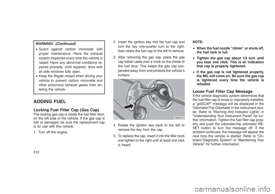
3. After removing the gas cap, place the gas
cap tether cable over a hook on the inside of
the fuel door. This keeps the gas cap sus-
pended away from and protects the vehicle’s
surface.
4. Rotate the ignition key back to the left to
remove the key from the cap.
5. To replace the cap, insert it into the filler neck
and tighten to the right until at least one click
is heard.NOTE:
•When the fuel nozzle “clicks” or shuts off,
the fuel tank is full.
•Tighten the gas cap about 1/4 turn until
you hear one click. This is an indication
that cap is properly tightened.
•If the gas cap is not tightened properly,
the MIL will come on. Be sure the gas cap
is tightened every time the vehicle is
refueled.
Loose Fuel Filler Cap MessageIf the vehicle diagnostic system determines that
the fuel filler cap is loose or improperly installed,
a “gASCAP” message will be displayed in the
Odometer/Trip Odometer in the instrument clus-
ter. Refer to “Warning And Indicator Lights” in
“Understanding Your Instrument Panel” for fur-
ther information. Tighten the fuel filler cap prop-
erly and push the odometer/trip odometer RE-
SET button to turn the message off. If the
problem continues, the message will appear the
next time the vehicle is started. Refer to “On-
board Diagnostic System” in “Maintaining Your
Vehicle” for further information.
212
Page 226 of 332
Towing TipsBefore setting out on a trip, practice turning,
stopping and backing the trailer in an area away
from heavy traffic.
Manual Transmission — If Equipped
If using a manual transmission vehicle for trailer
towing, all starts must be in first gear to avoid
excessive clutch slippage.
Automatic Transmission — If Equipped
The DRIVE range can be selected when towing.
However, if frequent shifting or changes in
engine speed occur while in DRIVE, use the
AutoStick shift control to manually select a
lower gear ratio.
NOTE:
Using a lower gear ratio while operating the
vehicle under heavy loading conditions, will
improve performance and extend transmis-
sion life by reducing excessive shifting and
heat buildup. This action will also provide
better engine braking.
If you REGULARLY tow a trailer for more than
45 minutes of continuous operation, then
change the transmission fluid and filter asspecified for"police, taxi, fleet, or frequent
trailer towing."Refer to the “Maintenance
Schedule” for the proper maintenance intervals.
AutoStick
•When using the AutoStick shift control, select
the highest gear that allows for adequate
performance and avoids frequent downshifts.
For example, choose"4"if the desired speed
can be maintained. Choose"3"or"2"if
needed to maintain the desired speed.
•To prevent excess heat generation, avoid
continuous driving at high RPM. Reduce
vehicle speed as necessary to avoid ex-
tended driving at high RPM. Return to a
higher gear or vehicle speed when grade and
road conditions allow.
Electronic Speed Control — If Equipped
•Do not use in hilly terrain or with heavy loads.
•When using the speed control, if you experi-
ence speed drops greater than 10 mph
(16 km/h), disengage until you can get back
to cruising speed.•Use speed control in flat terrain and with light
loads to maximize fuel efficiency.
Cooling System
To reduce potential for engine and transmission
overheating, take the following actions:
City Driving
When stopped for short periods of time, shift the
transmission into NEUTRAL and increase en-
gine idle speed.
Highway Driving
Reduce speed.
Air Conditioning
Turn off temporarily.
222
Page 255 of 332
7
MAINTAINING YOUR VEHICLE
•ENGINE COMPARTMENT — 2.0L . . . . . . . . . . . . .. . . . . .253
•ENGINE COMPARTMENT — 2.4L . . . . . . . . . . . . .. . . . . .254
•ONBOARD DIAGNOSTIC SYSTEM — OBD II . . ..........255
•Onboard Diagnostic System (OBD II) Cybersecurity.......255
•Loose Fuel Filler Cap Message...................256
•REPLACEMENT PARTS . . . . . . . . . . . . . . . . . . . . . . . . .256
•MAINTENANCE PROCEDURES . . . . . . . . . . . . . . ......256
•Engine Oil................................256
•Engine Oil Filter............................258
•Engine Air Cleaner Filter.......................258
•Maintenance-Free Battery.......................258
•Air Conditioner Maintenance.....................259
•Body Lubrication............................261
•Windshield Wiper Blades.......................261
•Adding Washer Fluid.........................261
•Exhaust System............................262
•Cooling System............................263
•Brake System..............................266
•Automatic Transmission (6-Speed) — If Equipped........267
251
Page 260 of 332
Loose Fuel Filler Cap MessageAfter fuel is added, the vehicle diagnostic sys-
tem can determine if the fuel filler cap is possi-
bly loose or improperly installed. A “gASCAP”
message will be displayed in the instrument
cluster. Tighten the gas cap until a “clicking”
sound is heard. This is an indication that the gas
cap is properly tightened. Push the trip odom-
eter RESET button to turn off the message. If
the problem persists, the message will appear
the next time the vehicle is started. This might
indicate a damaged cap. If the problem is
detected twice in a row, the system will turn on
the MIL. Resolving the problem will turn the MIL
light off.
REPLACEMENT PARTS
Use of genuine MOPAR parts for normal/
scheduled maintenance and repairs is highly
recommended to ensure the designed perfor-
mance. Damage or failures caused by the use
of non-MOPAR parts for maintenance and re-
pairs will not be covered by the New Vehicle
Limited Warranty.
MAINTENANCE PROCEDURES
The pages that follow contain therequired
maintenance services determined by the engi-
neers who designed your vehicle.
Besides those maintenance items specified in
the fixed “Maintenance Schedule”, there are
other components which may require servicing
or replacement in the future.
CAUTION!
•Failure to properly maintain your vehicle or
perform repairs and service when neces-
sary could result in more costly repairs,
damage to other components or negatively
impact vehicle performance. Immediately
have potential malfunctions examined by
an authorized dealer or qualified repair
center.
(Continued)
CAUTION!(Continued)
•Your vehicle has been built with improved
fluids that protect the performance and
durability of your vehicle and also allow
extended maintenance intervals. Do not
use chemical flushes in these components
as the chemicals can damage your engine,
transmission, or air conditioning. Such
damage is not covered by the New Vehicle
Limited Warranty. If a flush is needed
because of component malfunction, use
only the specified fluid for the flushing
procedure.
Engine Oil
Checking Oil Level
To assure proper engine lubrication, the engine
oil must be maintained at the correct level.
Check the oil level at regular intervals, such as
every fuel stop.
The best time to check the engine oil level is
about five minutes after a fully warmed engine is
shut off. Do not check oil level before starting
256
Page 261 of 332
the engine after it has sat overnight. Checking
engine oil level when the engine is cold will give
you an incorrect reading.
Checking the oil while the vehicle is on level
ground and only when the engine is hot, will
improve the accuracy of the oil level readings.
Maintain the oil level between the range mark-
ings on the dipstick. The range markings will
consist of a crosshatch zone that says SAFE or
a crosshatch zone that says MIN at the low end
of the range and MAX at the high end of the
range. Adding one quart of oil when the reading
is at the low end of the indicated range will result
in the oil level at the full end of the indicator
range.
CAUTION!
Do not overfill the engine. Overfilling the
engine will cause oil aeration, which can lead
to loss of oil pressure and an increase in oil
temperature. This could damage your en-
gine. Also, be sure the oil fill cap is replaced
and tightened after adding oil.Change Engine Oil – All Engines
Refer to the “Maintenance Schedule” for the
proper maintenance intervals.
Engine Oil Selection
For best performance and maximum protection
under all types of operating conditions, the manu-
facturer only recommends engine oils that are API
certified and meet the requirements of FCA Ma-
terial Standard MS-6395 or ACEA A1/B1.
American Petroleum Institute (API) Engine
Oil Identification Symbol
This symbol means that
the oil has been certified
by the American Petro-
leum Institute (API). The
manufacturer only rec-
ommends API Certified
engine oils.
This symbol certifies 0W-20, 5W-20, 0W-30,
5W-30 and 10W-30 engine oils.
CAUTION!
Do not use chemical flushes in your engine
oil as the chemicals can damage your en-
gine. Such damage is not covered by the
New Vehicle Limited Warranty.
Engine Oil Viscosity (SAE Grade)
MOPAR SAE 5W-20 engine oil is recom-
mended for all operating temperatures. This
engine oil improves low temperature starting
and vehicle fuel economy.
The engine oil filler cap also shows the recom-
mended engine oil viscosity for your engine. For
information on engine oil filler cap location, refer
to “Engine Compartment” in “Maintaining Your
Vehicle” for further information.
NOTE:
MOPAR SAE 5W-30 engine oil approved to
FCA MS-6395 or FCA Material Standard
9.55535-CR1 may be used when SAE 5W-20
engine oil meeting FCA MS-6395 or FCA
Material Standard 9.55535-CR1 is not avail-
able.
257