start stop button JEEP RENEGADE 2014 1.G User Guide
[x] Cancel search | Manufacturer: JEEP, Model Year: 2014, Model line: RENEGADE, Model: JEEP RENEGADE 2014 1.GPages: 212, PDF Size: 17.48 MB
Page 109 of 212

122)Before opening the bonnet, make
sure that the vehicle is switched off and
that the ignition device is in the STOP
position. Follow the indications on the plate
underneath the bonnet. We recommend
that you remove the key from the ignition if
other people remain in the vehicle. The
vehicle should always be left after the key
has been removed or turned to the STOP
position. During refuelling, make sure
that the engine is off (ignition device in the
STOP position).
WARNING
39)If climate comfort is to be favoured, the
Stop/Start system can be deactivated,
for a continuous operation of the climate
control system.
SPEED LIMITER
DESCRIPTION
This device allows the speed of the
vehicle to be limited to values which
can be set by the driver.
The maximum speed can be set both
with vehicle stationary and in motion.
The minimum speed that can be set is
30 km/h.
When the device is active, the vehicle
speed depends on the pressure at
the accelerator pedal, until the set
speed limit is reached.
ACTIVATING THE DEVICE
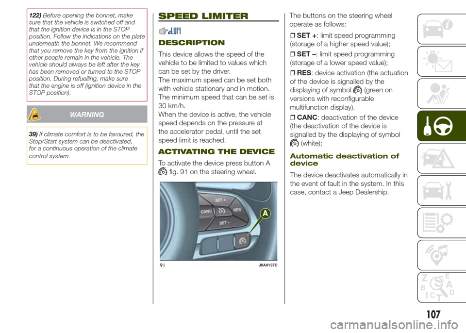
To activate the device press button A
fig. 91 on the steering wheel.The buttons on the steering wheel
operate as follows:
❒SET +: limit speed programming
(storage of a higher speed value);
❒SET –: limit speed programming
(storage of a lower speed value);
❒RES: device activation (the actuation
of the device is signalled by the
displaying of symbol
(green on
versions with reconfigurable
multifunction display).
❒CANC: deactivation of the device
(the deactivation of the device is
signalled by the displaying of symbol
(white);
Automatic deactivation of
device
The device deactivates automatically in
the event of fault in the system. In this
case, contact a Jeep Dealership.
91J0A0137C
107
Page 114 of 212

PARKSENSE
SYSTEM
SENSORS
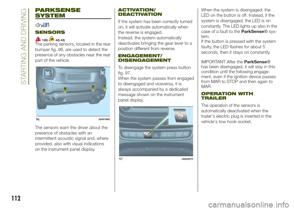
126)42) 43)The parking sensors, located in the rear
bumper fig. 96, are used to detect the
presence of any obstacles near the rear
part of the vehicle.
The sensors warn the driver about the
presence of obstacles with an
intermittent acoustic signal and, where
provided, also with visual indications
on the instrument panel display.
ACTIVATION/
DEACTIVATION
If the system has been correctly turned
on, it will activate automatically when
the reverse is engaged.
Instead, the system automatically
deactivates bringing the gear lever to a
position different from reverse.
ENGAGEMENT/
DISENGAGEMENT
To disengage the system press button
fig. 97.
When the system passes from engaged
to disengaged and viceversa, it is
always accompanied by a dedicated
message shown on the instrument
panel display.When the system is disengaged, the
LED on the button is off. Instead, if the
system is disengaged, the LED is on
constantly. The LED lights up also in the
case of a fault to theParkSense® sys-
tem.
If the button is pressed with the system
faulty, the LED flashes for about 5
seconds, then it stays on constantly.
IMPORTANT After theParkSense®
has been disengaged, it will stay in this
condition until the following engage-
ment, even if the ignition device passes
from MAR to STOP and then again to
MAR.
OPERATION WITH
TRAILER
The operation of the sensors is
automatically deactivated when the
trailer's electric plug is inserted in the
vehicle's tow hook socket.
96J0A0166C
97J0A0227C
112
STARTING AND DRIVING
Page 145 of 212

FUEL CUT-OFF
SYSTEM
This intervenes in the case of an impact
causing:
❒the interruption of the fuel supply with
the engine consequently cutting out;
❒the automatic unlocking of the doors;
❒turning on of the lights inside the
vehicle;
❒deactivation of climate control system
ventilation;
❒switching on of the hazard warning
lights (to deactivate the lights press the
button on the dashboard).
On some versions, the intervention of
the system is indicated by a message
shown on the display. In the same way,
a dedicated message on the display
warns the driver if system operation is
compromised.
IMPORTANT Carefully check the vehicle
for fuel leaks, for instance in the engine
compartment, under the vehicle or
near the tank area. After a collision,
bring the ignition device to STOP to
prevent the battery from running down.
To restore correct operation of the
vehicle, carry out the following
procedure (this procedure must be
started and completed within less than
one minute):❒move the ignition device to MAR;
❒turn on the direction indicators on the
right, then on the left, then again on
the right and again on the left;
❒now deactivate the direction
indicators on the left;
❒bring the ignition device to STOP;
❒move the ignition device to MAR.
160)
WARNING
160)If, after an impact, you smell fuel or
notice leaks from the fuel system, do
not reactivate the system to avoid the risk
of fire.
AUTOMATIC
TRANSMISSION
GEAR LEVER
UNLOCKING
In the event of a fault, to move the gear
lever from P (Park), proceed as follows:
❒stop the engine and engage the
electric parking brake;
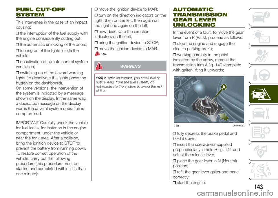
❒working carefully in the point
indicated by the arrow, remove the
transmission trim A fig. 140 (complete
with gaiter) lifting it upwards;
❒fully depress the brake pedal and
hold it down;
❒insert the screwdriver supplied
perpendicularly in hole B fig. 141 and
adjust the release lever;
❒place the gear lever in N (Neutral)
position;
❒refit the gear lever gaiter and panel
correctly;
140J0A0342C
143
❒start the engine.
Page 162 of 212

BATTERY
RECHARGING
IMPORTANT
IMPORTANT After placing the ignition
device to STOP and having closed
the driver side door, wait at least one
minute before disconnecting the
electrical supply from the battery. When
reconnecting the electrical supply to
the battery, make sure that the ignition
device is in the STOP position and
the driver side door is closed.
IMPORTANT Charging should be slow
at a low ampere rating for
approximately 24 hours. Charging for a
longer time may damage the battery.IMPORTANT The cables of the
electrical system must be correctly
reconnected to the battery, i.e. the
positive cable (+) to the positive
terminal and the negative cable (–) to
the negative terminal. The battery
terminals are marked with the positive
(+) and negative (–) symbols, and are
shown on the battery cover. The battery
terminals must also be corrosion-free
and firmly secured to the terminals. If a
"quick-type" battery charger is used
with the battery fitted on the vehicle,
before connecting it disconnect both
cables of the battery itself. Do not use a
"quick-type" battery charger to provide
the starting voltage.
VERSIONS WITHOUT
STOP/START SYSTEM
To recharge, proceed as follows:
❒disconnect the terminal from the
negative battery pole;
❒connect the charger cables to the
battery terminals, observing the polarity;
❒turn on the charger;
❒when it is recharged, turn the charger
off before disconnecting it from the
battery;
❒reconnect the negative battery
terminal.
VERSIONS WITH
STOP/START SYSTEM
To recharge, proceed as follows:
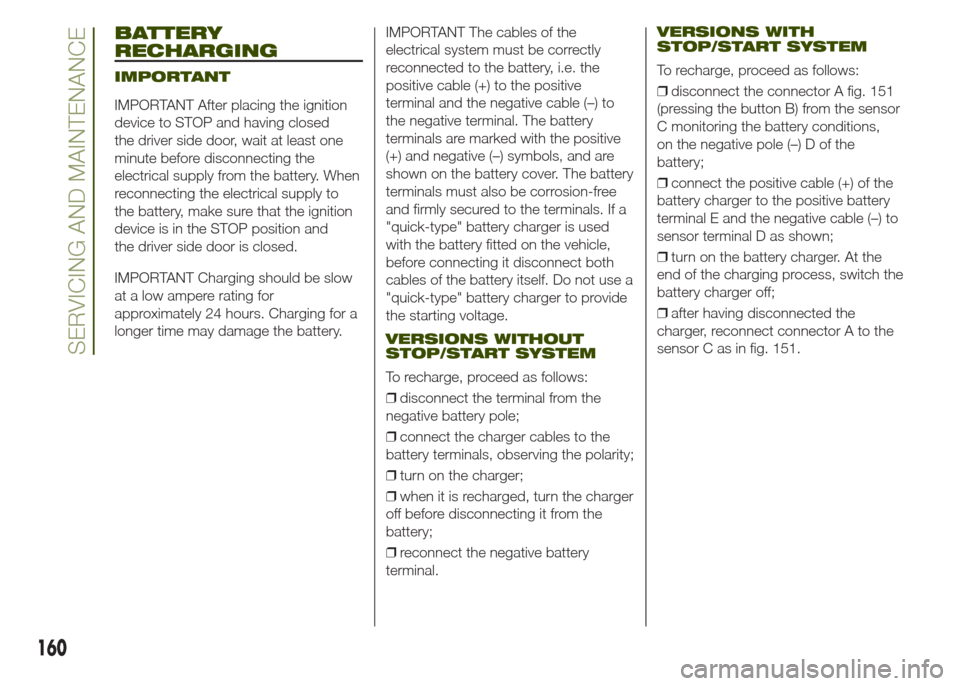
❒disconnect the connector A fig. 151
(pressing the button B) from the sensor
C monitoring the battery conditions,
on the negative pole (–) D of the
battery;
❒connect the positive cable (+) of the
battery charger to the positive battery
terminal E and the negative cable (–) to
sensor terminal D as shown;
❒turn on the battery charger. At the
end of the charging process, switch the
battery charger off;
❒after having disconnected the
charger, reconnect connector A to the
sensor C as in fig. 151.
160
SERVICING AND MAINTENANCE