engine JEEP RENEGADE 2014 1.G Service Manual
[x] Cancel search | Manufacturer: JEEP, Model Year: 2014, Model line: RENEGADE, Model: JEEP RENEGADE 2014 1.GPages: 212, PDF Size: 17.48 MB
Page 107 of 212
IMPORTANT In the event of a
temporary failure it is anyway
recommended to contact a Jeep
Dealership as soon as possible.
IGNITION LOCK AND
PARK POSITION
Versions equipped with the Keyless
Enter-N-Go system: this function
requires the gear lever to be positioned
to P (Park) before bringing the ignition
device to position STOP.
Versions equipped with mechanical
key: this function requires the gear
lever to be positioned to P (Park) before
extracting the key from the ignition
device.
If the vehicle battery is flat and the
ignition key is engaged, the latter is
locked in position. To remove the key
manually see paragraph "Automatic
transmission lever unlock" in chapter "In
an emergency".
GEAR ENGAGEMENT
DISABLING SYSTEM
WITHOUT BRAKE PEDAL
PRESSED
This system prevents you from moving
the gear lever from position P (Park) if
the brake pedal has not been previously
depressed.
To bring the gear lever to a position
other than P (Park), the ignition device
must be in position AVV (engine on
or off) and the brake pedal must be
depressed.
WARNING
116)Never use position P instead of the
electric parking brake. When the vehicle is
parked, always engage the electric parking
brake to prevent accidental movements
of the vehicle.
117)If position P is not engaged the
vehicle might move and hurt people.
Before leaving the vehicle make sure that
the gear lever is in position P and the
electric parking brake is engaged.
118)Do not position the gear lever to N,
nor switch off the engine to travel
downhills. This type of driving is dangerous
and reduces the possibility of intervening
in the case of variation of the road traffic or
surface. You risk to lose control of your
vehicle and cause accidents.119)Before moving the gear lever from
position P, bring the ignition device to
position MAR and press the brake pedal.
Otherwise the gear lever might be
damaged.
120)Engage the reverse gear only with
vehicle at a standstill, engine idling and
accelerator completely released.
105
Page 108 of 212
STOP/START
SYSTEM
The Stop/Start system automatically
stops the engine each time the vehicle
is stationary and starts it again when
the driver wants to move off.
In this way, the vehicle efficiency is
increased, by reducing consumption,
dangerous gas emissions and noise
pollution.
121) 122)39)
OPERATING MODES
Engine stopping mode
Versions with manual gearbox
With the vehicle stopped, the engine
stops with gearbox in neutral and
clutch pedal released.
Versions with automatic transmission
With vehicle at a standstill and brake
pedal pressed, the engine switches off
if the gear lever is in a position other
than R.
In the event of stops uphill, the engine
switching off is disabled to activate
the "Hill Start Assist" function (works
only with running engine).
The
warning light on the instrument
panel switches on to signal that the
engine was stopped.
Engine restarting mode
Versions with manual gearbox
To restart the engine, press the clutch
pedal.
If the vehicle does not start pressing the
clutch, place the gear lever in neutral
and repeat the procedure. If the
problem persists, contact a Jeep
Dealership.
Versions with automatic transmission
To restart the engine, release the brake
pedal.
With brake pressed, if the gear lever is
in automatic mode - D (Drive) - the
engine can be restarted moving the
lever to R (Reverse) or N (Neutral)
or "AutoStick".
With brake pressed, if the gear lever is
in "AutoStick" mode, the engine can be
restarted moving the lever to "+" or
"–", or R (Reverse) or N (Neutral).
When the engine has been stopped
automatically, keeping the brake pedal
pressed, the brake can be released
keeping the engine off by quickly
shifting the gear lever to P (Park).
To restart the engine, just move the
lever out of position P.
SYSTEM MANUAL
ACTIVATION/
DEACTIVATION
To activate/deactivate the system
manually, press the
button on the
central tunnel fig. 90.
❒LED off: system deactivated;
❒LED on: system deactivated.
WARNING
121)When replacing the battery, always
contact a Jeep Dealership. The
replacement battery should be of the same
type (HEAVY DUTY) and should have the
same characteristics.
90J0A0134C
106
STARTING AND DRIVING
Page 109 of 212
122)Before opening the bonnet, make
sure that the vehicle is switched off and
that the ignition device is in the STOP
position. Follow the indications on the plate
underneath the bonnet. We recommend
that you remove the key from the ignition if
other people remain in the vehicle. The
vehicle should always be left after the key
has been removed or turned to the STOP
position. During refuelling, make sure
that the engine is off (ignition device in the
STOP position).
WARNING
39)If climate comfort is to be favoured, the
Stop/Start system can be deactivated,
for a continuous operation of the climate
control system.
SPEED LIMITER
DESCRIPTION
This device allows the speed of the
vehicle to be limited to values which
can be set by the driver.
The maximum speed can be set both
with vehicle stationary and in motion.
The minimum speed that can be set is
30 km/h.
When the device is active, the vehicle
speed depends on the pressure at
the accelerator pedal, until the set
speed limit is reached.
ACTIVATING THE DEVICE
To activate the device press button A
fig. 91 on the steering wheel.The buttons on the steering wheel
operate as follows:
❒SET +: limit speed programming
(storage of a higher speed value);
❒SET –: limit speed programming
(storage of a lower speed value);
❒RES: device activation (the actuation
of the device is signalled by the
displaying of symbol
(green on
versions with reconfigurable
multifunction display).
❒CANC: deactivation of the device
(the deactivation of the device is
signalled by the displaying of symbol
(white);
Automatic deactivation of
device
The device deactivates automatically in
the event of fault in the system. In this
case, contact a Jeep Dealership.
91J0A0137C
107
Page 112 of 212
IMPORTANT On some versions,
pressing the button 4WD LOW
it automatically activates the 4WD
LOCK function as well. If the 4WD LOW
button is pressed again, the 4WD
LOCK function will be activated. If,
however, the 4WD LOCK button is
pressed again, both functions will be
deactivated.
IMPORTANT The 4WD LOW function is
recommended for irregular and slippery
terrain only.
4WD LOW MODE
ENGAGEMENT/RELEASE
4WD LOW mode
engagement
With vehicle at a standstill, ignition
device in MAR position or with engine
on, move the gear lever to position
D (Drive), R (Reverse) or N (Neutral) and
press the 4WD LOW button.
On some versions, with mode
engaged, the display shows "4WD
LOW". The LED on theSelec-
Terrain™device may flash until the
end of the engagement.
4WD LOW mode release
The release can occur at any speed
ranging from 0 to 120 km/h.
On some versions, "4WD LOW" on the
display switches off at the end of the
release procedure.
In this case, the LED on the 4WD LOW
button is off.
WARNING
40)The correct operation of the 4WD
function depends on the tyres: all of them
must have the same size, the same type
and the same circumference. The use
of tyres of the wrong size could interfere
with gear changes and damage
transmission components.41)Do not drive at speeds exceeding
those permitted by the conditions of the
road.
94J0A0156C
110
STARTING AND DRIVING
Page 113 of 212
SELEC-TERRAIN
DRIVING MODE
SELECTION
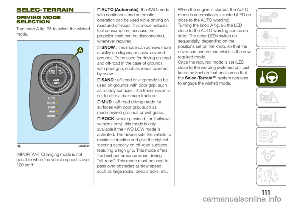
Turn knob A fig. 95 to select the wished
mode.
IMPORTANT Changing mode is not
possible when the vehicle speed is over
120 km/h.❒AUTO (Automatic): the 4WD mode
with continuous and automatic
operation can be used while driving on
road and off-road. This mode reduces
fuel consumption, because the
propeller shaft can be disconnected,
whenever required.
❒SNOW: this mode can achieve more
stability on slippery or snow-covered
grounds. To be used for driving on-road
and off-road in the case of grounds
with poor grip, such as roads covered
by snow.
❒SAND: off-road driving mode to be
used on grounds with poor grip, such
as muddy surfaces. The transmission is
set to offer a maximum traction.
❒MUD: off-road driving mode for
surfaces with poor grip, such as
mud-covered grounds or wet grass.
❒ROCK(where provided, for Trailhawk
versions only): this mode is only
available if the 4WD LOW mode is
activated. The device sets the vehicle to
maximise traction and give the highest
steering capacity on off-road surfaces
featuring a high grip. This mode offers
the best performance when driving
"off-road". This mode must be used to
pass over obstacles at slow speed,
such as large rocks, deep cracks, etc.When the engine is started, the AUTO
mode is automatically selected (LED on
close to the AUTO wording).
Turning the knob A fig. 95 the LED
close to the AUTO wording comes on
solid. The other LEDs switch on
sequentially, depending on the
positions set on the knob, so that the
driver can understand which is the new
required mode.
Once the required mode is set (LED
close to the wording switched on), just
keep the knob in that position so that
theSelec-Terrain™system actuates
to engage the wished mode.
95J0A0153C
111
Page 116 of 212
LANESENSE
SYSTEM (lane
crossing warning)
DESCRIPTION
44) 45) 46) 47) 48) 49)
The LaneSense system makes use of a
camera located on the windscreen to
detect the lane limits and calculate
the position of the vehicle within such
limits, in order to make sure that it
remains inside the lane.
When both limits of the lane are
detected and the vehicle crosses one of
them without the awareness of the
driver (direction indicator off), the
system provides a tactile warning by
applying torque to the steering wheel,
signalling the driver that he must take
an action to remain into the lane.
If the vehicle continues going beyond
the line of the lane without any
intervention from the driver, the
warning light (or the corresponding
graphic icon on the reconfigurable
multifunction display) will be displayed
on the instrument panel to urge the
driver to bring the vehicle back into the
limits of the lane.IMPORTANT The system monitors the
presence of the driver's hands on
the steering wheel. If they are
not detected, the system emits an
acoustic signal and deactivates until it is
reactivated by pressing the dedicated
button.
When one limit of the lane is detected
and the vehicle crosses it (direction
indicator off), warning light
(or the
icon on the reconfigurable multifunction
display) will be displayed on the
instrument panel to urge the driver to
bring the vehicle back into the lane.
In this case, the tactile warning (torque
on the steering wheel) is not provided.
SYSTEM ACTIVATION/
DEACTIVATION
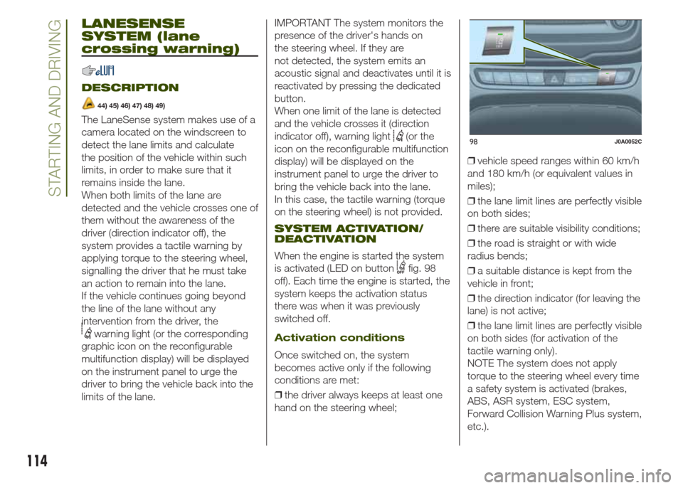
When the engine is started the system
is activated (LED on button
fig. 98
off). Each time the engine is started, the
system keeps the activation status
there was when it was previously
switched off.
Activation conditions
Once switched on, the system
becomes active only if the following
conditions are met:
❒the driver always keeps at least one
hand on the steering wheel;❒vehicle speed ranges within 60 km/h
and 180 km/h (or equivalent values in
miles);
❒the lane limit lines are perfectly visible
on both sides;
❒there are suitable visibility conditions;
❒the road is straight or with wide
radius bends;
❒a suitable distance is kept from the
vehicle in front;
❒the direction indicator (for leaving the
lane) is not active;
❒the lane limit lines are perfectly visible
on both sides (for activation of the
tactile warning only).
NOTE The system does not apply
torque to the steering wheel every time
a safety system is activated (brakes,
ABS, ASR system, ESC system,
Forward Collision Warning Plus system,
etc.).
98J0A0052C
114
STARTING AND DRIVING
Page 122 of 212
To ensure correct operation of the
system, periodically remove all deposits
of dirt which may have accumulated
on the ball head bar and from the
mounting pipe. The lock must only be
treated with graphite.
Periodically lubricate the joints, the
sliding surfaces and the balls with
grease without resin or oil. Lubrication
is also a further corrosion protection.
if the vehicle is washed with high-
pressure jets, the ball head bar must be
removed and the dedicated plug fitted.
The ball head bar must never be
treated with high-pressure jets.
Two keys are supplied together with the
removable ball tow bar. Note down
the four-digit key number and keep it in
a safe place. This number is to be
used for ordering any duplicate keys
that may be required.
IMPORTANT To install a tow hook
contact a Jeep Dealership.
WARNING
128)The ABS with which the vehicle is
equipped will not control the braking
system of the trailer. Particular caution is
therefore required on slippery surfaces.
129)Never modify the braking system of
the vehicle to control the trailer brake. The
trailer braking system must be fully
independent of the vehicle’s hydraulic
system.
REFUELLING THE
VEHICLE
Always stop the engine before
refuelling.
130) 131) 132)
PETROL ENGINES
Only use unleaded petrol with a number
of octanes (R.O.N.) not lower than 95
(EN228 specification).
DIESEL ENGINES
51)Only use Diesel for motor vehicles
(EN590 specification).
When using or parking the vehicle for a
long time in the mountains or cold
areas, it is advisable to refuel using
locally available diesel. In this case, it is
also advisable to keep the tank over
50% full.
REFUELLING
PROCEDURE
The fuel flap is unlocked when the
central door locking system is released,
while it is automatically locked when
the central locking system is applied.
Opening the flap
To refuel proceed as follows:
❒open flap A fig. 102, from the point
shown by the arrow;
120
STARTING AND DRIVING
Page 124 of 212
WARNING
51)The vehicle must only be filled with
diesel fuel for motor vehicles, in
compliance with European Standard EN
590. The use of other products or mixtures
may damage the engine beyond repair
and consequently invalidate the warranty,
due to the damage caused. If you
accidentally refuel with another type of fuel,
do not start the engine, and drain the
tank. If the engine has run, even for a very
short time, you will need to have the entire
fuel supply system emptied in addition to
the tank.
122
STARTING AND DRIVING
Page 128 of 212
CHANGING AN EXTERIOR
LIGHT
Front upper light cluster
(main beam/dipped halogen
headlights)
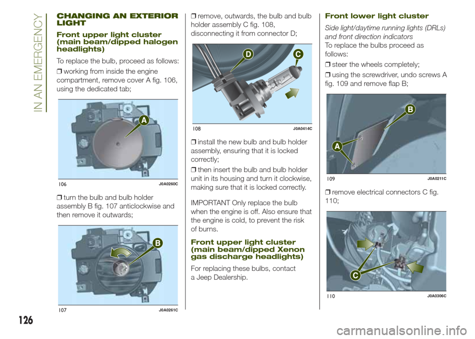
To replace the bulb, proceed as follows:
❒working from inside the engine
compartment, remove cover A fig. 106,
using the dedicated tab;
❒turn the bulb and bulb holder
assembly B fig. 107 anticlockwise and
then remove it outwards;❒remove, outwards, the bulb and bulb
holder assembly C fig. 108,
disconnecting it from connector D;
❒install the new bulb and bulb holder
assembly, ensuring that it is locked
correctly;
❒then insert the bulb and bulb holder
unit in its housing and turn it clockwise,
making sure that it is locked correctly.
IMPORTANT Only replace the bulb
when the engine is off. Also ensure that
the engine is cold, to prevent the risk
of burns.
Front upper light cluster
(main beam/dipped Xenon
gas discharge headlights)
For replacing these bulbs, contact
a Jeep Dealership.
Front lower light cluster
Side light/daytime running lights (DRLs)
and front direction indicators
To replace the bulbs proceed as
follows:
❒steer the wheels completely;
❒using the screwdriver, undo screws A
fig. 109 and remove flap B;
❒remove electrical connectors C fig.
110;
106J0A0260C
107J0A0261C
108J0A0414C
109J0A0211C
110J0A0306C
126
IN AN EMERGENCY
Page 132 of 212
WARNING
133)Before replacing the bulb, wait for the
exhaust ducts to cool down: RISK OF
BURNS!
134)Changes or repairs to the electrical
system carried out incorrectly and without
due consideration for the technical
specifications of the system may lead to
malfunctioning and generate a fire hazard.
135)Halogen bulbs contain pressurised
gas. If they break, glass fragments could fly
everywhere.
WARNING
52)Halogen bulbs must be handled by
holding the metallic part only. Touching the
transparent part of the bulb with your
fingers may reduce the intensity of the
emitted light and even reduce the lifespan
of the bulb. In the case of accidental
contact, rub the lamp with a cloth and
spirit and leave to dry.
REPLACING FUSES
INTRODUCTION
136) 137) 138) 139) 140)
53) 54)
Fuse extracting pliers
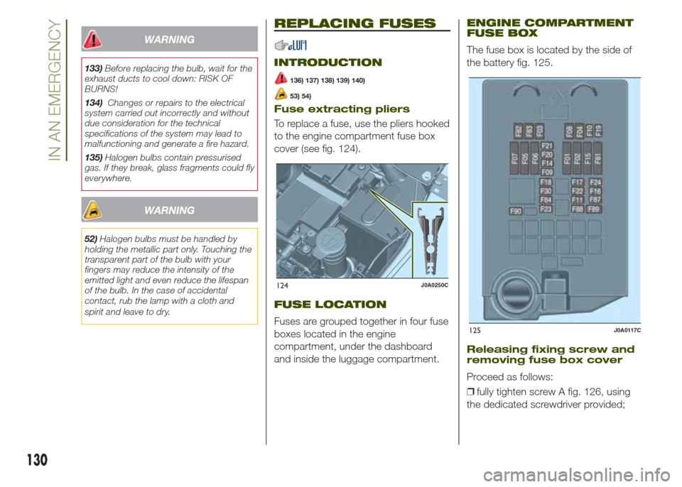
To replace a fuse, use the pliers hooked
to the engine compartment fuse box
cover (see fig. 124).
FUSE LOCATION
Fuses are grouped together in four fuse
boxes located in the engine
compartment, under the dashboard
and inside the luggage compartment.
ENGINE COMPARTMENT
FUSE BOX
The fuse box is located by the side of
the battery fig. 125.
Releasing fixing screw and
removing fuse box cover
Proceed as follows:
❒fully tighten screw A fig. 126, using
the dedicated screwdriver provided;
124J0A0250C
125J0A0117C
130
IN AN EMERGENCY