automatic transmission JEEP RENEGADE 2015 1.G Owner's Manual
[x] Cancel search | Manufacturer: JEEP, Model Year: 2015, Model line: RENEGADE, Model: JEEP RENEGADE 2015 1.GPages: 220, PDF Size: 34.11 MB
Page 178 of 220
6. Once the engine is started, remove the jumper cables in the reverse sequence:
Disconnecting The Jumper Cables
1. Disconnect the negative(-)end of the jumper cable from the engine ground of the
vehicle with the discharged battery.
2. Disconnect the opposite end of the negative(-)jumper cable from the negative(-)
post of the booster battery.
3. Disconnect the positive(+)end of the jumper cable from the positive(+)post of
the booster battery.
4. Disconnect the opposite end of the positive(+)jumper cable from the positive(+)
post of the vehicle with the discharged battery.
If frequent jump-starting is required to start your vehicle you should have the battery
and charging system inspected at your authorized dealer.
CAUTION!
Accessories plugged into the vehicle power outlets draw power from the vehicle’s
battery, even when not in use (i.e., cellular phones, etc.). Eventually, if plugged in
long enough without engine operation, the vehicle’s battery will discharge suffi-
ciently to degrade battery life and/or prevent the engine from starting.
FREEING A STUCK VEHICLE
If your vehicle becomes stuck in mud, sand or snow, it can often be moved using a
rocking motion. Turn the steering wheel right and left to clear the area around the
front wheels. For vehicles with automatic transmission, push and hold the lock
button on the shift lever. Then shift back and forth between DRIVE and REVERSE
(with automatic transmission) or 2ND GEAR and REVERSE (with manual transmis-
sion), while gently pushing the accelerator.
For Vehicles With Automatic Transmission:
Shifts between DRIVE and REVERSE can only be achieved at wheel speeds of 5 mph
(8 km/h) or less. Whenever the transmission remains in NEUTRAL for more than two
seconds, you must push the brake pedal to engage DRIVE or REVERSE.
Use the least amount of accelerator pedal pressure that will maintain the rocking
motion without spinning the wheels or racing the engine.
WHAT TO DO IN EMERGENCIES
176
Page 179 of 220
CAUTION!
• Racing the engine or spinning the wheels may lead to transmission overheatingand failure. Allow the engine to idle with the transmission in NEUTRAL for atleast one minute after every five rocking-motion cycles. This will minimizeoverheating and reduce the risk of clutch or transmission failure duringprolonged efforts to free a stuck vehicle.
• When “rocking” a stuck vehicle by shifting between DRIVE/2nd gear and
REVERSE, do not spin the wheels faster than 15 mph (24 km/h), or drivetrain
damage may result.
• Revving the engine or spinning the wheels too fast may lead to transmission
overheating and failure. It can also damage the tires. Do not spin the wheels
above 30 mph (48 km/h) while in gear (no transmission shifting occurring).
WARNING!
Fast spinning tires can be dangerous. Forces generated by excessive wheel speeds
may cause damage, or even failure, of the axle and tires. A tire could explode and
injure someone. Do not spin your vehicle's wheels faster than 30 mph (48 km/h)
or for longer than 30 seconds continuously without stopping when you are stuck
and do not let anyone near a spinning wheel, no matter what the speed.
EMERGENCY TOW HOOKS
If your vehicle is equipped with tow hooks, there will be one in the rear and two
mounted on the front of the vehicle. The rear hook will be located on the driver's side
of the vehicle.
NOTE:
For off-road recovery, it is recommended to use both of the front tow hooks to
minimize the risk of damage to the vehicle.
Vehicles Equipped With RKE Transmitter With An Integrated Vehicle Key
Turn the ignition key to the MAR/RUN and then STOP/OFF position, without
removing it. By extracting the key this will automatically engage the steering wheel
lock. Place the transmission into NEUTRAL.
Vehicles With Keyless Enter-N-Go™
Place the ignition in the RUN and subsequently on STOP, without opening the door.
During towing remember that not having the aid of the power brakes and the
electromechanical power steering, greater force is needed in applying the brakes and
steering of the vehicle.
WHAT TO DO IN EMERGENCIES
177
Page 181 of 220
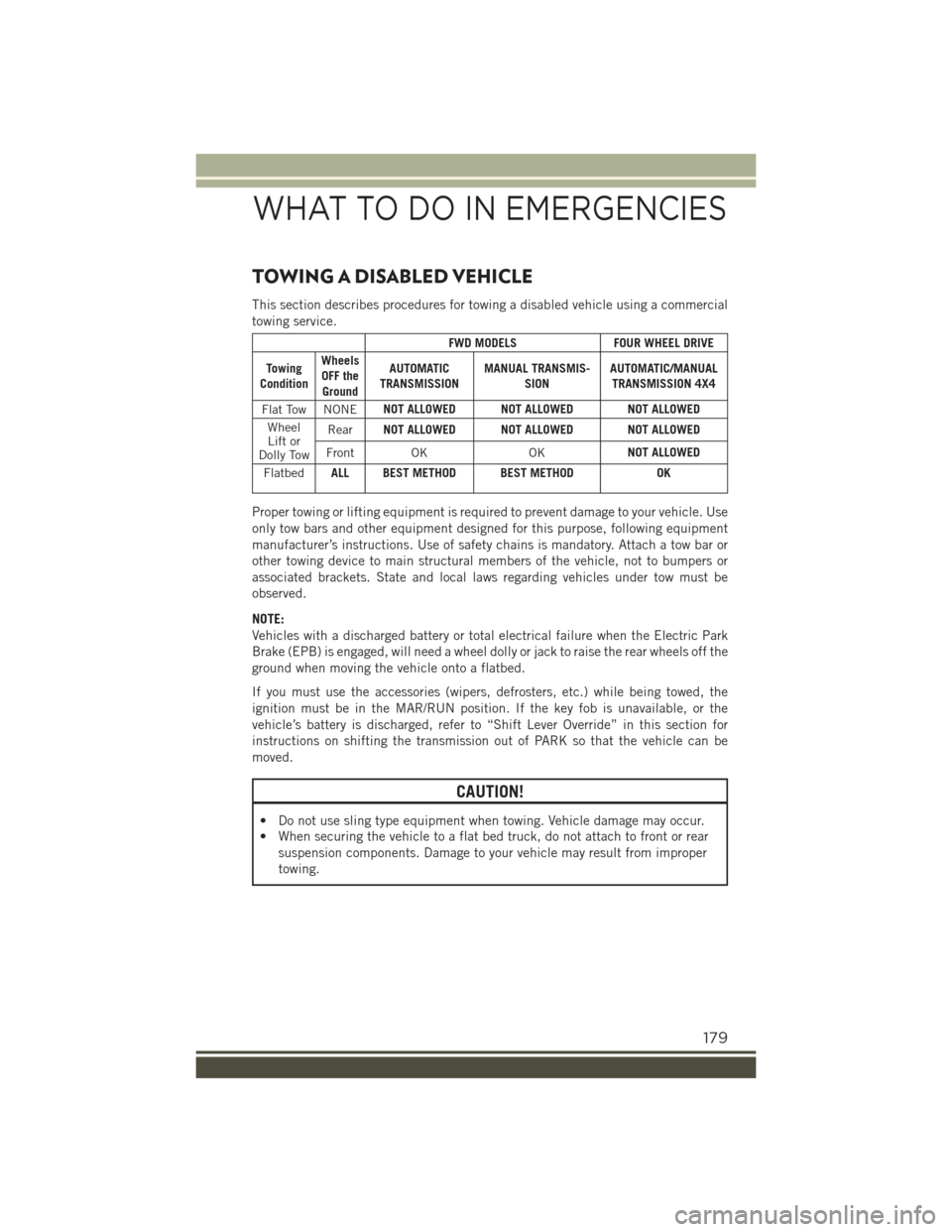
TOWING A DISABLED VEHICLE
This section describes procedures for towing a disabled vehicle using a commercial
towing service.
FWD MODELSFOUR WHEEL DRIVE
TowingCondition
WheelsOFF theGround
AUTOMATICTRANSMISSIONMANUAL TRANSMIS-SIONAUTOMATIC/MANUALTRANSMISSION 4X4
Flat Tow NONENOT ALLOWED NOT ALLOWED NOT ALLOWED
WheelLift orDolly Tow
RearNOT ALLOWED NOT ALLOWED NOT ALLOWED
Front OKOKNOT ALLOWED
FlatbedALL BEST METHOD BEST METHODOK
Proper towing or lifting equipment is required to prevent damage to your vehicle. Use
only tow bars and other equipment designed for this purpose, following equipment
manufacturer’s instructions. Use of safety chains is mandatory. Attach a tow bar or
other towing device to main structural members of the vehicle, not to bumpers or
associated brackets. State and local laws regarding vehicles under tow must be
observed.
NOTE:
Vehicles with a discharged battery or total electrical failure when the Electric Park
Brake (EPB) is engaged, will need a wheel dolly or jack to raise the rear wheels off the
ground when moving the vehicle onto a flatbed.
If you must use the accessories (wipers, defrosters, etc.) while being towed, the
ignition must be in the MAR/RUN position. If the key fob is unavailable, or the
vehicle’s battery is discharged, refer to “Shift Lever Override” in this section for
instructions on shifting the transmission out of PARK so that the vehicle can be
moved.
CAUTION!
• Do not use sling type equipment when towing. Vehicle damage may occur.
• When securing the vehicle to a flat bed truck, do not attach to front or rear
suspension components. Damage to your vehicle may result from improper
towing.
WHAT TO DO IN EMERGENCIES
179
Page 189 of 220
E85 FLEXIBLE FUEL — 2.4L ENGINE ONLY
Refer to your Owner's Manual on the DVD for further details.
CAUTION!
Only vehicles with the E-85 fuel filler door label or a yellow gas cap can operate on
E-85.
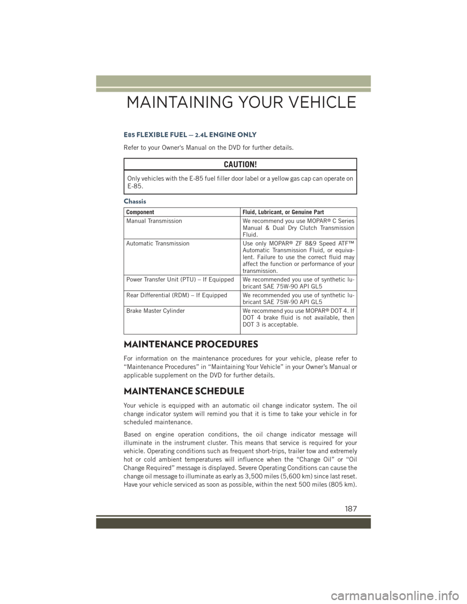
Chassis
ComponentFluid, Lubricant, or Genuine Part
Manual TransmissionWe recommend you use MOPAR®C SeriesManual & Dual Dry Clutch TransmissionFluid.
Automatic TransmissionUse only MOPAR®ZF 8&9 Speed ATF™Automatic Transmission Fluid, or equiva-lent. Failure to use the correct fluid mayaffect the function or performance of yourtransmission.
Power Transfer Unit (PTU) – If Equipped We recommended you use of synthetic lu-bricant SAE 75W-90 API GL5
Rear Differential (RDM) – If Equipped We recommended you use of synthetic lu-bricant SAE 75W-90 API GL5
Brake Master CylinderWe recommend you use MOPAR®DOT 4. IfDOT 4 brake fluid is not available, thenDOT 3 is acceptable.
MAINTENANCE PROCEDURES
For information on the maintenance procedures for your vehicle, please refer to
“Maintenance Procedures” in “Maintaining Your Vehicle” in your Owner’s Manual or
applicable supplement on the DVD for further details.
MAINTENANCE SCHEDULE
Your vehicle is equipped with an automatic oil change indicator system. The oil
change indicator system will remind you that it is time to take your vehicle in for
scheduled maintenance.
Based on engine operation conditions, the oil change indicator message will
illuminate in the instrument cluster. This means that service is required for your
vehicle. Operating conditions such as frequent short-trips, trailer tow and extremely
hot or cold ambient temperatures will influence when the “Change Oil” or “Oil
Change Required” message is displayed. Severe Operating Conditions can cause the
change oil message to illuminate as early as 3,500 miles (5,600 km) since last reset.
Have your vehicle serviced as soon as possible, within the next 500 miles (805 km).
MAINTAINING YOUR VEHICLE
187
Page 197 of 220
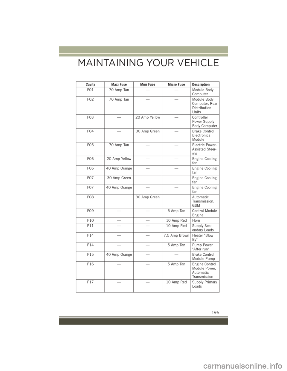
Cavity Maxi Fuse Mini Fuse Micro Fuse Description
F01 70 Amp Tan ——ModuleBodyComputer
F02 70 Amp Tan ——ModuleBodyComputer, RearDistributionUnits
F03— 20 Amp Yellow — ControllerPower SupplyBody Computer
F04— 30 Amp Green — Brake ControlElectronicsModule
F05 70 Amp Tan ——ElectricPower-Assisted Steer-ing
F06 20 Amp Yellow ——EngineCoolingfan
F06 40 Amp Orange ——EngineCoolingfan
F07 30 Amp Green ——EngineCoolingfan
F07 40 Amp Orange ——EngineCoolingfan
F0830 Amp GreenAutomaticTransmission,GSM
F09——5AmpTanControlModuleEngine
F10——10AmpRedHorn
F11——10AmpRedSupplySec-ondary Loads
F14——7.5AmpBrownHeater"BlowBy"
F14——5AmpTanPumpPower"After run"
F15 40 Amp Orange ——BrakeControlModule Pump
F16——5AmpTanEngineControlModule Power,AutomaticTransmission
F17——10AmpRedSupplyPrimaryLoads
MAINTAINING YOUR VEHICLE
195
Page 199 of 220
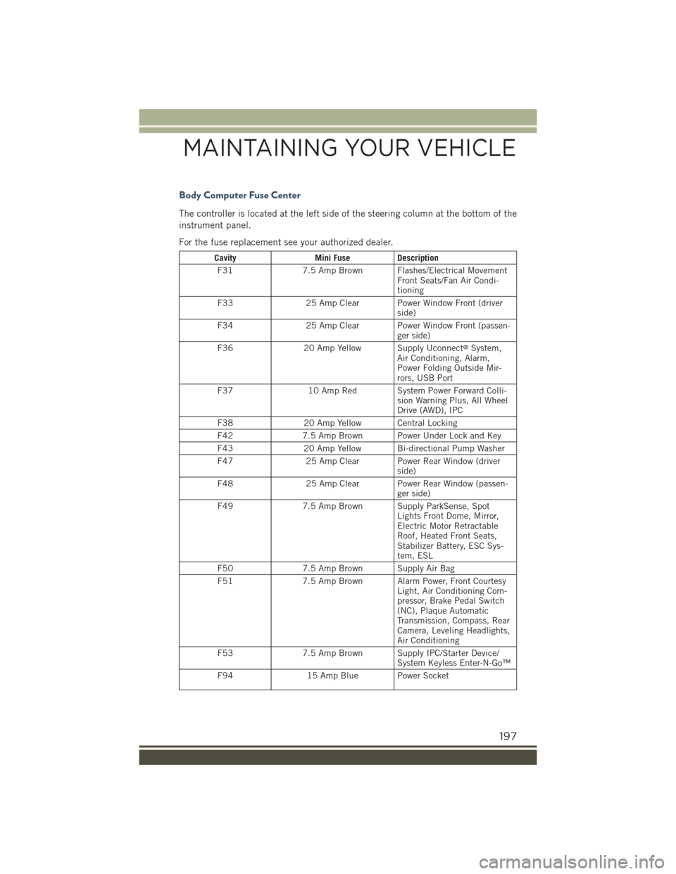
Body Computer Fuse Center
The controller is located at the left side of the steering column at the bottom of the
instrument panel.
For the fuse replacement see your authorized dealer.
CavityMini FuseDescription
F317.5 Amp Brown Flashes/Electrical MovementFront Seats/Fan Air Condi-tioning
F3325 Amp Clear Power Window Front (driverside)
F3425 Amp Clear Power Window Front (passen-ger side)
F3620 Amp Yellow Supply Uconnect®System,Air Conditioning, Alarm,Power Folding Outside Mir-rors, USB Port
F3710 Amp Red System Power Forward Colli-sion Warning Plus, All WheelDrive (AWD), IPC
F3820 Amp Yellow Central Locking
F427.5 Amp Brown Power Under Lock and Key
F4320 Amp Yellow Bi-directional Pump Washer
F4725 Amp Clear Power Rear Window (driverside)
F4825 Amp Clear Power Rear Window (passen-ger side)
F497.5 Amp Brown Supply ParkSense, SpotLights Front Dome, Mirror,Electric Motor RetractableRoof, Heated Front Seats,Stabilizer Battery, ESC Sys-tem, ESL
F507.5 Amp Brown Supply Air Bag
F517.5 Amp Brown Alarm Power, Front CourtesyLight, Air Conditioning Com-pressor, Brake Pedal Switch(NC), Plaque AutomaticTransmission, Compass, RearCamera, Leveling Headlights,Air Conditioning
F537.5 Amp Brown Supply IPC/Starter Device/System Keyless Enter-N-Go™
F9415 Amp Blue Power Socket
MAINTAINING YOUR VEHICLE
197
Page 210 of 220
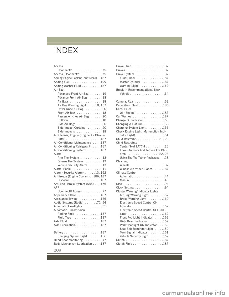
Access
Uconnect®.............75
Access, Uconnect®...........75
Adding Engine Coolant (Antifreeze)..187
Adding Fuel..............199
Adding Washer Fluid.........187
Air Bag
Advanced Front Air Bag . . . . . .19
Advance Front Air Bag . . . . . .18
Air Bags . . . . . . . . . . . . . . .18Air Bag Warning Light . . . .18, 157Driver Knee Air Bag........20Front Air Bag . . . . . . . . . . . .18Passenger Knee Air Bag......20Rollover...............18Side Air Bags . . . . . . . . . . . .20Side Impact Curtains.......20Side Impacts . . . . . . . . . . . .18Air Cleaner, Engine (Engine Air CleanerFilter)................187Air Conditioner Maintenance....187Air Conditioning Refrigerant.....187Air Conditioning System.......187AlarmArm The System..........13Disarm The System........13Vehicle Security Alarm......13Alarm, Panic..............11Alarm (Security Alarm).....13,162Antifreeze (Engine Coolant) . .186, 187Disposal . . . . . . . . . . . . . .187Anti-Lock Brake System (ABS) . . .156APPUconnect®Access . . . . . . . . .77Appearance Care...........187Assistance Towing..........156Audio Systems (Radio)......72,96Automatic Headlights.........35Automatic TransmissionAdding Fluid...........187Fluid Type . . . . . . . . . . . .187Axle Fluid . . . . . . . . . . . . . . .187Axle Lubrication............187
Battery.................187Charging System Light.....156Blind Spot Monitoring.........47Body Mechanism Lubrication....187
Brake Fluid . . . . . . . . . . . . . .187
Brakes . . . . . . . . . . . . . . . . .187
Brake System.............187
Fluid Check . . . . . . . . . . . .187
Master Cylinder.........187
Warning Light..........160
Break-In Recommendations, New
Vehicle................34
Camera, Rear..............62Capacities, Fluid...........186Caps, FillerOil (Engine)............187Car Washes . . . . . . . . . . . . . .187Change Oil Indicator.........163Changing A Flat Tire . . . . . . . . .168Charging System Light........156Check Engine Light (Malfunction Indi-cator Light).............161Child Restraint...........21,22Child RestraintsCenter Seat LATCH . . . . . . . . .23Lower Anchors And Tethers For Chil-dren . . . . . . . . . . . . . .22, 23
Using The Top Tether Anchorage..23CleaningWheels..............187Windshield Wiper Blades....187Climate ControlAutomatic..............44Manual . . . . . . . . . . . . . . .43Clock...................94Clock Setting..............94Cluster Warning/Indicator LightsAir Bag Warning Light . . . . . .157Brake Warning Light.......160Electronic Speed Control ONIndicator..............162Electronic Speed Control SET Indi-cator................162Front Fog Light Indicator....162High Beam Indicator......162Park/Headlight ON Indicator . .162Seat Belt Reminder Light . . . .159Turn Signal Indicator......161Vehicle Security Light......162Clutch . . . . . . . . . . . . . . . . .187Clutch Fluid . . . . . . . . . . . . . .187
INDEX
208