battery JEEP RENEGADE 2015 1.G Owner's Manual
[x] Cancel search | Manufacturer: JEEP, Model Year: 2015, Model line: RENEGADE, Model: JEEP RENEGADE 2015 1.GPages: 220, PDF Size: 34.11 MB
Page 176 of 220
JUMP-STARTING PROCEDURES
If your vehicle has a discharged battery it can be jump-started using a set of jumper
cables and a battery in another vehicle or by using a portable battery booster pack.
Jump-starting can be dangerous if done improperly so please follow the procedures
in this section carefully.
NOTE:
When using a portable battery booster pack follow the manufacturer’s operating
instructions and precautions.
CAUTION!
Do not use a portable battery booster pack or any other booster source with a
system voltage greater than 12 Volts or damage to the battery, starter motor,
alternator or electrical system may occur.
WARNING!
Do not attempt jump-starting if the battery is frozen. It could rupture or explode
and cause personal injury.
Preparations For Jump-Start
The battery in your vehicle is located in the front of the engine compartment, behind
the left headlight assembly.
NOTE:
The positive battery post is covered with a protective cap. Lift up on the cap to gain
access to the positive battery post.
WARNING!
• Take care to avoid the radiator cooling fan whenever the hood is raised. It can
start anytime the ignition switch is ON. You can be injured by moving fan
blades.
• Remove any metal jewelry such as rings, watch bands and bracelets that could
make an inadvertent electrical contact. You could be seriously injured.
• Batteries contain sulfuric acid that can burn your skin or eyes and generate
hydrogen gas which is flammable and explosive. Keep open flames or sparks
away from the battery.
Proceed as follows:
1. Set the Electric Park Brake, shift the automatic transmission into PARK (manual
transmission in NEUTRAL) and turn the ignition to STOP/OFF.
2. Turn off the heater, radio, and all unnecessary electrical accessories.
WHAT TO DO IN EMERGENCIES
174
Page 177 of 220
3. If using another vehicle to jump-start the battery, park the vehicle within the
jumper cables reach, set the parking brake and make sure the ignition is
STOP/OFF.
WARNING!
Do not allow vehicles to touch each other as this could establish a ground
connection and personal injury could result.
Jump-Starting Procedure
WARNING!
Failure to follow this jump-starting procedure could result in personal injury or
property damage due to battery explosion.
CAUTION!
Failure to follow these procedures could result in damage to the charging system
of the booster vehicle or the discharged vehicle.
Connecting The Jumper Cables
1. Connect the positive(+)end of the jumper cable to the positive(+)post of the
discharged vehicle.
2. Connect the opposite end of the positive(+)jumper cable to the positive(+)post
of the booster battery.
3. Connect the negative(-)end of the jumper cable to the negative(-)post of the
booster battery.
4. Connect the opposite end of the negative(-)jumper cable to a good engine ground
(exposed metal part of the discharged vehicle’s engine) away from the battery and
the fuel injection system.
WARNING!
Do not connect the jumper cable to the negative (-) post of the discharged battery.
The resulting electrical spark could cause the battery to explode and could result
in serious injury. Only use the specific ground point, do not use any other exposed
metal parts.
5. Start the engine in the vehicle that has the booster battery, let the engine idle a
few minutes, and then start the engine in the vehicle with the discharged battery.
WHAT TO DO IN EMERGENCIES
175
Page 178 of 220
6. Once the engine is started, remove the jumper cables in the reverse sequence:
Disconnecting The Jumper Cables
1. Disconnect the negative(-)end of the jumper cable from the engine ground of the
vehicle with the discharged battery.
2. Disconnect the opposite end of the negative(-)jumper cable from the negative(-)
post of the booster battery.
3. Disconnect the positive(+)end of the jumper cable from the positive(+)post of
the booster battery.
4. Disconnect the opposite end of the positive(+)jumper cable from the positive(+)
post of the vehicle with the discharged battery.
If frequent jump-starting is required to start your vehicle you should have the battery
and charging system inspected at your authorized dealer.
CAUTION!
Accessories plugged into the vehicle power outlets draw power from the vehicle’s
battery, even when not in use (i.e., cellular phones, etc.). Eventually, if plugged in
long enough without engine operation, the vehicle’s battery will discharge suffi-
ciently to degrade battery life and/or prevent the engine from starting.
FREEING A STUCK VEHICLE
If your vehicle becomes stuck in mud, sand or snow, it can often be moved using a
rocking motion. Turn the steering wheel right and left to clear the area around the
front wheels. For vehicles with automatic transmission, push and hold the lock
button on the shift lever. Then shift back and forth between DRIVE and REVERSE
(with automatic transmission) or 2ND GEAR and REVERSE (with manual transmis-
sion), while gently pushing the accelerator.
For Vehicles With Automatic Transmission:
Shifts between DRIVE and REVERSE can only be achieved at wheel speeds of 5 mph
(8 km/h) or less. Whenever the transmission remains in NEUTRAL for more than two
seconds, you must push the brake pedal to engage DRIVE or REVERSE.
Use the least amount of accelerator pedal pressure that will maintain the rocking
motion without spinning the wheels or racing the engine.
WHAT TO DO IN EMERGENCIES
176
Page 181 of 220
TOWING A DISABLED VEHICLE
This section describes procedures for towing a disabled vehicle using a commercial
towing service.
FWD MODELSFOUR WHEEL DRIVE
TowingCondition
WheelsOFF theGround
AUTOMATICTRANSMISSIONMANUAL TRANSMIS-SIONAUTOMATIC/MANUALTRANSMISSION 4X4
Flat Tow NONENOT ALLOWED NOT ALLOWED NOT ALLOWED
WheelLift orDolly Tow
RearNOT ALLOWED NOT ALLOWED NOT ALLOWED
Front OKOKNOT ALLOWED
FlatbedALL BEST METHOD BEST METHODOK
Proper towing or lifting equipment is required to prevent damage to your vehicle. Use
only tow bars and other equipment designed for this purpose, following equipment
manufacturer’s instructions. Use of safety chains is mandatory. Attach a tow bar or
other towing device to main structural members of the vehicle, not to bumpers or
associated brackets. State and local laws regarding vehicles under tow must be
observed.
NOTE:
Vehicles with a discharged battery or total electrical failure when the Electric Park
Brake (EPB) is engaged, will need a wheel dolly or jack to raise the rear wheels off the
ground when moving the vehicle onto a flatbed.
If you must use the accessories (wipers, defrosters, etc.) while being towed, the
ignition must be in the MAR/RUN position. If the key fob is unavailable, or the
vehicle’s battery is discharged, refer to “Shift Lever Override” in this section for
instructions on shifting the transmission out of PARK so that the vehicle can be
moved.
CAUTION!
• Do not use sling type equipment when towing. Vehicle damage may occur.
• When securing the vehicle to a flat bed truck, do not attach to front or rear
suspension components. Damage to your vehicle may result from improper
towing.
WHAT TO DO IN EMERGENCIES
179
Page 185 of 220
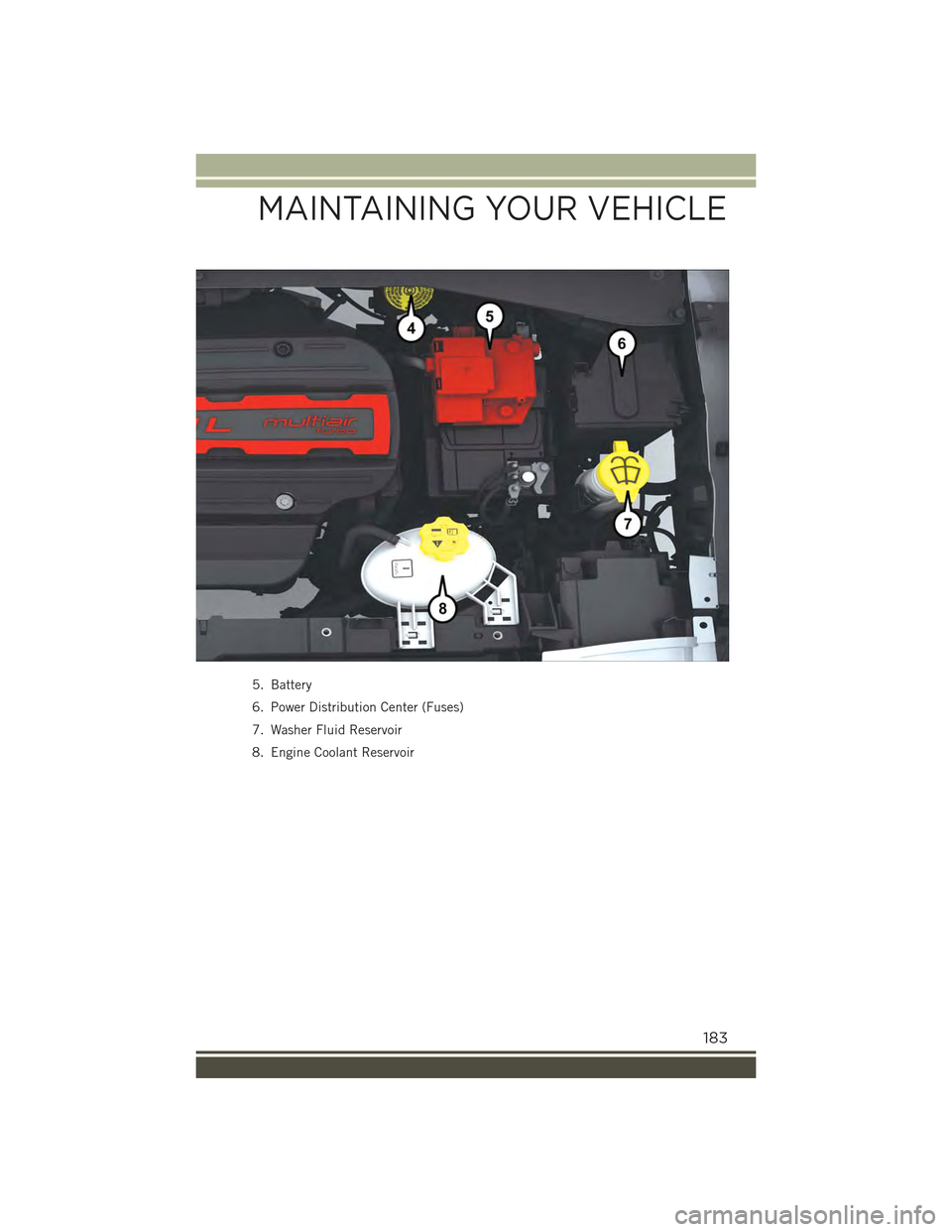
5. Battery
6. Power Distribution Center (Fuses)
7. Washer Fluid Reservoir
8. Engine Coolant Reservoir
MAINTAINING YOUR VEHICLE
183
Page 187 of 220
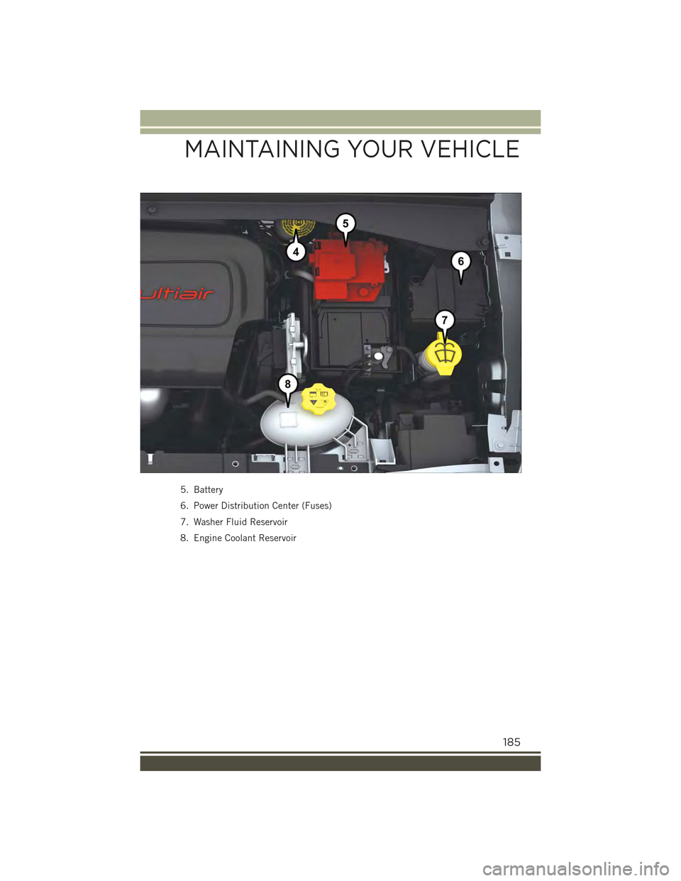
5. Battery
6. Power Distribution Center (Fuses)
7. Washer Fluid Reservoir
8. Engine Coolant Reservoir
MAINTAINING YOUR VEHICLE
185
Page 190 of 220
Your authorized dealer will reset the oil change indicator message after completing
the scheduled oil change. If a scheduled oil change is performed by someone other
than your authorized dealer, the message can be reset by referring to the steps
described under “Electronic Vehicle Information Center (EVIC)/Driver Information
Display (DID)” in “Getting To Know Your Instrument Panel” in your Owners Manual
on the DVD for further information.
NOTE:
Under no circumstances should oil change intervals exceed 10,000 miles
(16,000 km) or one year, whichever comes first.
Severe Duty All Models
Change Engine Oil at 4000 miles (6,500 km) if the vehicle is operated in a dusty and
off road environment. This type of vehicle use is considered Severe Duty
NOTE:
The Oil Change Indicator will not illuminate under these conditions.
Once A Month Or Before A Long Trip:
• Check engine oil level.
• Check windshield washer fluid level.
• Check the tire inflation pressures and look for unusual wear or damage.
• Check the fluid levels of the coolant reservoir, and brake master cylinder reservoir,
and fill as needed.
• Check function of all interior and exterior lights.
Required Maintenance Intervals.
At Every Oil Change Interval As Indicated By Oil Change Indicator System:
Change oil and filter.
Inspect battery and clean and tighten terminals as required.
Inspect brake pads, shoes, rotors, drums, and hoses.
Inspect engine cooling system protection and hoses.
Check and adjust hand brake.
Inspect exhaust system.
Inspect engine air filter if using in dusty or off-road conditions.
Refer to the “Maintenance Chart” on the following page for the required maintenance
intervals.
MAINTAINING YOUR VEHICLE
188
Page 191 of 220
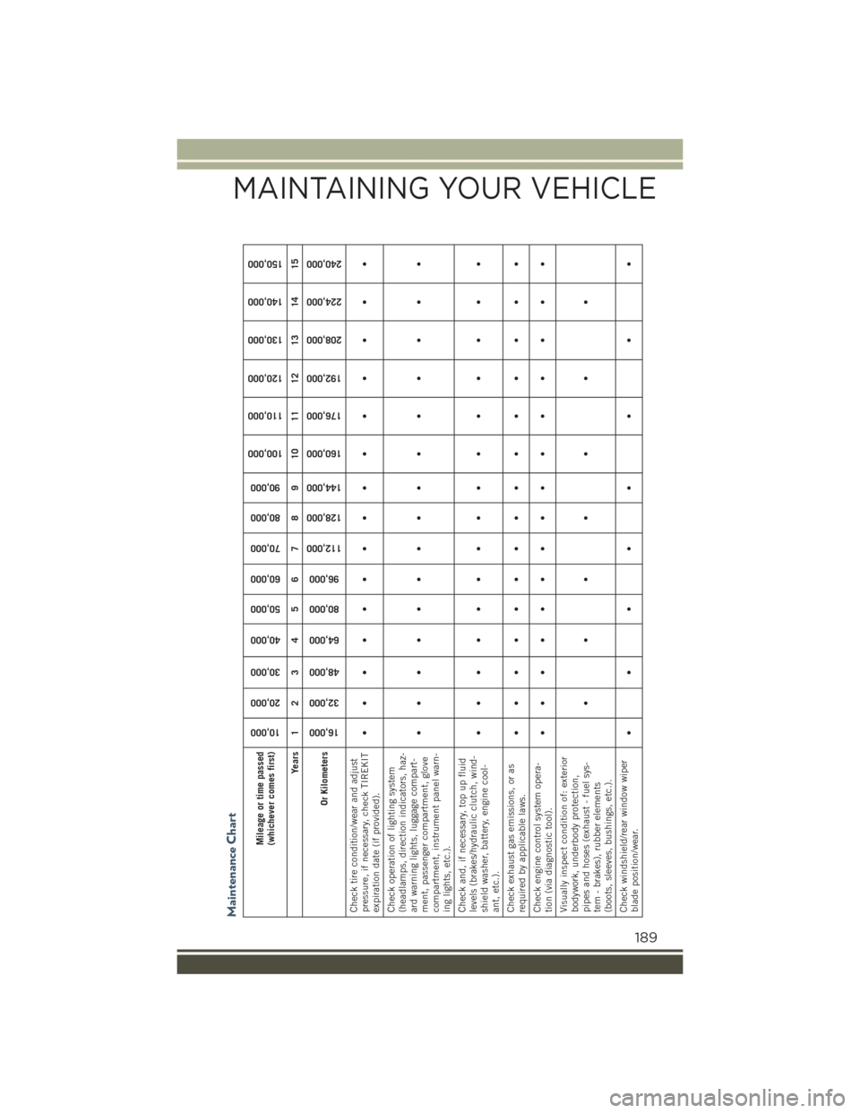
Maintenance Chart
Mileage or time passed(whichever comes first)
10,000
20,000
30,000
40,000
50,000
60,000
70,000
80,000
90,000
100,000
110,000
120,000
130,000
140,000
150,000
Years 1 2 3 4 5 6 7 8 9 10 11 12 13 14 15
Or Kilometers
16,000
32,000
48,000
64,000
80,000
96,000
112,000
128,000
144,000
160,000
176,000
192,000
208,000
224,000
240,000
Check tire condition/wear and adjustpressure, if necessary, check TIREKITexpiration date (if provided).
•• • • •• • •• • • • • • •
Check operation of lighting system(headlamps, direction indicators, haz-ard warning lights, luggage compart-ment, passenger compartment, glovecompartment, instrument panel warn-ing lights, etc.).
•• • • •• • •• • • • • • •
Check and, if necessary, top up fluidlevels (brakes/hydraulic clutch, wind-shield washer, battery, engine cool-ant, etc.).
•• • • •• • •• • • • • • •
Check exhaust gas emissions, or asrequired by applicable laws.
•• • • •• • •• • • • • • •
Check engine control system opera-tion (via diagnostic tool).
•• • • •• • •• • • • • • •
Visually inspect condition of: exteriorbodywork, underbody protection,pipes and hoses (exhaust - fuel sys-tem - brakes), rubber elements(boots, sleeves, bushings, etc.).
•••• • • •
Check windshield/rear window wiperblade position/wear.
•• ••• • • •
MAINTAINING YOUR VEHICLE
189
Page 198 of 220
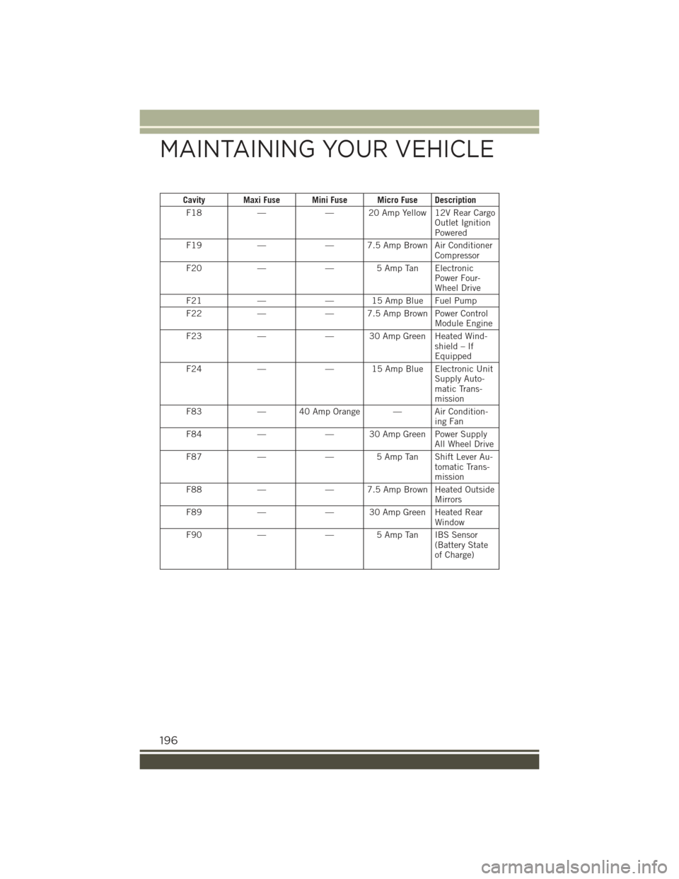
Cavity Maxi Fuse Mini Fuse Micro Fuse Description
F18——20AmpYellow12VRearCargoOutlet IgnitionPowered
F19——7.5AmpBrownAirConditionerCompressor
F20—— 5 Amp Tan ElectronicPower Four-Wheel Drive
F21——15AmpBlueFuelPump
F22——7.5AmpBrownPowerControlModule Engine
F23——30AmpGreenHeatedWind-shield – IfEquipped
F24——15AmpBlueElectronicUnitSupply Auto-matic Trans-mission
F83—40AmpOrange—AirCondition-ing Fan
F84——30AmpGreenPowerSupplyAll Wheel Drive
F87——5AmpTanShiftLeverAu-tomatic Trans-mission
F88——7.5AmpBrownHeatedOutsideMirrors
F89——30AmpGreenHeatedRearWindow
F90——5AmpTanIBSSensor(Battery Stateof Charge)
MAINTAINING YOUR VEHICLE
196
Page 199 of 220
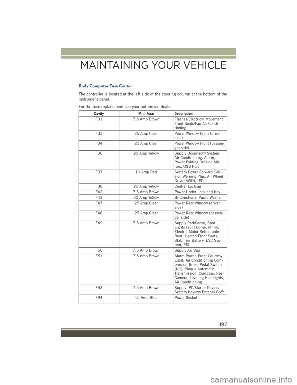
Body Computer Fuse Center
The controller is located at the left side of the steering column at the bottom of the
instrument panel.
For the fuse replacement see your authorized dealer.
CavityMini FuseDescription
F317.5 Amp Brown Flashes/Electrical MovementFront Seats/Fan Air Condi-tioning
F3325 Amp Clear Power Window Front (driverside)
F3425 Amp Clear Power Window Front (passen-ger side)
F3620 Amp Yellow Supply Uconnect®System,Air Conditioning, Alarm,Power Folding Outside Mir-rors, USB Port
F3710 Amp Red System Power Forward Colli-sion Warning Plus, All WheelDrive (AWD), IPC
F3820 Amp Yellow Central Locking
F427.5 Amp Brown Power Under Lock and Key
F4320 Amp Yellow Bi-directional Pump Washer
F4725 Amp Clear Power Rear Window (driverside)
F4825 Amp Clear Power Rear Window (passen-ger side)
F497.5 Amp Brown Supply ParkSense, SpotLights Front Dome, Mirror,Electric Motor RetractableRoof, Heated Front Seats,Stabilizer Battery, ESC Sys-tem, ESL
F507.5 Amp Brown Supply Air Bag
F517.5 Amp Brown Alarm Power, Front CourtesyLight, Air Conditioning Com-pressor, Brake Pedal Switch(NC), Plaque AutomaticTransmission, Compass, RearCamera, Leveling Headlights,Air Conditioning
F537.5 Amp Brown Supply IPC/Starter Device/System Keyless Enter-N-Go™
F9415 Amp Blue Power Socket
MAINTAINING YOUR VEHICLE
197