engine JEEP RENEGADE 2015 1.G User Guide
[x] Cancel search | Manufacturer: JEEP, Model Year: 2015, Model line: RENEGADE, Model: JEEP RENEGADE 2015 1.GPages: 220, PDF Size: 34.11 MB
Page 3 of 220
INTRODUCTION/WELCOME
WELCOME FROM FCA US LLC...... 2
CONTROLS AT A GLANCE
DRIVER COCKPIT.............. 6INSTRUMENT CLUSTER.......... 8
GETTING STARTED
KEY FOB . . . . . . . . . . . . . . . . . . . 10REMOTE START............... 12VEHICLE SECURITY ALARM....... 13KEYLESS ENTER-N-GO™......... 14SEAT BELT SYSTEMS........... 17SUPPLEMENTAL RESTRAINT SYSTEM(SRS) — AIR BAGS............ 18CHILD RESTRAINTS............ 21HEAD RESTRAINTS............. 25SEATS . . . . . . . . . . . . . . . . . . . . . 27REAR SEATS................ 30HEATED STEERING WHEEL........ 32TILT/TELESCOPING STEERINGCOLUMN................... 33
OPERATING YOUR VEHICLE
ENGINE BREAK-INRECOMMENDATIONS........... 34EXTERIOR LIGHTS............. 34WINDSHIELD WIPER/WASHER...... 37ELECTRONIC SPEED CONTROL..... 40MANUAL CLIMATE CONTROLS...... 43AUTOMATIC TEMPERATURE CONTROLS(ATC) . . . . . . . . . . . . . . . . . . . . . . 44ELECTRIC PARK BRAKE (EPB)...... 45BLIND SPOT MONITORING (BSM).... 47FORWARD COLLISION WARNING (FCW)WITH MITIGATION . . . . . . . . . . . . . 51LANESENSE................. 55PA R K S E N S E®REAR PARK ASSIST . . . 58PARKVIEW®REAR BACK UP CAMERA.. 62RETRACTABLE ROOF (MY SKY)..... 63
ELECTRONICS
YOUR VEHICLE'S SOUND SYSTEM . . . 72IDENTIFYING YOUR RADIO........ 74Uconnect®ACCESS............. 75Uconnect®3.0 . . . . . . . . . . . . . . . . 91Uconnect®5.0 . . . . . . . . . . . . . . . . 94Uconnect®6.5AN . . . . . . . . . . . . . 106Uconnect®PHONE............ 128STEERING WHEEL AUDIO CONTROLS.. 138ELECTRONIC VEHICLE INFORMATIONCENTER (EVIC) AND DRIVER INFORMATIONDISPLAY (DID)............... 138PROGRAMMABLE FEATURES...... 146POWER INVERTER — IF EQUIPPED . . 146POWER OUTLET.............. 147
OFF-ROAD CAPABILITIES
FOUR WHEEL DRIVE — JEEP ACTIVEDRIVE (4WD) AND JEEP ACTIVE DRIVE LOW(4WD LOW)................. 150
SELEC-TERRAIN™............ 152
UTILITY
CARGO AREA FEATURES........ 153TRAILER TOWING............ 153RECREATIONAL TOWING........ 154
WHAT TO DO IN EMERGENCIES
ROADSIDE ASSISTANCE......... 156INSTRUMENT CLUSTER WARNINGLIGHTS................... 156INSTRUMENT CLUSTER INDICATORLIGHTS................... 161IF YOUR ENGINE OVERHEATS..... 164TIRE SERVICE KIT STORAGE...... 165JACKING AND TIRE CHANGING.... 168JUMP-STARTING PROCEDURES.... 174FREEING A STUCK VEHICLE...... 176EMERGENCY TOW HOOKS....... 177SHIFT LEVER OVERRIDE........ 178TOWING A DISABLED VEHICLE.... 179
MAINTAINING YOUR VEHICLE
TO OPEN AND CLOSE THE HOOD . . . 181ENGINE COMPARTMENT — 1.4LTURBO................... 182ENGINE COMPARTMENT — 2.4L . . . 184FLUID CAPACITIES............ 186FLUIDS, LUBRICANTS AND GENUINEPA RT S . . . . . . . . . . . . . . . . . . . . 1 8 6MAINTENANCE PROCEDURES..... 187MAINTENANCE SCHEDULE....... 187FUSES.................... 194ADDING FUEL............... 199TIRE PRESSURES............. 200SPARE TIRES — IF EQUIPPED..... 201WHEEL AND WHEEL TRIM CARE . . . 202BULB REPLACEMENT.......... 203
CUSTOMER ASSISTANCE
FCA US LLC CUSTOMER CENTER . . . 204CHRYSLER CANADA INC. CUSTOMERCENTER.................. 204ASSISTANCE FOR THE HEARINGIMPAIRED . . . . . . . . . . . . . . . . . 204PUBLICATIONS ORDERING....... 204REPORTING SAFETY DEFECTS IN THEUNITED STATES . . . . . . . . . . . . . . 205
MOPAR® ACCESSORIES
AUTHENTIC ACCESSORIES BYMOPAR®.................. 206
FAQ ’ s
FREQUENTLY ASKED QUESTIONS . . 207
INDEX.................. 208
TABLE OF CONTENTS
Page 13 of 220
NOTE:
In case the ignition switch does not change with the push of a button, the RKE
transmitter (Key Fob) may have a low or dead battery. In this situation, a back up
method can be used to operate the ignition switch. Put the nose side (side opposite
of the emergency key) of the Key Fob against the ENGINE START/STOP button and
push to operate the ignition switch.
• The Ignition Node Module (IGNM) op-
erates similar to an ignition switch. It
has three operating positions, two with
detents and one that is spring-loaded.
The detent positions are STOP/OFF
and MAR/RUN. The AVV/START posi-
tion is a spring-loaded momentary con-
tact position. When released from the
AVV/START position, the switch auto-
matically returns to the MAR/RUN
position.
Locking And Unlocking The
Doors/Liftgate
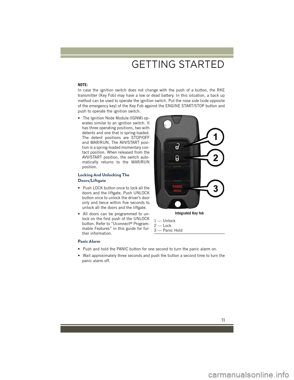
• Push LOCK button once to lock all the
doors and the liftgate. Push UNLOCK
button once to unlock the driver’s door
only and twice within five seconds to
unlock all the doors and the liftgate.
• All doors can be programmed to un-
lock on the first push of the UNLOCK
button. Refer to “Uconnect®Program-
mable Features” in this guide for fur-
ther information.
Panic Alarm
• Push and hold the PANIC button for one second to turn the panic alarm on.
• Wait approximately three seconds and push the button a second time to turn the
panic alarm off.
Integrated Key fob
1 — Unlock2 — Lock3 — Panic Hold
GETTING STARTED
11
Page 14 of 220
WARNING!
• When leaving the vehicle, always make sure the keyless ignition node is in
“OFF” mode, remove the Key Fob from the vehicle and lock the vehicle.
• Never leave children alone in a vehicle, or with access to an unlocked vehicle.
Allowing children to be in a vehicle unattended is dangerous for a number of
reasons. A child or others could be seriously or fatally injured. Children should
be warned not to touch the parking brake, brake pedal or the transmission gear
selector.
• Do not leave the Key Fob in or near the vehicle (or in a location accessible to
children), and do not leave the ignition of a vehicle equipped with Keyless
Enter-N-Go™ in the ON/RUN mode. A child could operate power windows,
other controls, or move the vehicle.
REMOTE START
This system uses the Remote Keyless Entry (RKE) transmitter to start the engine
conveniently from outside the vehicle while still maintaining security. The system has
a range of at least 300 ft (91 m).
The Remote Starting System also activates the Climate Control and (if equipped) the
optional heated seats and optional heated steering wheel depending on temperatures
outside and inside the car.
• Push REMOTE START buttonx2on the Key Fob twice within five seconds.
Pushing the REMOTE START button a third time shuts the engine off.
• To drive the vehicle, push UNLOCK button, insert the key in the ignition and turn
to the MAR/RUN position.
• With Remote Start, the engine will only run for 15 minutes (timeout) unless the
ignition key is placed in the MAR/RUN position.
• The vehicle must be started with the key after two consecutive timeouts.
NOTE:
The Remote Start Comfort System can be activated and deactivated through the
Uconnect®Settings. Refer to “Uconnect®Programmable Features” in “Electronics”
for more information on Remote Start Comfort System operation.
WARNING!
• Do not start or run an engine in a closed garage or confined area. Exhaust gas
contains Carbon Monoxide (CO) which is odorless and colorless. Carbon
Monoxide is poisonous and can cause serious injury or death when inhaled.
• Keep Key Fob transmitters away from children. Operation of the Remote Start
System, windows, door locks or other controls could cause serious injury or
death.
GETTING STARTED
12
Page 18 of 220
Lock Or Unlock The Liftgate
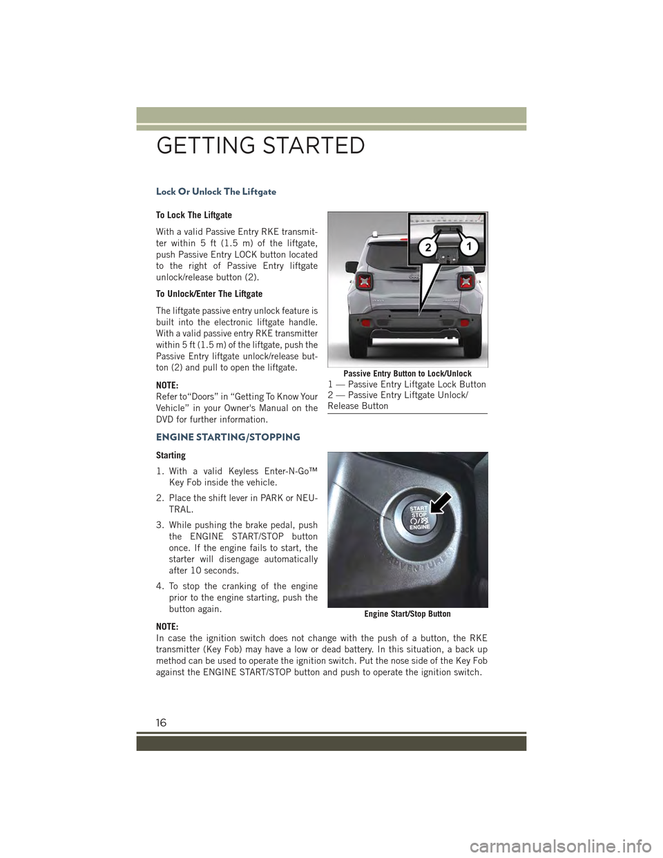
To Lock The Liftgate
With a valid Passive Entry RKE transmit-
ter within 5 ft (1.5 m) of the liftgate,
push Passive Entry LOCK button located
to the right of Passive Entry liftgate
unlock/release button (2).
To Unlock/Enter The Liftgate
The liftgate passive entry unlock feature is
built into the electronic liftgate handle.
With a valid passive entry RKE transmitter
within 5 ft (1.5 m) of the liftgate, push the
Passive Entry liftgate unlock/release but-
ton (2) and pull to open the liftgate.
NOTE:
Refer to“Doors” in “Getting To Know Your
Vehicle” in your Owner's Manual on the
DVD for further information.
ENGINE STARTING/STOPPING
Starting
1. With a valid Keyless Enter-N-Go™
Key Fob inside the vehicle.
2. Place the shift lever in PARK or NEU-
TRAL.
3. While pushing the brake pedal, push
the ENGINE START/STOP button
once. If the engine fails to start, the
starter will disengage automatically
after 10 seconds.
4. To stop the cranking of the engine
prior to the engine starting, push the
button again.
NOTE:
In case the ignition switch does not change with the push of a button, the RKE
transmitter (Key Fob) may have a low or dead battery. In this situation, a back up
method can be used to operate the ignition switch. Put the nose side of the Key Fob
against the ENGINE START/STOP button and push to operate the ignition switch.
Passive Entry Button to Lock/Unlock1 — Passive Entry Liftgate Lock Button2 — Passive Entry Liftgate Unlock/Release Button
Engine Start/Stop Button
GETTING STARTED
16
Page 19 of 220
Stopping
1. Place the shift lever in PARK.
2. Push the ENGINE START/STOP button once. The ignition switch will return to the
OFF position.
NOTE:
If the shift lever is not in PARK, the ENGINE START/STOP button must be held for two
seconds and vehicle speed must be above 5 MPH (8 km/h) before the engine will shut
off.
RUN Position With Engine Off
NOTE:
The following functions are with the driver’s foot OFF the Brake Pedal (Transmission
in PARK or NEUTRAL Position).
Starting With The Ignition Switch In The OFF Position:
1. Push the ENGINE START/STOP button once to change the ignition switch to the
RUN position.
2. Push the ENGINE START/STOP button a second time to return the ignition switch
to the OFF position.
NOTE:
If the ignition switch is left in the RUN (engine not running) position and the
transmission is in PARK, the system will automatically time out after 30 minutes of
inactivity and the ignition will switch to the OFF position.
In case the ignition switch does not change with the push of a button, the RKE
transmitter (Key Fob) may have a low or dead battery. In this situation, a back up
method can be used to operate the ignition switch. Put the nose side (side opposite
of the emergency key) of the Key Fob against the ENGINE START/STOP button and
push to operate the ignition switch.
SEAT BELT SYSTEMS
Lap/Shoulder Belts
• All seating positions in your vehicle are equipped with lap/shoulder belts.
• Be sure everyone in your vehicle is in a seat and using a seat belt properly.
• Position the lap belt so that it is snug and lies low across your hips, below your
abdomen. To remove slack in the lap belt portion, pull up on the shoulder belt. To
loosen the lap belt if it is too tight, tilt the latch plate and pull on the lap belt. A
snug seat belt reduces the risk of sliding under the seat belt in a collision.
• Position the shoulder belt across the shoulder and chest with minimal, if any slack
so that it is comfortable and not resting on your neck. The retractor will withdraw
any slack in the shoulder belt.
GETTING STARTED
17
Page 21 of 220
Advanced Front Air Bags
• This vehicle has Advanced Front Air Bags for both the driver and front passenger
as a supplement to the seat belt restraint systems. The Advanced Front Air Bags
will not deploy in every type of collision.
• Advanced Front Air Bags are designed to provide additional protection by
supplementing the seat belts. Advanced Front Air Bags are not expected to reduce
the risk of injury in rear, side, or rollover collisions.
• The Advanced Front Air Bags will not deploy in all frontal collisions, including
some that may produce substantial vehicle damage — for example, some pole
collisions, truck underrides, and angle offset collisions.
• On the other hand, depending on the type and location of impact, Advanced Front
Air Bags may deploy in crashes with little vehicle front-end damage but that
produce a severe initial deceleration.
• Because air bag sensors measure vehicle deceleration over time, vehicle speed
and damage by themselves are not good indicators of whether or not an air bag
should have deployed.
• Seat belts are necessary for your protection in all collisions, and also are needed
to help keep you in position, away from an inflating air bag.
• The air bags must be ready to inflate for your protection in a collision. The
Occupant Restraint Controller (ORC) monitors the internal circuits and intercon-
necting wiring associated with air bag system electrical components.
• The ORC turns on the Air Bag Warning Light in the instrument panel for
approximately four to eight seconds for a self-check when the ignition switch is
first turned to the ON/RUN position. After the self-check, the Air Bag Warning
Light will turn off. If the ORC detects a malfunction in any part of the system, it
turns on the Air Bag Warning Light, either momentarily or continuously. A single
chime will sound to alert you if the light comes on again after initial startup.
• The ORC monitors the readiness of the electronic parts of the air bag system
whenever the ignition switch is in the START or ON/RUN position. If the ignition
switch is in the OFF position or in the ACC position, the air bag system is not on
and the air bags will not inflate.
• If the Air Bag Warning Light in the instrument panel is not on during the four to
eight seconds when the ignition switch is first turned to the ON/RUN position,
stays on, or turns on while driving, have the vehicle serviced by an authorized
service center immediately.
NOTE:
If the speedometer, tachometer, or any engine related gauges are not working, the
Occupant Restraint Controller (ORC) may also be disabled. In this condition the air
bags may not be ready to inflate for your protection. Have an authorized dealer
service the air bag system immediately.
• After any collision, the vehicle should be taken to an authorized dealer immedi-
ately.
GETTING STARTED
19
Page 31 of 220
Power Lumbar Adjustment
Push the switch forward or rearward to increase or decrease the lumbar support. Push
the switch upward or downward to raise or lower the lumbar support.
Heated Seats — If Equipped
The heated seat switches are located on the instrument panel.
You can choose between two heating levels:
• Push the heated seat buttononce to turn the HI setting ON.
• Push the heated seat buttona second time to turn the LO setting ON.
• Push the heated seat buttona third time to turn the heating elements OFF.
If the HI-level setting is selected, the system will automatically switch to LO-level
after approximately 145 minutes of continuous operation. At that time, the display
will change from HI to LO, indicating the change. The LO-level setting will turn OFF
automatically after approximately 60 minutes.
NOTE:
The engine must be running for the heated seats to operate.
Vehicles Equipped With Remote Start
Vehicles equipped with Remote Start, the heated seats can be programed to come on
during a Remote Start.
This feature can be programmed through the Uconnect®system. Refer to
“Uconnect®Settings” in “Multimedia” in your Owner’s Manual on the DVD for
further information.
WARNING!
• Persons who are unable to feel pain to the skin because of advanced age,
chronic illness, diabetes, spinal cord injury, medication, alcohol use, exhaus-
tion or other physical condition must exercise care when using the seat heater.
It may cause burns even at low temperatures, especially if used for long periods
of time.
• Do not place anything on the seat or seatback that insulates against heat, such
as a blanket or cushion. This may cause the seat heater to overheat. Sitting in
a seat that has been overheated could cause serious burns due to the increased
surface temperature of the seat.
GETTING STARTED
29
Page 36 of 220
ENGINE BREAK-IN RECOMMENDATIONS
A long break-in period is not required for the engine and drivetrain (transmission and
axle) in your vehicle.
Drive moderately during the first 300 miles (500 km). After the initial 60 miles
(100 km), speeds up to 50 or 55 mph (80 or 90 km/h) are desirable.
While cruising, brief full-throttle acceleration within the limits of local traffic laws
contributes to a good break-in. Wide-open throttle acceleration in low gear can be
detrimental and should be avoided.
The engine oil installed in the engine at the factory is a high-quality energy
conserving type lubricant. Oil changes should be consistent with anticipated climate
conditions under which vehicle operations will occur. Refer to “Maintaining Your
Vehicle” for the recommended viscosity and quality grades.
NOTE:
A new engine may consume some oil during its first few thousand miles (kilometers)
of operation. This should be considered a normal part of the break-in and not
interpreted as an indication of an engine problem or malfunction.
CAUTION!
Never use Non-Detergent Oil or Straight Mineral Oil in the engine or damage may
result.
EXTERIOR LIGHTS
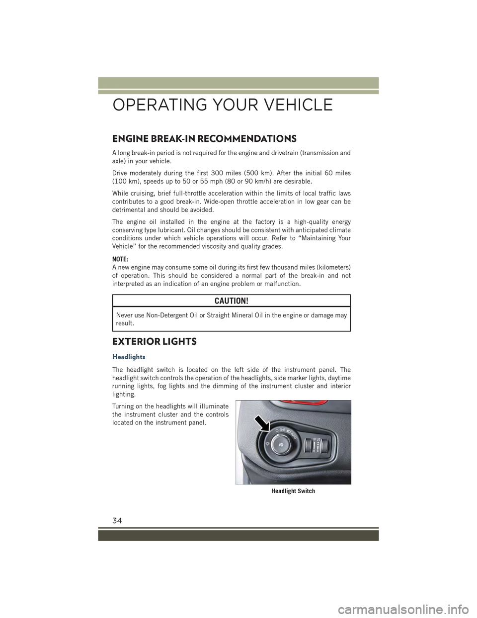
Headlights
The headlight switch is located on the left side of the instrument panel. The
headlight switch controls the operation of the headlights, side marker lights, daytime
running lights, fog lights and the dimming of the instrument cluster and interior
lighting.
Turning on the headlights will illuminate
the instrument cluster and the controls
located on the instrument panel.
Headlight Switch
OPERATING YOUR VEHICLE
34
Page 37 of 220
Automatic Lighting — If Equipped
Light Sensor
The light sensor is equipped with an infrared LED, located on the windshield. It
detects changes in light intensity outside the vehicle, based on the sensitivity of light
set by using the Menu on the display or on the Uconnect®system.
The higher the sensitivity, the lesser the amount of external light required for
controlling the lighting.
Automatic Headlights
Turn the headlight switch to the AUTO position.
When the automatic headlights are enabled, the headlight time delay is active. After
the ignition switch is placed in the STOP/OFF position, the headlights will automati-
cally turn off after approximately 90 seconds depending on the settings of the
feature.
The timing of the headlights is adjustable between 0, 30, 60 and 90 seconds.
NOTE:
The engine must be running before the headlights will come on in the automatic
mode.
Daytime Running Lights (DRL) — If Equipped
The Daytime Running Lights (DRLs) will turn on when the engine is started and
remain on unless the headlights are turned on, the electronic parking brake is
applied, or the engine is shut off.
The DRLs will be disabled during turn signal operation and resume operation when
the turn signal operation has ended.
Front Fog Lights — If Equipped
The front fog light switch is built into the headlight switch.
To activate the front fog lights, turn on the parking lights or the low beam headlights
and push the headlight switch. To turn off the front fog lights, push the headlight
switch a second time or turn off the headlight switch.
An indicator light in the instrument cluster illuminates when the fog lights are turned
on.
NOTE:
The fog lights will operate with the low beam headlights or parking lights on.
Selecting the high beam headlights will turn off the fog lights.
Parking Lights
Rotate the headlight switch to the first position to turn on the parking lights. The
parking light indicator in the cluster will illuminate.
OPERATING YOUR VEHICLE
35
Page 48 of 220
To apply the park brake manually, pull up on the switch momentarily. The BRAKE
warning lamp in the instrument cluster and an indicator on the switch will illuminate.
To release the park brake manually, the ignition switch must be in RUN. Then put
your foot on the brake pedal and push the park brake switch down momentarily. Once
the park brake is fully disengaged, the BRAKE warning lamp and the switch indicator
will extinguish.
The park brake can also be automatically released. With the engine running and the
transmission in gear, release the brake pedal and depress the throttle pedal. For
safety reasons, your seat belt must also be fastened.
NOTE:
• You may hear a slight whirring sound from the back of the vehicle while the parking
brake engages or disengages.
• If your foot is on the brake pedal while you are engaging or disengaging the parking
brake, you may notice a small amount of brake pedal movement.
• The new Auto Park Brake feature can be used to apply the park brake automati-
cally every time you park the vehicle. Auto Park Brake can be enabled and disabled
in the Settings menu in Uconnect®or in “Safe Hold” conditions.
• The parking brake can be engaged even when the ignition switch is OFF, however,
it can only be disengaged when the ignition switch is in the ON/RUN position.
• Safehold is a new feature that will automatically apply the park brake under
certain conditions. The EPB monitors the status of the driver’s seat belt, driver’s
door and pedal positions to determine if the driver may have exited while the
vehicle is still capable of moving and will then automatically apply the park brake
to prevent the vehicle from rolling.
• The EPB fault lamp will illuminate if the EPB switch is held for longer than 20
seconds in either the released or applied position. The light will extinguish upon
releasing the switch.
• Refer to the Starting and Operating section of your vehicle’s Owner’s Manual on
the DVD for further details.
CAUTION!
If the Brake System Warning Light remains on with the parking brake released, a
brake system malfunction is indicated. Have the brake system serviced by an
authorized dealer immediately.
OPERATING YOUR VEHICLE
46