lock JEEP RENEGADE 2015 1.G Service Manual
[x] Cancel search | Manufacturer: JEEP, Model Year: 2015, Model line: RENEGADE, Model: JEEP RENEGADE 2015 1.GPages: 220, PDF Size: 34.11 MB
Page 152 of 220
FOUR WHEEL DRIVE — JEEP ACTIVE DRIVE (4WD)
AND JEEP ACTIVE DRIVE LOW (4WD LOW)
Your vehicle may be equipped with a Power Transfer Unit (PTU). This system is
automatic with no driver inputs or additional driving skills required. Under normal
driving conditions, the front wheels provide most of the traction. If the front wheels
begin to lose traction, power is shifted automatically to the rear wheels. The greater
the front wheel traction loss, the greater the power transfer to the rear wheels.
Additionally, on dry pavement under heavy throttle input (where one may have no
wheel spin), torque will be sent to the rear in a preemptive effort to improve vehicle
launch and performance characteristics.
CAUTION!
All wheels must have the same size and type tires. Unequal tire sizes must not beused. Unequal tire size may cause failure of the power transfer unit.
Four Wheel Drive (4X4)
The four wheel drive (4WD) is fully automatic in normal driving mode.
NOTE:
It is not possible to carry out the change of mode when the car exceeds the speed of
75 mph (120 km/h).
Enabling Four Wheel Drive (4x4)
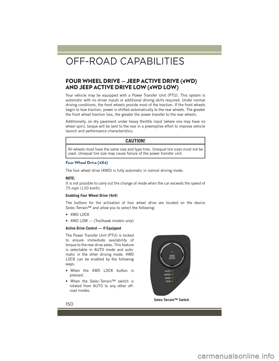
The buttons for the activation of four wheel drive are located on the device
Selec-Terrain™ and allow you to select the following:
• 4WD LOCK
• 4WD LOW — (Trailhawk models only)
Active Drive Control — If Equipped
The Power Transfer Unit (PTU) is locked
to ensure immediate availability of
torque to the rear drive axles. This feature
is selectable in AUTO mode and auto-
matic in the other driving mode. 4WD
LOCK can be enabled by the following
ways:
• When the 4WD LOCK button is
pressed.
• When the Selec-Terrain™ switch is
rotated from AUTO to any other off-
road modes.
Selec-Terrain™ Switch
OFF-ROAD CAPABILITIES
150
Page 158 of 220
ROADSIDE ASSISTANCE
Dial toll-free 1-800-521-2779 for U.S. Residents or 1-800-363-4869 for Canadian
Residents.
• Provide your name, vehicle identification number, license plate number, and your
location, including the telephone number from which you are calling.
• Briefly describe the nature of the problem and answer a few simple questions.
• You will be given the name of the service provider and an estimated time of arrival.
If you feel you are in an “unsafe situation”, please let us know. With your consent,
we will contact local police or safety authorities.
INSTRUMENT CLUSTER WARNING LIGHTS
- Low Fuel Warning Light
This warning light indicates when the fuel level reaches approximately 2.0 gal (7.8 L).
This light will turn on and a single chime will sound.
-ChargingSystemLight
This light shows the status of the electrical charging system. If the charging system
light remains on, it means that the vehicle is experiencing a problem with the
charging system.
We recommend you do not continue driving if the charging system light is on. Have
the vehicle serviced immediately.
- Oil Pressure Warning Light
This light indicates low engine oil pressure. If the light turns on while driving, stop
the vehicle and shut off the engine as soon as possible. A chime will sound for four
minutes when this light turns on.
We recommend you do not operate the vehicle or engine damage will occur. Have the
vehicle serviced immediately.
- Anti-Lock Brake (ABS) Light
This light monitors the Anti-Lock Brake System (ABS). The light will turn on when the
ignition switch is turned to the MAR/RUN position and may stay on for as long as four
seconds.
If the ABS light remains on or turns on while driving, it indicates that the Anti-Lock
portion of the brake system is not functioning and that service is required. However,
the conventional brake system will continue to operate normally if the BRAKE
warning light is not on.
WHAT TO DO IN EMERGENCIES
156
Page 159 of 220
If the ABS light is on, the brake system should be serviced as soon as possible to
restore the benefits of Anti-Lock brakes. If the ABS light does not turn on when the
ignition switch is turned to the MAR/RUN position, have the light inspected by an
authorized dealer.
- Air Bag Warning Light
This light will turn on for four to eight seconds as a bulb check when the ignition
switch is first turned to the MAR/RUN position. If the light is either not on during
starting, stays on, or turns on while driving, have the system inspected at an
authorized dealer as soon as possible. Refer to “Occupant Restraints” in “Safety” in
your Owner’s Manual on the DVD for further information.
NOTE:
The Air Bag System is designed to be maintenance free.
- Electronic Throttle Control (ETC) Light
This light informs you of a problem with the Electronic Throttle Control (ETC) system.
If a problem is detected, the light will come on while the engine is running. Cycle the
ignition key when the vehicle has completely stopped and the shift lever/gear selector
is placed in the PARK position; the light should turn off.
If the light remains lit with the engine running, your vehicle will usually be drivable.
However, see an authorized service center immediately. If the light is flashing when
the engine is running, immediate service is required and you may experience reduced
performance, an elevated/rough idle or engine stall and your vehicle may require
towing.
-TirePressureMonitoringSystem(TPMS)Light
Each tire, including the spare (if provided), should be checked monthly, when cold
and inflated to the inflation pressure recommended by the vehicle manufacturer on
the vehicle placard or tire inflation pressure label. (If your vehicle has tires of a
different size than the size indicated on the vehicle placard or tire inflation pressure
label, you should determine the proper tire inflation pressure for those tires.)
As an added safety feature, your vehicle has been equipped with a Tire Pressure
Monitoring System (TPMS) which display in the Electronic Vehicle Information
Center (EVIC) or Driver Information Display (DID) when one or more of your tires is
significantly under-inflated. Accordingly, when the low tire pressure EVIC or DID
display illuminates, you should stop and check your tires as soon as possible, and
inflate them to the proper pressure. Driving on a significantly under-inflated tire
causes the tire to overheat and can lead to tire failure. Under-inflation also reduces
fuel efficiency and tire tread life, and may affect the vehicle’s handling and stopping
ability.
WHAT TO DO IN EMERGENCIES
157
Page 162 of 220
- Brake Warning Light
This light monitors various brake functions, including brake fluid level and parking
brake application. If the brake light turns on, it may indicate that the parking brake
is applied, that the brake fluid level is low, or that there is a problem with the
anti-lock brake system reservoir.
If the light remains on when the parking brake has been disengaged, and the fluid
level is at the full mark on the master cylinder reservoir, it indicates a possible brake
hydraulic system malfunction or that a problem with the Brake Booster has been
detected by the Anti-Lock Brake System (ABS)/Electronic Stability Control (ESC)
system. In this case, the light will remain on until the condition has been corrected.
If the problem is related to the brake booster, the ABS pump will run when applying
the brake, and a brake pedal pulsation may be felt during each stop.
The dual brake system provides a reserve braking capacity in the event of a failure to
a portion of the hydraulic system. A leak in either half of the dual brake system is
indicated by the Brake Warning Light, which will turn on when the brake fluid level
in the master cylinder has dropped below a specified level. The light will remain on
until the cause is corrected.
Vehicles equipped with the Anti-Lock Brake System (ABS) are also equipped with
Electronic Brake Force Distribution (EBD). In the event of an EBD failure, the Brake
Warning Light will turn on along with the ABS Light. Immediate repair to the ABS
system is required.
Operation of the Brake Warning Light can be checked by turning the ignition switch
from the STOP/OFF position to the MAR/RUN position. The light should illuminate
for approximately two seconds. The light should then turn off unless the parking
brake is applied or a brake fault is detected. If the light does not illuminate, have the
light inspected by an authorized dealer.
The light also will turn on when the parking brake is applied with the ignition switch
in the MAR/RUN position.
NOTE:
This light shows only that the parking brake is applied. It does not show the degree
of brake application.
WARNING!
Driving a vehicle with the red brake light on is dangerous. Part of the brake system
may have failed. It will take longer to stop the vehicle. You could have a collision.
Have the vehicle checked immediately.
WHAT TO DO IN EMERGENCIES
160
Page 165 of 220
• To turn the FCW system OFF, push the forward collision button once to turn the
system OFF (led turns on).
• Refer to “Electronic Speed Control ” in “Operating Your Vehicle” for further
information on Forward Collision Warning (FCW) operation and proper use.
- Liftgate Ajar Indicator — If Equipped
This indicator will illuminate when the liftgate is left ajar and not fully closed.
-OILCHANGEREQUIRED
Your vehicle is equipped with an engine oil change indicator system. The Oil Change
telltale and message (Oil Change Required) will display in the EVIC/DID display for
approximately 10 seconds, after a single chime has sounded, to indicate the next
scheduled oil change interval. The engine oil change indicator system is duty-cycle
based, which means the engine oil change interval may fluctuate dependent upon
your personal driving style.
Unless reset, this message will continue to display each time you turn the ignition
switch to the MAR/RUN position for vehicles not equipped with Keyless Enter-N-
Go™, or cycle the ignition to the ON/RUN position for vehicles equipped with Keyless
Enter-N-Go™. To turn off the message temporarily, push and release the MENU
button. To reset the oil change indicator system (after performing the scheduled
maintenance), refer to the following procedure:
Vehicles Equipped With Keyless Enter-N-Go™
1. Without pushing the brake pedal, push the ENGINE START/STOP button and
cycle the ignition to the ON/RUN position (do not start the engine).
2. Fully depress the accelerator pedal, slowly, three times within 10 seconds.
3. Without pushing the brake pedal, push the ENGINE START/STOP button once to
return the ignition to the OFF/LOCK position.
Vehicles Not Equipped With Keyless Enter-N-Go™
1. Turn the ignition switch to the MAR/RUN position (do not start the engine).
2. Fully depress the accelerator pedal, slowly, three times within 10 seconds.
3. Turn the ignition switch to the STOP/OFF position.
NOTE:
If the indicator message illuminates when you start the engine, the oil change
indicator system did not reset. If necessary, repeat these steps.
WHAT TO DO IN EMERGENCIES
163
Page 172 of 220
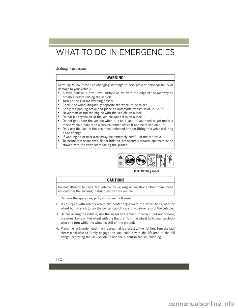
Jacking Instructions
WARNING!
Carefully follow these tire changing warnings to help prevent personal injury or
damage to your vehicle:
• Always park on a firm, level surface as far from the edge of the roadway as
possible before raising the vehicle.
• Turn on the Hazard Warning flasher.
• Chock the wheel diagonally opposite the wheel to be raised.
• Apply the parking brake and place an automatic transmission in PARK.
• Never start or run the engine with the vehicle on a jack.
• Do not let anyone sit in the vehicle when it is on a jack.
• Do not get under the vehicle when it is on a jack. If you need to get under a
raised vehicle, take it to a service center where it can be raised on a lift.
• Only use the jack in the positions indicated and for lifting this vehicle during
a tire change.
• If working on or near a roadway, be extremely careful of motor traffic.
• To assure that spare tires, flat or inflated, are securely stowed, spares must be
stowed with the valve stem facing the ground.
CAUTION!
Do not attempt to raise the vehicle by jacking on locations other than those
indicated in the Jacking Instructions for this vehicle.
1. Remove the spare tire, jack, and wheel bolt wrench.
2. If equipped with wheels where the center cap covers the wheel bolts, use the
wheel bolt wrench to pry the center cap off carefully before raising the vehicle.
3. Before raising the vehicle, use the wheel bolt wrench to loosen, but not remove,
the wheel bolts on the wheel with the flat tire. Turn the wheel bolts counterclock-
wise one turn while the wheel is still on the ground.
4. Place the jack underneath the lift area that is closest to the flat tire. Turn the jack
screw clockwise to firmly engage the jack saddle with the lift area of the sill
flange, centering the jack saddle inside the cutout in the sill cladding.
Jack Warning Label
WHAT TO DO IN EMERGENCIES
170
Page 175 of 220
9. Lower the vehicle to the ground by turning the jack handle counterclockwise.
10. Finish tightening the wheel bolts. Push down on the wrench while at the end of
the handle for increased leverage. Tighten the wheel bolts in a star pattern until
each wheel bolt has been tightened twice. The correct torque specification for
the wheel bolts is 63 Ft-Lbs (86 Nm) for steel wheels and 89 Ft-Lbs (120 Nm)
for aluminum wheels. If in doubt about the correct tightness, have them
checked with a torque wrench by your authorized dealer or at a service station.
11. Securely stow the jack, tools, chocks and flat tire.
WARNING!
A loose tire or jack thrown forward in a collision or hard stop could endanger the
occupants of the vehicle. Always stow the jack parts and the spare tire in the
places provided. Have the deflated (flat) tire repaired or replaced immediately.
Road Tire Installation
1. Mount the road tire on the axle.
2. Install the remaining wheel bolts with the threaded end of the wheel bolt toward
the wheel. Lightly tighten the wheel bolts.
WARNING!
To avoid the risk of forcing the vehicle off the jack, do not tighten the lug nuts fully
until the vehicle has been lowered. Failure to follow this warning may result in
serious injury.
3. Lower the vehicle to the ground by turning the jack handle counterclockwise.
4. Finish tightening the wheel bolts. Push down on the wrench while at the end ofthe handle for increased leverage. Tighten the wheel bolts in a star pattern untileach wheel bolt has been tightened twice. The correct torque specification for thewheel bolts is 63 Ft-Lbs (86 Nm) for steel wheels and 89 Ft-Lbs (120 Nm) foraluminum wheels. If in doubt about the correct tightness, have them checkedwith a torque wrench by your authorized dealer or at a service station.
5. Lower the jack until it is free. Remove the wheel chocks. Stow the jack and tools
back in the proper storage location. Release the Electric Park Brake before driving
the vehicle.
6. After 25 miles (40 km) check the wheel bolt torque with a torque wrench to
ensure that all wheel bolts are properly seated against the wheel.
WHAT TO DO IN EMERGENCIES
173
Page 178 of 220
6. Once the engine is started, remove the jumper cables in the reverse sequence:
Disconnecting The Jumper Cables
1. Disconnect the negative(-)end of the jumper cable from the engine ground of the
vehicle with the discharged battery.
2. Disconnect the opposite end of the negative(-)jumper cable from the negative(-)
post of the booster battery.
3. Disconnect the positive(+)end of the jumper cable from the positive(+)post of
the booster battery.
4. Disconnect the opposite end of the positive(+)jumper cable from the positive(+)
post of the vehicle with the discharged battery.
If frequent jump-starting is required to start your vehicle you should have the battery
and charging system inspected at your authorized dealer.
CAUTION!
Accessories plugged into the vehicle power outlets draw power from the vehicle’s
battery, even when not in use (i.e., cellular phones, etc.). Eventually, if plugged in
long enough without engine operation, the vehicle’s battery will discharge suffi-
ciently to degrade battery life and/or prevent the engine from starting.
FREEING A STUCK VEHICLE
If your vehicle becomes stuck in mud, sand or snow, it can often be moved using a
rocking motion. Turn the steering wheel right and left to clear the area around the
front wheels. For vehicles with automatic transmission, push and hold the lock
button on the shift lever. Then shift back and forth between DRIVE and REVERSE
(with automatic transmission) or 2ND GEAR and REVERSE (with manual transmis-
sion), while gently pushing the accelerator.
For Vehicles With Automatic Transmission:
Shifts between DRIVE and REVERSE can only be achieved at wheel speeds of 5 mph
(8 km/h) or less. Whenever the transmission remains in NEUTRAL for more than two
seconds, you must push the brake pedal to engage DRIVE or REVERSE.
Use the least amount of accelerator pedal pressure that will maintain the rocking
motion without spinning the wheels or racing the engine.
WHAT TO DO IN EMERGENCIES
176
Page 179 of 220
CAUTION!
• Racing the engine or spinning the wheels may lead to transmission overheatingand failure. Allow the engine to idle with the transmission in NEUTRAL for atleast one minute after every five rocking-motion cycles. This will minimizeoverheating and reduce the risk of clutch or transmission failure duringprolonged efforts to free a stuck vehicle.
• When “rocking” a stuck vehicle by shifting between DRIVE/2nd gear and
REVERSE, do not spin the wheels faster than 15 mph (24 km/h), or drivetrain
damage may result.
• Revving the engine or spinning the wheels too fast may lead to transmission
overheating and failure. It can also damage the tires. Do not spin the wheels
above 30 mph (48 km/h) while in gear (no transmission shifting occurring).
WARNING!
Fast spinning tires can be dangerous. Forces generated by excessive wheel speeds
may cause damage, or even failure, of the axle and tires. A tire could explode and
injure someone. Do not spin your vehicle's wheels faster than 30 mph (48 km/h)
or for longer than 30 seconds continuously without stopping when you are stuck
and do not let anyone near a spinning wheel, no matter what the speed.
EMERGENCY TOW HOOKS
If your vehicle is equipped with tow hooks, there will be one in the rear and two
mounted on the front of the vehicle. The rear hook will be located on the driver's side
of the vehicle.
NOTE:
For off-road recovery, it is recommended to use both of the front tow hooks to
minimize the risk of damage to the vehicle.
Vehicles Equipped With RKE Transmitter With An Integrated Vehicle Key
Turn the ignition key to the MAR/RUN and then STOP/OFF position, without
removing it. By extracting the key this will automatically engage the steering wheel
lock. Place the transmission into NEUTRAL.
Vehicles With Keyless Enter-N-Go™
Place the ignition in the RUN and subsequently on STOP, without opening the door.
During towing remember that not having the aid of the power brakes and the
electromechanical power steering, greater force is needed in applying the brakes and
steering of the vehicle.
WHAT TO DO IN EMERGENCIES
177
Page 183 of 220
TO OPEN AND CLOSE THE HOOD
Opening
Two latches must be released to open the hood.
Pull the hood release lever located under the drivers side of the instrument panel.
Move to the outside of the vehicle and push the safety latch release lever toward the
passenger side of the vehicle. The hood release lever is located behind the center
front edge of the hood.
Remove the support rod from the locking tab and insert it into the seat located on the
underside of the hood.
Closing
Hold up the hood with one hand and with the other hand remove the support rod from
its seat and reinsert it into the locking tab.
Lower the hood to approximately 6 inches (15 cm) from the engine compartment and
drop it. Make sure that the hood is completely closed.
CAUTION!
To prevent possible damage, do not slam the hood to close it. Lower the hood until
it is open approximately 6 inches (15 cm), and then drop it. This should secure
both latches. Never drive your vehicle unless the hood is fully closed, with both
latches engaged.
WARNING!
Be sure the hood is fully latched before driving your vehicle. If the hood is not fully
latched, it could open when the vehicle is in motion and block your vision. Failure
to follow this warning could result in serious injury or death.
MAINTAINING YOUR VEHICLE
181