lock JEEP RENEGADE 2015 1.G Owner's Manual
[x] Cancel search | Manufacturer: JEEP, Model Year: 2015, Model line: RENEGADE, Model: JEEP RENEGADE 2015 1.GPages: 220, PDF Size: 34.11 MB
Page 25 of 220
Center Seat LATCH
Do not install a child restraint in the center position using the LATCH system. Use the
seat belt and tether anchor to install a child seat in the center seating position.
Installing The Child Restraint Using The LATCH Lower Anchors
NOTE:
Never“share” a LATCH anchorage with two or more child restraints.
1. Loosen the adjusters on the lower straps and on the tether strap of the child seat
so that you can more easily attach the hooks or connectors to the vehicle
anchorages.
2. Attach the lower hooks or connectors of the child restraint to the lower anchorages
in the selected seating position.
3. If the child restraint has a tether strap, connect it to the top tether anchorage. See
below for directions to attach a tether anchor.
4. Tighten all of the straps as you push the child restraint rearward and downward
into the seat. Remove slack in the straps according to the child restraint
manufacturer’s instructions.
5. Test that the child restraint is installed tightly by pulling back and forth on the
child seat at the belt path. It should not move more than 1 inch (25.4 mm) in any
direction.
Installing The Child Restraint Using The Vehicle Seat Belts
The seat belts in the passenger seating positions are equipped with a Switchable
Automatic Locking Retractor (ALR) that is designed to keep the lap portion of the
seat belt tight around the child restraint. Any seat belt system will loosen with time,
so check the belt occasionally, and pull it tight if necessary.
Tether Weight Limit
Always use the tether anchor when using the seat belt to install a forward facing child
restraint, up to the recommended weight limit of the child restraint.
GETTING STARTED
23
Page 26 of 220
To Install A Child Seat Using An ALR:
1. Pull enough of the seat belt webbing from the retractor to pass it through the belt
path of the child restraint. Do not twist the belt webbing in the belt path.
2. Slide the latch plate into the buckle until you hear a “click.”
3. Pull on the webbing to make the lap portion tight against the child seat.
4. To lock the seat belt, pull down on the shoulder part of the belt until you have
pulled all the seat belt webbing out of the retractor. Then, allow the webbing to
retract back into the retractor. As the webbing retracts, you will hear a clicking
sound. This means the seat belt is now in the Automatic Locking mode.
5. Try to pull the webbing out of the retractor. If it is locked, you should not be able
to pull out any webbing. If the retractor is not locked, repeat the last step.
6. Finally, pull up on any extra webbing to tighten the lap portion around the child
restraint while you push the child restraint rearward and downward into the
vehicle seat.
7. If the child restraint has a top tether strap and the seating position has a top tether
anchorage, connect the tether strap to the anchorage and tighten the tether strap.
See below for directions to attach a tether anchor.
8. Test that the child restraint is installed tightly by pulling back and forth on the
child seat at the belt path. It should not move more than 1 inch (25.4 mm) in any
direction.
Installing The Top Tether Strap (With Either Lower Anchors Or Vehicle Seat
Belt):
When installing a forward-facing child restraint, always secure the top tether strap,
up to the tether anchor weight limit, whether the child restraint is installed with the
lower anchors or the vehicle seat belt.
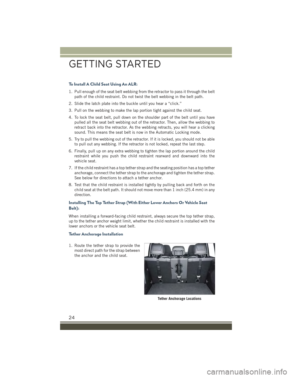
Tether Anchorage Installation
1. Route the tether strap to provide the
most direct path for the strap between
the anchor and the child seat.
Tether Anchorage Locations
GETTING STARTED
24
Page 34 of 220
Seatback Repositioning
NOTE:
If interference from the cargo area prevents the seatback from fully locking, you will
have difficulty returning the seat to its proper position.
1. Move the safety belts to the seat belt guides on the top edge of the seat to ensure
the seatbacks properly latch.
2. Lift the seatbacks, pushing them back until they lock on both the latches. Verify
the red notches are no longer visible on the release lever. If the red notches are
visible, the seatback is not secure.
Unfolding The Rear Armrest 40/20/40
Tilt the head restraint forward and pull the rear armrest tab to release it from the seat
and pull forward.
The center part of the rear seat can also be used as rear armrest with cupholders.
WARNING!
Be certain that the seatback is securely locked into position. If the seatback is not
securely locked into position the seat will not provide the proper stability for child
seats and/or passengers. An improperly latched seat could cause serious injury.
HEATED STEERING WHEEL
The steering wheel contains a heating element that helps warm your hands in cold
weather. The heated steering wheel has only one temperature setting. Once the
heated steering wheel switchhas been turned on, it will operate for up to 80
minutes before automatically shutting off. The heated steering wheel can shut off
early or may not turn on when the steering wheel is already warm. The heated steering
wheel control button is located on the center of the instrument panel below the radio
screen.
WARNING!
• Persons who are unable to feel pain to the skin because of advanced age,
chronic illness, diabetes, spinal cord injury, medication, alcohol use, exhaus-
tion, or other physical conditions must exercise care when using the steering
wheel heater. It may cause burns even at low temperatures, especially if used
for long periods.
• Do not place anything on the steering wheel that insulates against heat, such
as a blanket or steering wheel covers of any type and material. This may cause
the steering wheel heater to overheat.
GETTING STARTED
32
Page 35 of 220
TILT/TELESCOPING STEERING COLUMN
This feature allows you to tilt the steering column upward or downward. It also allows
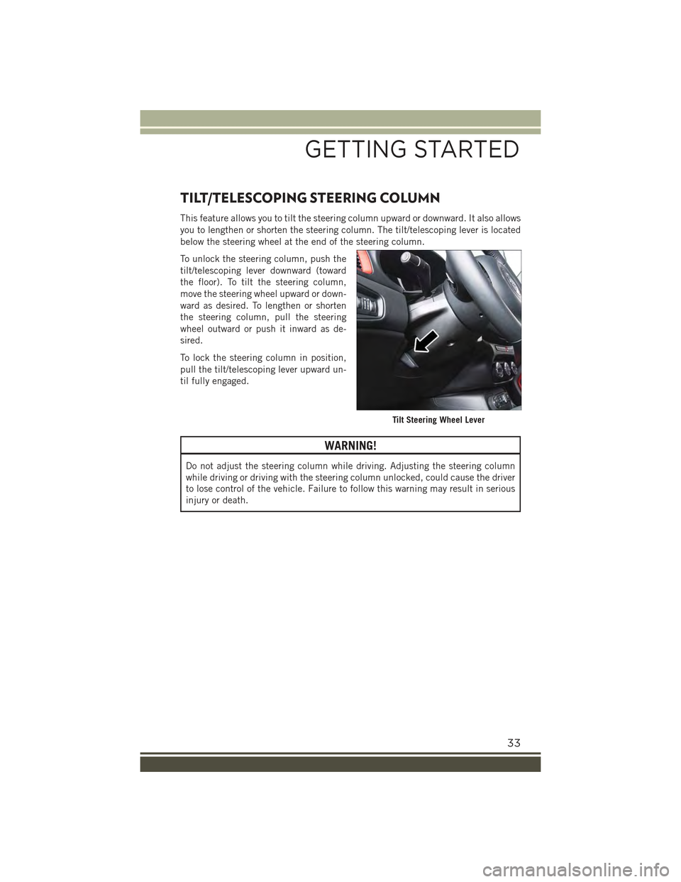
you to lengthen or shorten the steering column. The tilt/telescoping lever is located
below the steering wheel at the end of the steering column.
To unlock the steering column, push the
tilt/telescoping lever downward (toward
the floor). To tilt the steering column,
move the steering wheel upward or down-
ward as desired. To lengthen or shorten
the steering column, pull the steering
wheel outward or push it inward as de-
sired.
To lock the steering column in position,
pull the tilt/telescoping lever upward un-
til fully engaged.
WARNING!
Do not adjust the steering column while driving. Adjusting the steering column
while driving or driving with the steering column unlocked, could cause the driver
to lose control of the vehicle. Failure to follow this warning may result in serious
injury or death.
Tilt Steering Wheel Lever
GETTING STARTED
33
Page 49 of 220
WARNING!
• Never use the PARK position as a substitute for the parking brake. Always apply
the parking brake fully when parked to guard against vehicle movement and
possible injury or damage.
• When leaving the vehicle, always make sure the keyless ignition node is in the
“STOP/OFF” mode, remove the Key Fob from the vehicle and lock the vehicle.
• Never leave children alone in a vehicle, or with access to an unlocked vehicle.
Allowing children to be in a vehicle unattended is dangerous for a number of
reasons. A child or others could be seriously or fatally injured. Children should
be warned not to touch the parking brake, brake pedal or the shift lever.
• Do not leave the Key Fob in or near the vehicle, or in a location accessible to
children, and do not leave a vehicle equipped with Keyless Enter-N-Go™in the
MAR/RUN mode. A child could operate power windows, other controls, or move
the vehicle.
• Be sure the parking brake is fully disengaged before driving; failure to do so can
lead to brake failure and a collision.
• Always fully apply the parking brake when leaving your vehicle, or it may roll
and cause damage or injury. Also be certain to leave the transmission in PARK.
Failure to do so may allow the vehicle to roll and cause damage or injury.
BLIND SPOT MONITORING (BSM)
The Blind Spot Monitoring (BSM) system uses two radar-based sensors, located
inside the rear bumper fascia, to detect highway licensable vehicles (automobiles,
trucks, motorcycles, etc.) that enter the blind spot zones from the rear/front/side of
the vehicle.
When the vehicle is started, the BSM warning light will momentarily illuminate in
both outside rear view mirrors to let the driver know that the system is operational.
The BSM system sensors operate when the vehicle is in any forward gear or REVERSE
and enters stand-by mode when the vehicle is in PARK.
The BSM detection zone covers approximately one lane width on both sides of the
vehicle, 10 ft (3 m). The zone length starts at the outside mirror and extends
approximately 20 ft (6 m) beyond the rear bumper of the vehicle. The BSM system
monitors the detection zones on both sides of the vehicle when the vehicle speed
reaches approximately 6 mph (10 km/h) or higher and will alert the driver of vehicles
in these areas.
OPERATING YOUR VEHICLE
47
Page 50 of 220
NOTE:
• The BSM system does NOT alert the driver about rapidly approaching vehicles that
are outside the detection zones.
• The BSM system detection zone DOES NOT change if your vehicle is towing a
trailer. Therefore, visually verify the adjacent lane is clear for both your vehicle and
trailer before making a lane change. If the trailer or other object (i.e., bicycle,
sports equipment) extends beyond the side of your vehicle, this may result in the
BSM warning light remaining illuminated the entire time the vehicle is in a forward
gear. It may be necessary to deactivate BSM system manually by related menu to
avoid a miss-detection.
The area on the rear fascia where the radar sensors are located must remain free of
snow, ice, and dirt/road contamination so that the BSM system can function properly.
Do not block the radar sensors located on the rear fascia with foreign objects (bumper
stickers, bicycle racks, etc.).
The BSM system notifies the driver of objects in the detection zones by illuminating
the BSM warning light located in the outside mirrors in addition to sounding an
audible (chime) alert and reducing the radio volume.
The BSM system monitors the detection zone from three different entry points (side,
rear, front) while driving to see if an alert is necessary. The BSM system will issue an
alert during these types of zone entries.
Entering From The Side
Vehicles that move into your adjacent lanes from either side of the vehicle.
Entering From The Rear
Vehicles that come up from behind your vehicle on either side and enter the rear
detection zone with a relative speed of less than 31 mph (50 km/h).
Overtaking Traffic
If you pass another vehicle slowly with a relative speed less than 15 mph (25 km/h)
and the vehicle remains in the blind spot for approximately 1.5 seconds, the warning
light will be illuminated. If the difference in speed between the two vehicles is
greater than 15 mph (25 km/h), the warning light will not illuminate.
The BSM system is designed not to issue an alert on stationary objects such as
guardrails, posts, walls, foliage, berms, etc. However, occasionally the system may
alert on such objects. This is normal operation and your vehicle does not require
service.
The BSM system will not alert you of objects that are traveling in the opposite
direction of the vehicle in adjacent lanes.
OPERATING YOUR VEHICLE
48
Page 51 of 220
WARNING!
The Blind Spot Monitoring system is only an aid to help detect objects in the blind
spot zones. The BSM system is not designed to detect pedestrians, bicyclists, or
animals. Even if your vehicle is equipped with the BSM system, always check your
vehicles mirrors, glance over your shoulder, and use your turn signal before
changing lanes. Failure to do so can result in serious injury or death.
Rear Cross Path (RCP)
The Rear Cross Path (RCP) feature is intended to aid the driver when backing out of
parking spaces where their vision of oncoming vehicles may be blocked. Proceed
slowly and cautiously out of the parking space until the rear end of the vehicle is
exposed. The RCP system will then have a clear view of the cross traffic and if an
oncoming vehicle is detected, alert the driver.
RCP monitors the rear detection zones on both sides of the vehicle, for objects that
are moving toward the side of the vehicle with a minimum speed of approximately
1 mph (2 km/h), to objects moving a maximum of approximately 22 mph (35 km/h),
such as in parking lot situations.
NOTE:
In a parking lot situation, oncoming vehicles can be obscured by vehicles parked on
either side. If the sensors are blocked by other structures or vehicles, the system will
not be able to alert the driver.
When RCP is on and the vehicle is in REVERSE, the driver is alerted using both the
visual and audible alarms, including reducing the radio volume.
WARNING!
RCP is not a Back Up Aid system. It is intended to be used to help a driver detect
an oncoming vehicle in a parking lot situation. Drivers must be careful when
backing up, even when using RCP. Always check carefully behind your vehicle,
look behind you, and be sure to check for pedestrians, animals, other vehicles,
obstructions, and blind spots before backing up. Failure to do so can result in
serious injury or death.
OPERATING YOUR VEHICLE
49
Page 56 of 220
“Wipe Front Radar Sensor In Front Of Vehicle” Warning
The “FCW Unavailable Wipe Front Radar Sensor” warning will display when condi-
tions temporarily limit system performance. This most often occurs at times of poor
visibility, such as in snow or heavy rain. The system may also become temporarily
blinded due to obstructions, such as mud, dirt or ice. In these cases, the EVIC/DID
will display “ FCW Unavailable Wipe Front Radar Sensor” and the system will
deactivate.
The “FCW Unavailable Wipe Front Radar Sensor” message can sometimes be
displayed while driving in highly reflective areas (i.e. tunnels with reflective tiles, or
ice and snow). The system will recover after the vehicle has left these areas. Under
rare conditions, when the radar is not tracking any vehicles or objects in its path this
warning may temporarily occur.
If weather conditions are not a factor, the driver should examine the sensor. It may
require cleaning or removal of an obstruction. The sensor is located behind the lower
grille.
NOTE:
• If the “FCW Unavailable Wipe Front Radar Sensor” message occurs frequently
(e.g. more than once on every trip) without any snow, rain, mud, or other
obstruction, have the radar sensor realigned at your authorized dealer.
• Installing a snow plow, front-end protector, an aftermarket grille or modifying the
grille is not recommended. Doing so may block the sensor and inhibit FCW
operation.
Precautions While Driving With FCW
In certain driving conditions, such as:
• Driving in the vicinity of a curve
• Small vehicles and/or not aligned to the lane
• Lane changing of other vehicles
• Passing of vehicles in an oncoming intersection
The intervention of the system could be unexpected or delayed. The driver must
therefore always pay particular attention, while maintaining control of the car to drive
in complete safety.
Driving In The Vicinity Of A Curve
Entering or exiting a large curve, the system could detect the presence of a vehicle
that is in front of the car, but that does not preside in the same lane. In cases such
as this, the system might respond.
OPERATING YOUR VEHICLE
54
Page 60 of 220
• When the LaneSense system senses the lane has been approached and is in a lane
departure situation, the left thick lane line flashes yellow (on/off) and the left thin
line remains solid yellow. The LaneSense indicator changes from solid yellow to
flashing yellow. At this time torque is applied to the steering wheel in the opposite
direction of the lane boundary.
For example: If approaching the left side of the lane the steering wheel will turn to the
right.
NOTE:
The LaneSense system operates with the similar behavior for a right lane departure.
Changing LaneSense Status
The LaneSense system has settings to adjust the intensity of the torque warning and
the warning zone sensitivity (early/late) that you can configure through the
Uconnect®system screen.
NOTE:
• When enabled the system operates above 37 mph (60 km/h) and below 112 mph
(180 km/h).
• Use of the turn signal suppresses the warnings.
• The system will not apply torque to the steering wheel whenever a safety system
engages. (anti-lock brakes, traction control system, electronic stability control,
forward collision warning, etc.).
PARKSENSE® REAR PARK ASSIST
The ParkSense®Rear Park Assist system provides visual and audible indications of
the distance between the rear fascia and a detected obstacle when backing up, e.g.
during a parking maneuver.
ParkSense®will retain the last system state (enabled or disabled) from the last
ignition cycle when the ignition is changed to the MAR/RUN position.
ParkSense®can be active only when the shift lever/gear selector is in REVERSE. If
ParkSense®is enabled at this shift lever position, the system will remain active until
the vehicle speed is increased to approximately 7 mph (11 km/h) or above. When in
REVERSE and above the system's operating speed, a warning will appear within the
Electronic Vehicle Information Center (EVIC) or Driver Information Display (DID).
OPERATING YOUR VEHICLE
58
Page 68 of 220
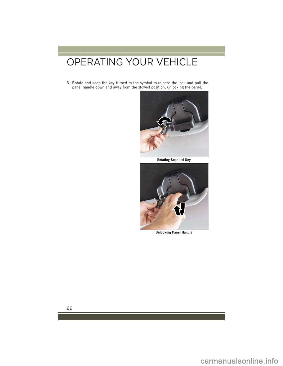
3. Rotate and keep the key turned to the symbol to release the lock and pull thepanel handle down and away from the stowed position, unlocking the panel.
Rotating Supplied Key
Unlocking Panel Handle
OPERATING YOUR VEHICLE
66