steering JEEP RENEGADE 2018 Owner handbook (in English)
[x] Cancel search | Manufacturer: JEEP, Model Year: 2018, Model line: RENEGADE, Model: JEEP RENEGADE 2018Pages: 356, PDF Size: 6.11 MB
Page 165 of 356

ADAPTIVE CRUISE
CONTROL (ACC)
(where provided)
134) 135) 136) 137) 138) 139)
54) 55) 56) 57) 58) 59) 60)
DESCRIPTION
The Adaptive Cruise Control (ACC) is a
driver assist device which combines the
Cruise Control functions with one for
controlling the distance from the vehicle
ahead.
The Adaptive Cruise Control (ACC) uses a
radar sensor, located behind the front
bumper fig. 115 and a camera, located
in the middle of the windscreen fig. 116,
to detect the presence of a vehicle close
ahead.
There are two operating modes:
“Adaptive Cruise Control”mode to
maintain an adequate distance between
vehicles (the message “Adaptive CruiseControl” is shown on the instrument
panel display);
electronic “Cruise Control” modeto hold the vehicle at a constant
preset speed.
To change the operation mode, use the
button on the steering wheel (see that
described on the following pages).
ADAPTIVE CRUISE CONTROL
ACTIVATION/DEACTIVATION
Activation
To activate the device, press and release
the
button. fig. 117
The device cannot be activated when
4WD LOW is engaged.115J0A0334C
116J0A0241C117J0A0917C
163
Page 175 of 356
PARALLEL AND
PERPENDICULAR PARKING
DESCRIPTION
Activation
The system is activated pressing the
button on the dashboard (see "On/off"
paragraph): after being selected, the
system activates in search mode.
Considering that the system recognises
parking places even when it has not been
selected, it can be activated even
immediately after passing close to a
parking place suitable for the type of car.
The system will inform the driver,
through the instrument panel display,
about the operations to be performed for
a correct manoeuvre.
Selecting the type of parking
During the search and until the reverse
gear is engaged, the preferred type can
be selected for parking:
"Parallel": the car will search a parking
place parallel to the driving direction;
"Perpendicular": the vehicle will
search a parking place perpendicular to
the driving direction.
Selection of the search side
To select the search side and perform the
correct manoeuvre, act as follows:
Select the search for the parking
place and the manoeuvre on thepassenger side placing the direction
indicator in centre position (deactivated)
or pushed upwards.
Select the search for the parking
area and manoeuvre on the driver side
pushing the direction indicator
downwards.
Search for a parking place
Through the side sensors, the system
continuously searches for a free parking
place, suitable for the car’s dimensions.
While searching the vehicle should
continue following its route at a speed of
below 30 km/h and at a distance of
around 50 cm to 1.5 m from parked
vehicles.
A parking place is considered suitable if
it is about 80 cm longer than the
dimensions of the vehicle for parking
placesparallelto the driving direction
and about 1 m per parking places
perpendicularto the driving direction,
compared to the vehicle's dimensions.
IMPORTANT While searching, vehicle
speed should not exceed 30 km/h;
when 25 km/h have been reached, the
driver is asked to decrease the speed;
if the speed of 30 km/h is exceeded, it
is deactivated (in this case, the system
can be restarted by pressing the button
on the instrument panel).
Manoeuvre
During manoeuvre, the vehicle's
movements can be controlled by
operating the accelerator, brake and
clutch pedals (versions with manual
gearbox), or the accelerator and brake
pedals (versions with automatic
transmission). Once a parking place has
been found, you will be asked to engage
reverse, leave the steering wheel and use
the pedals, while the system handles the
steering automatically to perform the
parking operation in the dedicated area.
During the manoeuvre it will be possible
to take advantage of the information
coming from the parking sensors (when
driving in reverse it is advisable to reach
the area where the rear sensors sound
continuously), but it is always advisable
to keep an eye on the surrounding area.
The car can be stopped during the
manoeuvre and, whilst remaining
stationary, reverse gear can temporarily
be released (for example, to allow a
pedestrian to go by in the area of the
manoeuvre).
The parking manoeuvre will be
interrupted in the following cases:
vehicle's speed is above 7 km/h;the steering is (voluntarily or
unintentionally) moved (by grabbing it or
preventing it from moving);
173
Page 177 of 356
IMPORTANT Some messages displayed
are accompanied by acoustic warnings.
WARNING
141)Parking and other dangerous
manoeuvres are, however, always the
driver’s responsibility. While carrying out
these manoeuvres, always make sure that
no people (especially children) or animals
are in the area concerned. The parking
sensors are an aid for the driver, but the
driver must never allow their attention to
lapse during potentially dangerous
manoeuvres, even those executed at low
speeds.
142)The search for the parking space and
the parking manoeuvres must be
performed in compliance with the current
regulations of the Highway Code.
143)If you wish to stop the steering wheel
with your hands during a manoeuvre, it is
advisable to handle it firmly on the outer
rim. Do not try and keep your hands on
the inside or hold the spokes.
IMPORTANT
64)The operation of the system is based
on various components: front and rear
parking sensors, side sensors, steering
system, wheels, braking system and
instrument panel. The malfunction of one
of these components could compromise
the operation of the system.
65)Only have the bumpers repainted or
any retouches to the paintwork in the area
of the sensors carried out by a Jeep
Dealership. Incorrect paint application
could affect the operation of the parking
sensors.
175
Page 180 of 356
LANESENSE SYSTEM (lane
crossing warning)
DESCRIPTION
68) 69) 70) 71) 72) 73)
The LaneSense system makes use of a
camera located on the windscreen to
detect the lane limits and calculate the
position of the vehicle within such limits,
in order to make sure that it remains
inside the lane.
When both limits of the lane are detected
and the vehicle crosses one of them
without the awareness of the driver
(direction indicator off), the system
provides a tactile warning by applying
torque to the steering wheel, signalling
the driver that he must take an action to
remain into the lane.
If the vehicle continues going beyond the
line of the lane without any intervention
from the driver, the
warning light (or
the corresponding graphic icon on the
reconfigurable multifunction display) will
be displayed on the instrument panel to
urge the driver to bring the vehicle back
into the limits of the lane.
IMPORTANT The system monitors the
presence of the driver's hands on the
steering wheel. If they are not detected,the system emits an acoustic signal and
deactivates until it is reactivated by
pressing the dedicated button.
When one limit of the lane is detected
and the vehicle crosses it (direction
indicator off), warning light
(or the
icon on the reconfigurable multifunction
display) will be displayed on the
instrument panel to urge the driver to
bring the vehicle back into the lane. In
this case, the tactile warning (torque on
the steering wheel) is not provided.
SYSTEM ON/OFF
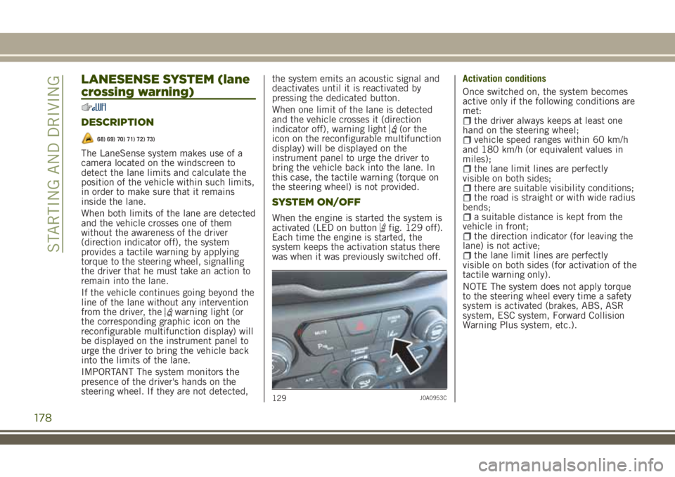
When the engine is started the system is
activated (LED on buttonfig. 129 off).
Each time the engine is started, the
system keeps the activation status there
was when it was previously switched off.Activation conditions
Once switched on, the system becomes
active only if the following conditions are
met:
the driver always keeps at least one
hand on the steering wheel;
vehicle speed ranges within 60 km/h
and 180 km/h (or equivalent values in
miles);
the lane limit lines are perfectly
visible on both sides;
there are suitable visibility conditions;the road is straight or with wide radius
bends;
a suitable distance is kept from the
vehicle in front;
the direction indicator (for leaving the
lane) is not active;
the lane limit lines are perfectly
visible on both sides (for activation of the
tactile warning only).
NOTE The system does not apply torque
to the steering wheel every time a safety
system is activated (brakes, ABS, ASR
system, ESC system, Forward Collision
Warning Plus system, etc.).
129J0A0953C
178
STARTING AND DRIVING
Page 182 of 356
SYMBOLS AND MESSAGES ON
THE DISPLAY
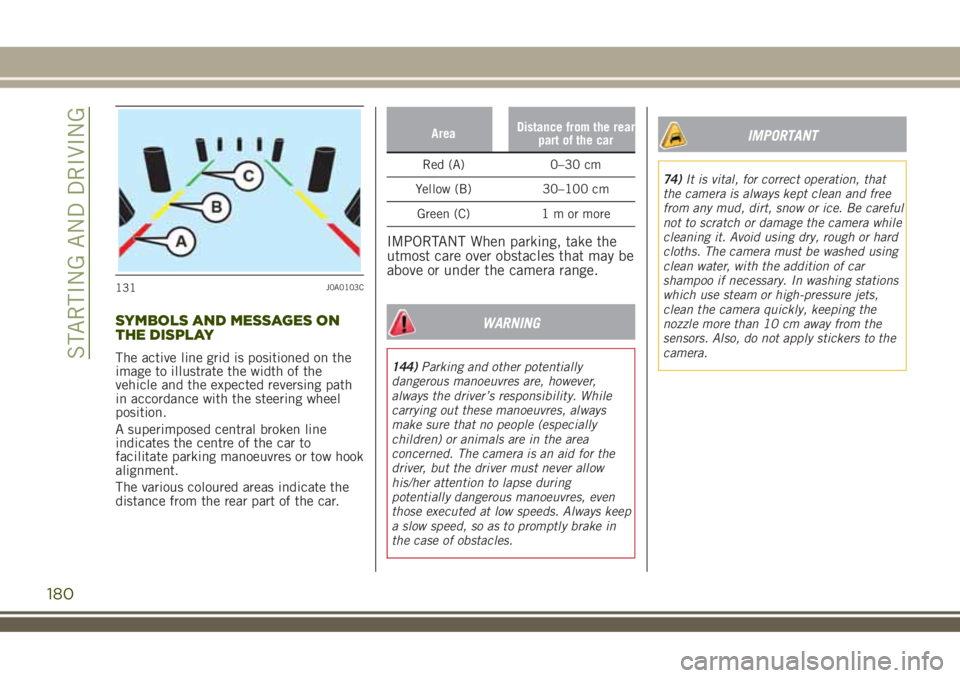
The active line grid is positioned on the
image to illustrate the width of the
vehicle and the expected reversing path
in accordance with the steering wheel
position.
A superimposed central broken line
indicates the centre of the car to
facilitate parking manoeuvres or tow hook
alignment.
The various coloured areas indicate the
distance from the rear part of the car.
AreaDistance from the rear
part of the car
Red (A) 0–30 cm
Yellow (B) 30–100 cm
Green (C) 1 m or more
IMPORTANT When parking, take the
utmost care over obstacles that may be
above or under the camera range.
WARNING
144)Parking and other potentially
dangerous manoeuvres are, however,
always the driver’s responsibility. While
carrying out these manoeuvres, always
make sure that no people (especially
children) or animals are in the area
concerned. The camera is an aid for the
driver, but the driver must never allow
his/her attention to lapse during
potentially dangerous manoeuvres, even
those executed at low speeds. Always keep
a slow speed, so as to promptly brake in
the case of obstacles.
IMPORTANT
74)It is vital, for correct operation, that
the camera is always kept clean and free
from any mud, dirt, snow or ice. Be careful
not to scratch or damage the camera while
cleaning it. Avoid using dry, rough or hard
cloths. The camera must be washed using
clean water, with the addition of car
shampoo if necessary. In washing stations
which use steam or high-pressure jets,
clean the camera quickly, keeping the
nozzle more than 10 cm away from the
sensors. Also, do not apply stickers to the
camera.
131J0A0103C
180
STARTING AND DRIVING
Page 206 of 356
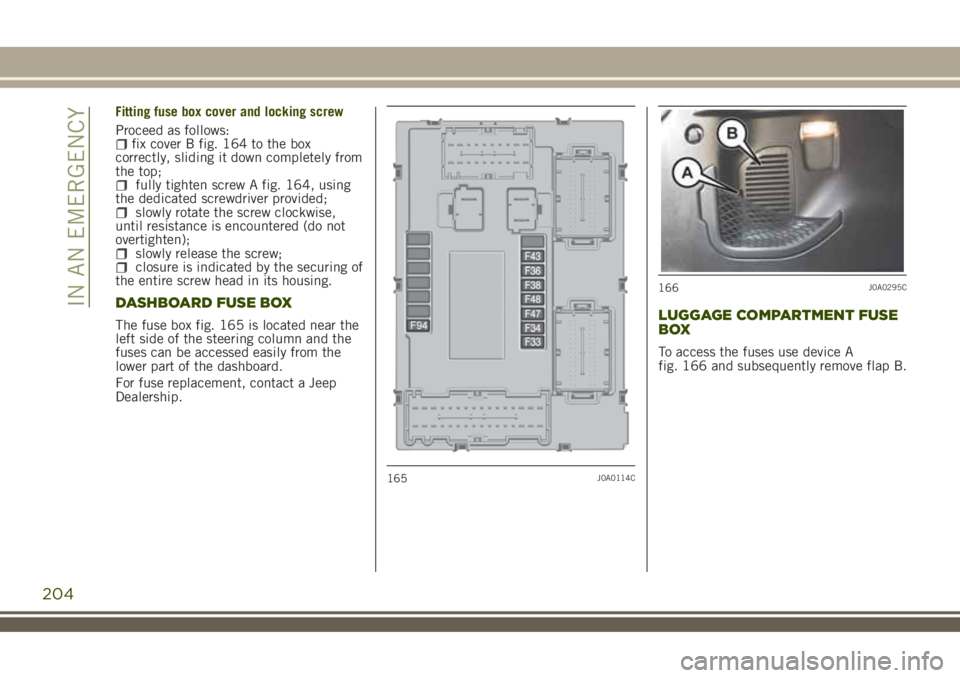
Fitting fuse box cover and locking screw
Proceed as follows:
fix cover B fig. 164 to the box
correctly, sliding it down completely from
the top;
fully tighten screw A fig. 164, using
the dedicated screwdriver provided;
slowly rotate the screw clockwise,
until resistance is encountered (do not
overtighten);
slowly release the screw;closure is indicated by the securing of
the entire screw head in its housing.
DASHBOARD FUSE BOX
The fuse box fig. 165 is located near the
left side of the steering column and the
fuses can be accessed easily from the
lower part of the dashboard.
For fuse replacement, contact a Jeep
Dealership.LUGGAGE COMPARTMENT FUSE
BOX
To access the fuses use device A
fig. 166 and subsequently remove flap B.
165J0A0114C
166J0A0295C
204
IN AN EMERGENCY
Page 211 of 356
WARNING
154)If the replaced fuse blows again,
contact a Jeep Dealership.
155)Never replace a fuse with another
with a higher amp rating; DANGER OF
FIRE.
156)If a general fuse (MAXI-FUSE,
MEGA-FUSE, MIDI-FUSE) cuts in, do not
attempt any repair and contact a Jeep
Dealership.
157)Before replacing a fuse, make sure
that the ignition device is at STOP, that
the key, if mechanical, has been removed
and that all devices are switched off
and/or disconnected.
158)If a general protection fuse for safety
systems (airbag system, braking system),
power unit systems (engine system,
transmission system) or steering system
blows, contact a Jeep Dealership.
IMPORTANT
77)Never replace a fuse with metal wires
or anything else.
78)If it is necessary to wash the engine
compartment, take care not to directly hit
the fuse box and the window wiper motors
with the water jet.
CHANGING A WHEEL
159) 160) 161) 162) 163) 166) 167)
JACK
164) 165)
Please note that:the weight of the jack is 2.8 kg;the jack requires no adjustment;the jack cannot be repaired and in the
event of a fault it must be replaced by
another genuine one;
no tool other than its cranking device
may be fitted on the jack.
Maintenance
prevent any dirt from depositing on
the "worm screw";
keep the "worm screw" lubricated;never modify the jack.
Conditions for non-use
temperatures below −40°C;on sandy or muddy ground;on uneven ground;on steep roads;in extreme weather conditions:
thunderstorms, typhoons, hurricanes,
blizzards, storms, etc...
in direct contact with the engine or for
repairs under the car;
on boats.
209
Page 216 of 356
214
IN AN EMERGENCY
162)The vehicle's driving characteristics
will be modified with the space-saver
wheel fitted. Avoid violent acceleration
and braking, abrupt steering and fast
cornering. The overall duration of the
space-saver wheel is about 3000 km, after
which the relevant tyre must be replaced
with another one of the same type. Never
install a standard tyre on a rim that is
designed for use with a space-saver wheel.
Have the wheel repaired and refitted as
soon as possible. Using two or more
space-saver wheels at the same time is
forbidden. Do not grease the threads of
the stud bolts before fitting them: they
might slip out when driving!
163)The space-saver wheel (where
provided) is specific to your vehicle: do
not use it on other models, or use the
space-saver wheel of other models on your
vehicle. The space-saver wheel must only
be used in the event of an emergency.
Never use it for more than strictly
necessary and never exceed 80 km/h. On
the space-saver wheel there is an orange
label, summarising the main warnings
regarding space-saver wheel usage
restrictions. Never remove or cover the
label. Never apply a wheel cap on a
space-saver wheel.164)The jack is a tool developed and
designed only for changing a wheel, if a
tyre gets punctured or damaged, on the
vehicle with which it is supplied or on
other vehicles of the same model. Any
other use, e.g. to jack up other vehicle
models or different things, is strictly
prohibited. Never use it to carry out
servicing or repairs under the vehicle or to
change summer/winter wheels and vice
versa: we advise you to contact a Jeep
Dealership. Never go under the raised
vehicle: use it only in the positions
indicated. Do not use the jack for loads
higher than the one shown on its label.
Never start the engine with car raised. If
the vehicle is raised more than necessary,
everything can become more unstable,
with the risk of the vehicle dropping
violently. Thus, lift the car only as needed
in order to access the space-saver spare
wheel.
165)When turning the jack handle make
sure that it can turn freely without
scraping your hand against the ground.
The moving components of the jack
("worm screw" and joints) can also cause
injuries: do not touch them. If you come
into contact with lubricating grease, clean
yourself thoroughly.166)The space-saver wheel cannot be
fitted with snow chains. If a front (drive)
tyre is punctured and chains are needed,
use a standard wheel from the rear axle
and install the space-saver wheel on the
rear axle. In this way, with two normal
drive wheels at the front axle, it is
possible to use snow chains.
167)Incorrect hub cap assembly, if
present, may cause it to come off when
the vehicle is moving. Never tamper with
the inflation valve. Never introduce tools
of any kind between the rim and the tyre.
Check tyre and space-saver wheel
pressures regularly, complying with the
values given in the "Technical
specifications" chapter.
Page 223 of 356
fully depress the brake pedal and hold
it down;
insert the screwdriver supplied
perpendicularly in hole B fig. 184 and
adjust the release lever;
place the gear lever in N (Neutral)
position;
refit the gear lever gaiter and panel
correctly;
start the engine.
EMERGENCY REMOVAL OF THE
IGNITION KEY
81)
The ignition key (versions with
mechanical key) can be removed only if
the gear lever is in position P (Park).
If the vehicle battery is flat and the key
is engaged, the latter is locked in
position.
To remove the key manually, proceed as
follows:
stop the vehicle in safety conditions,
engage a gear and the electric parking
brake;
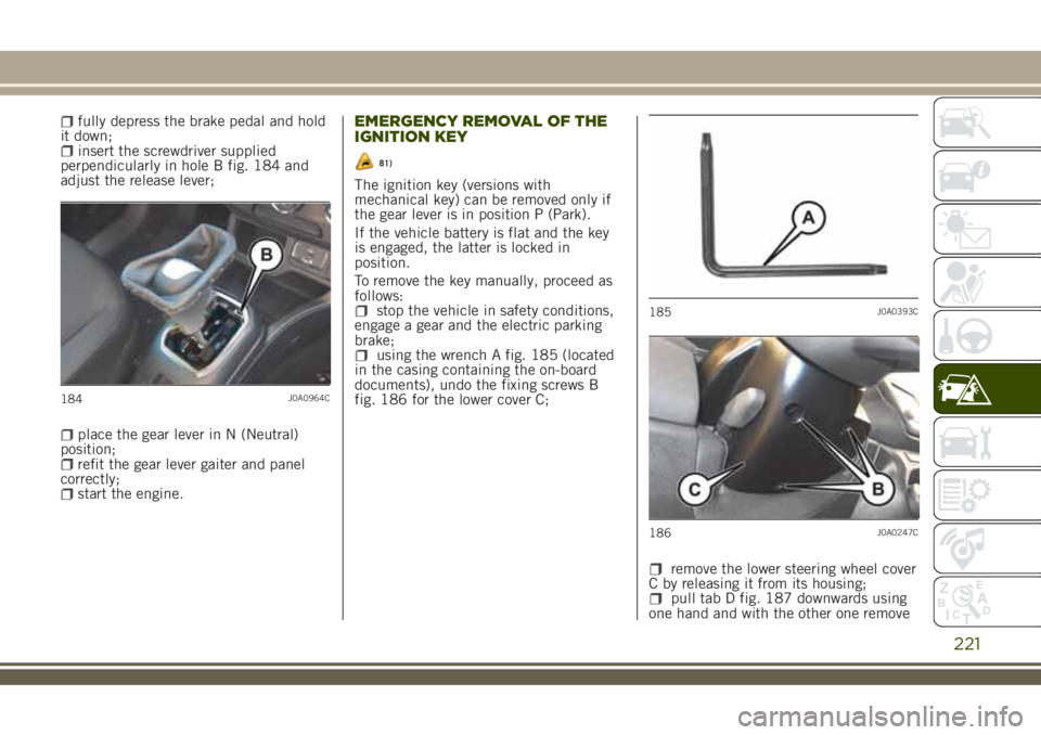
using the wrench A fig. 185 (located
in the casing containing the on-board
documents), undo the fixing screws B
fig. 186 for the lower cover C;
remove the lower steering wheel cover
C by releasing it from its housing;
pull tab D fig. 187 downwards using
one hand and with the other one remove
184J0A0964C
185J0A0393C
186J0A0247C
221
Page 225 of 356
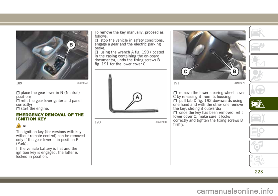
place the gear lever in N (Neutral)
position;
refit the gear lever gaiter and panel
correctly;
start the engine.
EMERGENCY REMOVAL OF THE
IGNITION KEY
82)
The ignition key (for versions with key
without remote control) can be removed
only if the gear lever is in position P
(Park).
If the vehicle battery is flat and the
ignition key is engaged, the latter is
locked in position.To remove the key manually, proceed as
follows:
stop the vehicle in safety conditions,
engage a gear and the electric parking
brake;
using the wrench A fig. 190 (located
in the casing containing the on-board
documents), undo the fixing screws B
fig. 191 for the lower cover C;
remove the lower steering wheel cover
C by releasing it from its housing;
pull tab D fig. 192 downwards using
one hand and with the other one remove
the key, sliding it outwards;
once the key has been removed, refit
lower cover C, make sure it locks
correctly and tighten the fixing screws B
firmly.
189J0A0964C
190J0A0393C
191J0A0247C
223