brake JEEP RENEGADE 2018 Owner handbook (in English)
[x] Cancel search | Manufacturer: JEEP, Model Year: 2018, Model line: RENEGADE, Model: JEEP RENEGADE 2018Pages: 356, PDF Size: 6.11 MB
Page 183 of 356
REFUELLING THE VEHICLE
Always stop the engine before refuelling.
145) 146) 147)
PETROL ENGINES
Only use unleaded petrol with a number
of octanes (R.O.N.) not lower than 95
(EN228 specification).
DIESEL ENGINES
75)
Only use Diesel for motor vehicles
(EN590 specification).
When using or parking the vehicle for a
long time in the mountains or cold areas,
it is advisable to refuel using locally
available diesel. In this case, it is also
advisable to keep the tank over 50% full.
PETROL/LPG ENGINES
LPG FILLER CAP
The gas filler is located next to the petrol
filler cap. It has a check valve, located in
the filler body itself.
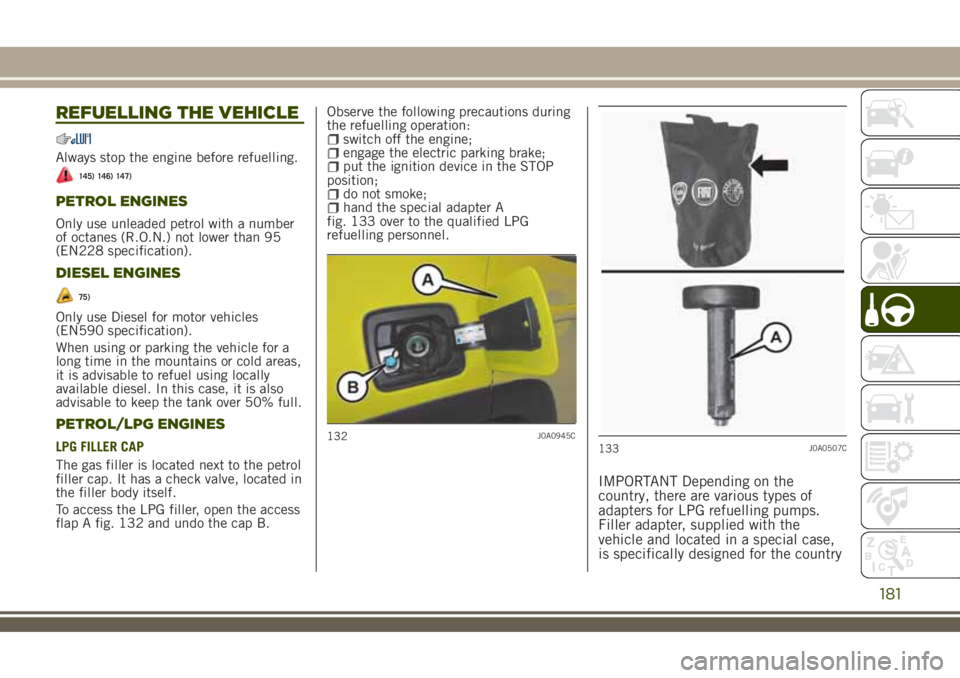
To access the LPG filler, open the access
flap A fig. 132 and undo the cap B.Observe the following precautions during
the refuelling operation:
switch off the engine;engage the electric parking brake;put the ignition device in the STOP
position;
do not smoke;hand the special adapter A
fig. 133 over to the qualified LPG
refuelling personnel.
IMPORTANT Depending on the
country, there are various types of
adapters for LPG refuelling pumps.
Filler adapter, supplied with the
vehicle and located in a special case,
is specifically designed for the country
132J0A0945C133J0A0507C
181
Page 191 of 356
Important
Apply the plate in a highly visible point
of the vehicle, near the mounting pipe or
inside the luggage compartment.
To ensure correct operation of the
system, periodically remove all deposits
of dirt which may have accumulated on
the ball head bar and from the mounting
pipe. The lock must only be treated with
graphite.
Periodically lubricate the joints, the
sliding surfaces and the balls with grease
without resin or oil. Lubrication is also a
further corrosion protection.
if the vehicle is washed with
high-pressure jets, the ball head bar
must be removed and the dedicated plug
fitted. The ball head bar must never be
treated with high-pressure jets.
Two keys are supplied together with the
removable ball tow bar. Note down the
four-digit key number and keep it in a
safe place. This number is to be used for
ordering any duplicate keys that may be
required.
IMPORTANT To install a tow hook
contact a Jeep Dealership.
WARNING
148)The ABS with which the car is
equipped will not control the braking
system of the trailer. Particular caution is
required on slippery roads.
149)Never modify the braking system of
the vehicle to control the trailer brake.
The trailer braking system must be fully
independent of the car’s hydraulic system.
189
Page 196 of 356
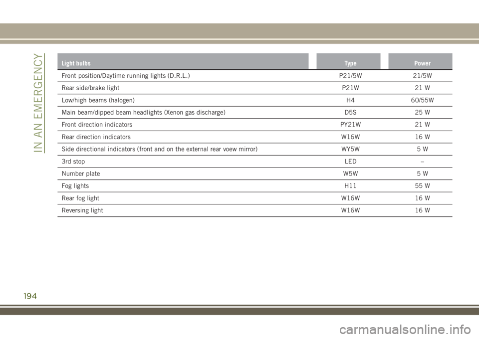
Light bulbsType Power
Front position/Daytime running lights (D.R.L.) P21/5W 21/5W
Rear side/brake lightP21W 21 W
Low/high beams (halogen)H4 60/55W
Main beam/dipped beam headlights (Xenon gas discharge) D5S 25 W
Front direction indicatorsPY21W 21 W
Rear direction indicatorsW16W 16 W
Side directional indicators (front and on the external rear voew mirror) WY5W 5 W
3rd stopLED –
Number plateW5W 5 W
Fog lightsH11 55 W
Rear fog lightW16W 16 W
Reversing lightW16W 16 W
194
IN AN EMERGENCY
Page 200 of 356
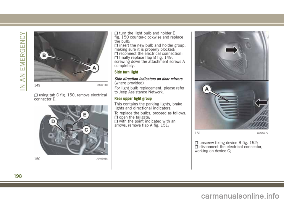
using tab C fig. 150, remove electrical
connector D;
turn the light bulb and holder E
fig. 150 counter-clockwise and replace
the bulb;
insert the new bulb and holder group,
making sure it is properly blocked;
reconnect the electrical connection;finally replace flap B fig. 149,
screwing down the attachment screws A
completely.
Side turn light
Side direction indicators on door mirrors
(where provided)
For light bulb replacement, please refer
to Jeep Assistance Network.
Rear upper light group
This contains the parking lights, brake
lights and directional indicators.
To replace the bulbs, proceed as follows:
open the tailgate;with the point indicated with an
arrows, remove flap A fig. 151;
unscrew fixing device B fig. 152;disconnect the electrical connector,
working on device C;
149J0A0211C
150J0A0301C
151J0A0637C
198
IN AN EMERGENCY
Page 201 of 356
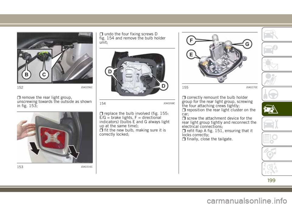
remove the rear light group,
unscrewing towards the outside as shown
in fig. 153;
undo the four fixing screws D
fig. 154 and remove the bulb holder
unit;
replace the bulb involved (fig. 155:
E/G = brake lights, F = directional
indicators) (bulbs E and G always light
up at the same time);
fit the new bulb, making sure it is
correctly locked;
correctly remount the bulb holder
group for the rear light group, screwing
the four attaching crews tightly;
reposition the rear light cluster on the
car;
screw the attachment device for the
rear light group tightly and reconnect the
electrical connections;
refit flap A fig. 151, ensuring that it
locks correctly;
finally, close the tailgate.
152J0A0296C
153J0A0316C
154J0A0268C
155J0A0270C
199
Page 202 of 356
Rear lower light cluster
These contain the rear fog light bulbs
(left side) and reversing light bulbs (right
side).
To replace the bulbs, proceed as follows:
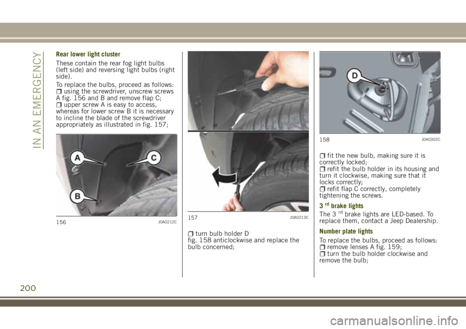
using the screwdriver, unscrew screws
A fig. 156 and B and remove flap C;
upper screw A is easy to access,
whereas for lower screw B it is necessary
to incline the blade of the screwdriver
appropriately as illustrated in fig. 157;
turn bulb holder D
fig. 158 anticlockwise and replace the
bulb concerned;
fit the new bulb, making sure it is
correctly locked;
refit the bulb holder in its housing and
turn it clockwise, making sure that it
locks correctly;
refit flap C correctly, completely
tightening the screws.
3
rdbrake lights
The 3rdbrake lights are LED-based. To
replace them, contact a Jeep Dealership.
Number plate lights
To replace the bulbs, proceed as follows:
remove lenses A fig. 159;turn the bulb holder clockwise and
remove the bulb;
156J0A0212C157J0A0213C
158J0A0302C
200
IN AN EMERGENCY
Page 212 of 356
CHANGING PROCEDURE
Proceed as follows:stop the car in a position that does
not cause any danger to traffic and lets
you change the tire in safety, as far as
possible from the edge of the driving
lane. The ground must be flat and
sufficiently compact;
engage the hazard warning lights and
the electric parking brake;
engage first gear or reverse or, for
versions with automatic transmission,
move the lever to position P (Park);
stop the engine and put on the
reflective safety jacket (for your own
safety and in compliance with national
laws) before getting out of the vehicle.
The motor must be kept off as long as
the car is lifted off the ground.
The spare tire, or depending on the
version, the temporary spare tire, are
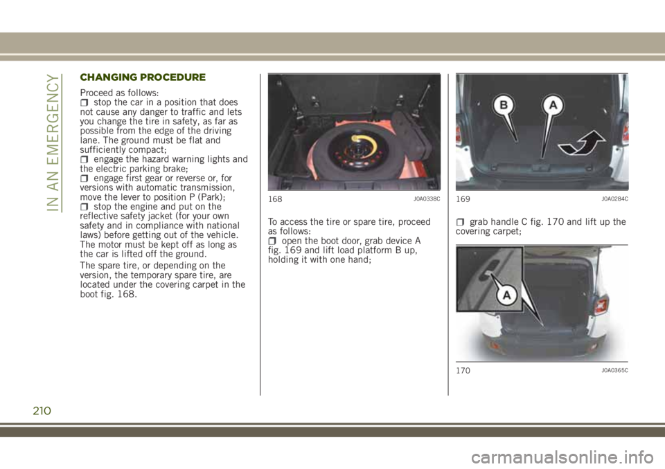
located under the covering carpet in the
boot fig. 168.To access the tire or spare tire, proceed
as follows:
open the boot door, grab device A
fig. 169 and lift load platform B up,
holding it with one hand;
grab handle C fig. 170 and lift up the
covering carpet;
168J0A0338C169J0A0284C
170J0A0365C
210
IN AN EMERGENCY
Page 217 of 356
TIREKIT
(where provided)
DESCRIPTION
168) 169)
79)
3)
The TireKit is located in the luggage
compartment inside its own box. The
container is also equipped with a
screwdriver, the tow ring and the
refuelling adaptor.
LPG versions
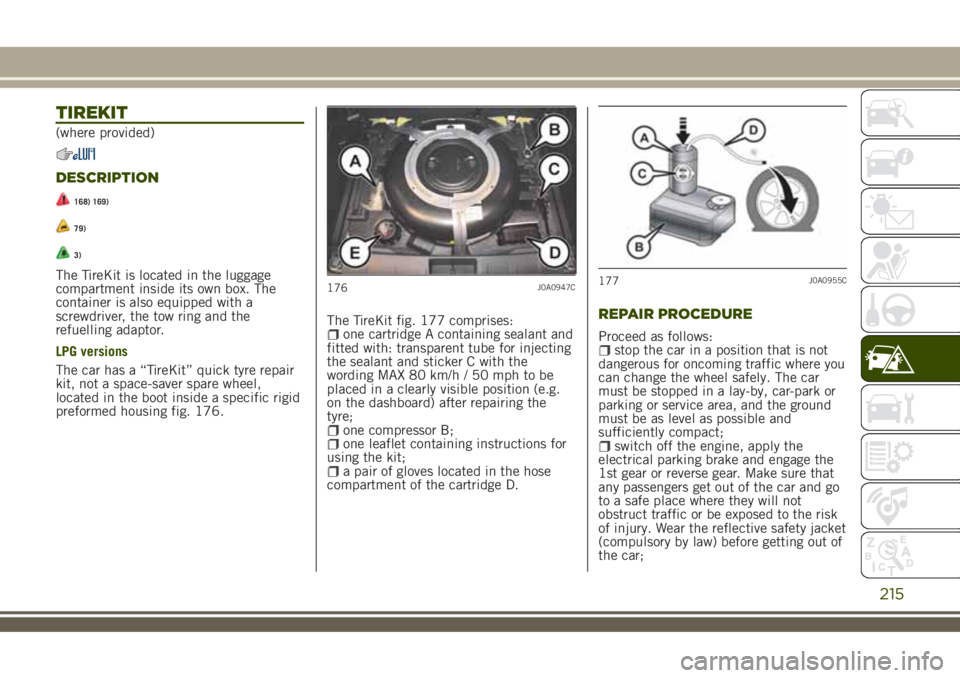
The car has a “TireKit” quick tyre repair
kit, not a space-saver spare wheel,
located in the boot inside a specific rigid
preformed housing fig. 176.The TireKit fig. 177 comprises:
one cartridge A containing sealant and
fitted with: transparent tube for injecting
the sealant and sticker C with the
wording MAX 80 km/h / 50 mph to be
placed in a clearly visible position (e.g.
on the dashboard) after repairing the
tyre;
one compressor B;one leaflet containing instructions for
using the kit;
a pair of gloves located in the hose
compartment of the cartridge D.
REPAIR PROCEDURE
Proceed as follows:stop the car in a position that is not
dangerous for oncoming traffic where you
can change the wheel safely. The car
must be stopped in a lay-by, car-park or
parking or service area, and the ground
must be as level as possible and
sufficiently compact;
switch off the engine, apply the
electrical parking brake and engage the
1st gear or reverse gear. Make sure that
any passengers get out of the car and go
to a safe place where they will not
obstruct traffic or be exposed to the risk
of injury. Wear the reflective safety jacket
(compulsory by law) before getting out of
the car;
176J0A0947C177J0A0955C
215
Page 218 of 356
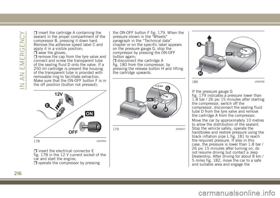
insert the cartridge A containing the
sealant in the proper compartment of the
compressor B, pressing it down hard.
Remove the adhesive speed label C and
apply it in a visible position;
wear the gloves;remove the cap from the tyre valve and
connect and screw the transparent tube
of the sealing fluid D onto the valve. If a
250 ml cartridge is present the housing
of the transparent tube is provided with
removable ring to facilitate extraction.
Make sure that the ON-OFF button F is in
the off position (button not pressed);
insert the electrical connector E
fig. 178 in the 12 V current socket of the
car and start the engine;
operate the compressor by pressingthe ON-OFF button F fig. 179. When the
pressure shown in the "Wheels"
paragraph in the “Technical data”
chapter or on the specific label appears
on the pressure gauge G, stop the
compressor by pressing the ON-OFF
button again;
disconnect the cartridge A
fig. 180 from the compressor, by
pressing the release button H and lifting
the cartridge upwards.
If the pressure gauge G
fig. 179 indicates a pressure lower than
1.8 bar / 26 psi 15 minutes after starting
the compressor, switch off the
compressor, disconnect the sealing fluid
tube D from the tyre valve and remove
the cartridge A from the compressor.
Move the car by approximately 10 metres
to allow the distribution of the sealant.
Stop the vehicle safely, operate the
handbrake and restore pressure using the
black inflation pipe L fig. 181 to reach
the required pressure. If also in this
case, the pressure is lower than 1.8 bar /
26 psi 15 minutes after turning on, do
not resume driving but contact a Jeep
Dealership. After driving for about 8 km /
5 miles fig. 182, move the car to a safe
and suitable area and engage the
ON
OFF 12V
E
178J0A0956
179J0A0957
A
H
180J0A0958
216
IN AN EMERGENCY
Page 219 of 356
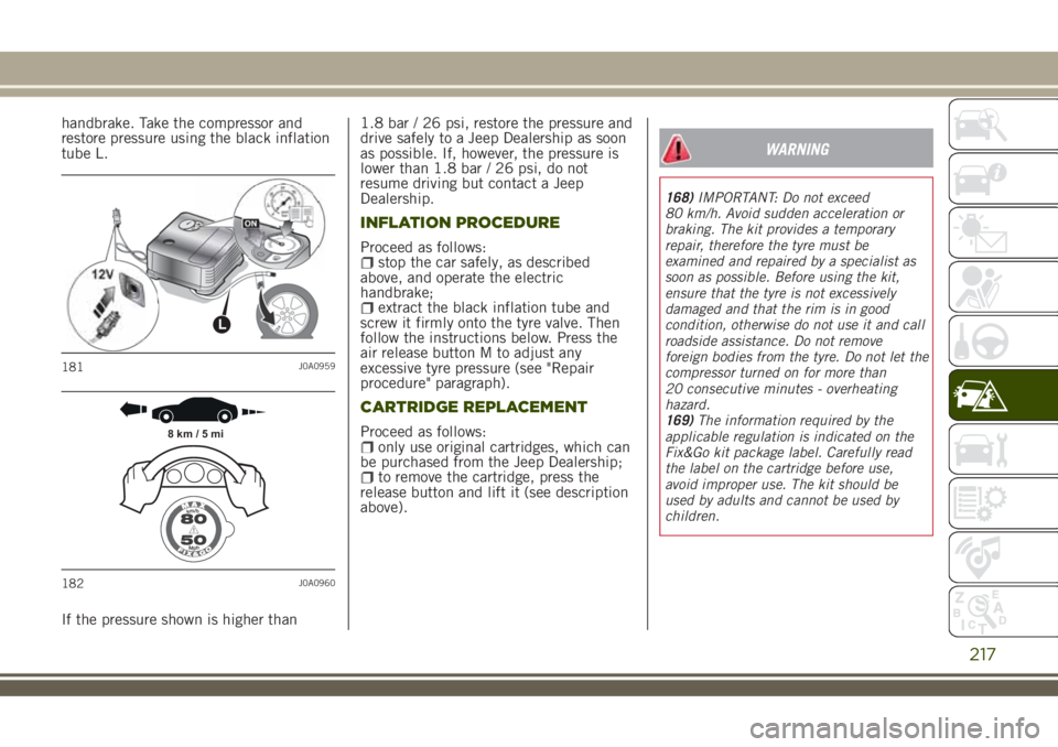
handbrake. Take the compressor and
restore pressure using the black inflation
tube L.
If the pressure shown is higher than1.8 bar / 26 psi, restore the pressure and
drive safely to a Jeep Dealership as soon
as possible. If, however, the pressure is
lower than 1.8 bar / 26 psi, do not
resume driving but contact a Jeep
Dealership.
INFLATION PROCEDURE
Proceed as follows:stop the car safely, as described
above, and operate the electric
handbrake;
extract the black inflation tube and
screw it firmly onto the tyre valve. Then
follow the instructions below. Press the
air release button M to adjust any
excessive tyre pressure (see "Repair
procedure" paragraph).
CARTRIDGE REPLACEMENT
Proceed as follows:only use original cartridges, which can
be purchased from the Jeep Dealership;
to remove the cartridge, press the
release button and lift it (see description
above).
WARNING
168)IMPORTANT: Do not exceed
80 km/h. Avoid sudden acceleration or
braking. The kit provides a temporary
repair, therefore the tyre must be
examined and repaired by a specialist as
soon as possible. Before using the kit,
ensure that the tyre is not excessively
damaged and that the rim is in good
condition, otherwise do not use it and call
roadside assistance. Do not remove
foreign bodies from the tyre. Do not let the
compressor turned on for more than
20 consecutive minutes - overheating
hazard.
169)The information required by the
applicable regulation is indicated on the
Fix&Go kit package label. Carefully read
the label on the cartridge before use,
avoid improper use. The kit should be
used by adults and cannot be used by
children.
L
181J0A0959
8 km / 5 mi
182J0A0960
217