check engine JEEP RENEGADE 2023 User Guide
[x] Cancel search | Manufacturer: JEEP, Model Year: 2023, Model line: RENEGADE, Model: JEEP RENEGADE 2023Pages: 364, PDF Size: 18.65 MB
Page 80 of 364
78 GETTING TO KNOW YOUR INSTRUMENT PANEL
ONBOARD DIAGNOSTIC SYSTEM
(OBD II) C
YBERSECURITY
Your vehicle is required to have an OBD II and a
connection port to allow access to information
related to the performance of your emissions
controls. Authorized service technicians may need
to access this information to assist with the
diagnosis and service of your vehicle and
emissions system Ú page 133.
EMISSIONS INSPECTION AND
MAINTENANCE PROGRAMS
In some localities, it may be a legal requirement to
pass an inspection of your vehicle's emissions
control system. Failure to pass could prevent
vehicle registration.
For states that require an Inspection and
Maintenance (I/M), this check verifies
the Ma
lfunction Indicator Light (MIL) is
functioning and is not on when the
engine is running, and that the OBD II system is
ready for testing.
Normally, the OBD II system will be ready. The
OBD II system may n
ot be r
eady if your vehicle was
recently serviced, recently had a depleted battery
or a battery replacement. If the OBD II system
should be determined not ready for the I/M test,
your vehicle may fail the test.
CAUTION!
Prolonged driving with the MIL on could cause
further damage to the emission control
system. It could also affect fuel economy and
driveability. The vehicle must be serviced
before any emissions tests can be performed.
If the MIL is flashing, while the engine is
running, severe catalytic converter damage
and power loss will soon occur. Immediate
service is required.
WARNING!
ONLY an authorized service technician should
connect equipment to the OBD II connection
port in order to read the VIN, diagnose, or
service your vehicle.
If unauthorized equipment is connected to the
OBD II connection port, such as a
driver-behavior tracking device, it may:
Be possible that vehicle systems,
including safety related systems, could be
impaired or a loss of vehicle control could
occur that may result in an accident
involving serious injury or death.
Access, or allow others to access, infor -
mation stored in your vehicle systems,
inclu d
ing personal information.
Page 81 of 364

GETTING TO KNOW YOUR INSTRUMENT PANEL 79
Your vehicle has a simple ignition actuated test,
which you can use prior to going to the test station.
To check if your vehicle's OBD II system is ready,
you must do the following:
1. Cycle the ignition switch to the ON position,
but d
o not crank or start the engine.
NOTE:
If you crank or start the engine, you will have to
start
this test over.
2. As soon as you cycle the ignition switch to the ON pos
ition, you will see the Malfunction
Indicator Light (MIL) symbol come on as part of
a normal bulb check. 3. Approximately 15 seconds later, one of two
thing
s will happen:
The MIL will flash for about 10 seconds and
then return to being fully illuminated until
you turn OFF the ignition or start the engine.
This means that your vehicle's OBD II
system is not ready and you should not
proceed to the I/M station.
The MIL will not flash at all and will remain
fully illuminated until you place the ignition
in the off position or start the engine. This
means that your vehicle's OBD II system is
ready and you can proceed to the I/M
station. If your OBD II system is
not rea
dy, you should see
an authorized dealer or repair facility. If your
vehicle was recently serviced or had a battery
failure or replacement, you may need to do nothing
more than drive your vehicle as you normally would
in order for your OBD II system to update. A
recheck with the above test routine may then
indicate that the system is now ready.
Regardless of whether your vehicle's OBD II system
is re a
dy or not, if the MIL is illuminated during
normal vehicle operation you should have your
vehicle serviced before going to the I/M station.
The I/M station can fail your vehicle because the
MIL is on with the engine running.3
Page 89 of 364
STARTING AND OPERATING 87
(Continued)
(Continued)
GEAR RANGES
PARK (P)
This range supplements the Electric Park Brake
(
E P
B )
by locking the transmission. The engine can
be started in this range. Never attempt to use
PARK while the vehicle is in motion.
When parking on a hill, apply the EPB before
shifti
ng the transmission to PARK, otherwise the
load on the transmission locking mechanism may
make it difficult to move the gear selector out of
PARK. As an added precaution, turn the front
wheels toward the curb on a downhill grade and
away from the curb on an uphill grade.
When exiting the vehicle, always:
Apply the parking brake.
Shift the transmission into PARK.
Turn the ignition OFF.
Remove the key fob from the vehicle.
CAUTION!
After selecting any gear range, wait a moment to
allow the selected gear to engage before
accelerating. This is especially important when
the engine is cold.
WARNING!
Never use the PARK position as a substitute
for the parking brake. Always apply the
parking brake fully when exiting the vehicle to
guard against vehicle movement and possible
injury or damage.
Your vehicle could move and injure you and
others if it is not in PARK. Check by trying to
move the transmission gear selector out of
PARK with the brake pedal released. Make
sure the transmission is in PARK before
exiting the vehicle.
The transmission may not engage PARK if the
vehicle is moving. Always bring the vehicle to a
complete stop before shifting to PARK, and
verify that the transmission gear position indi -
cator solidly indicates PARK (P) without
b linki
ng. Ensure that the vehicle is completely
stopped, and the PARK position is properly
indicated, before exiting the vehicle.
It is dangerous to shift out of PARK or
NEUTRAL if the engine speed is higher than
idle speed. If your foot is not firmly pressing
the brake pedal, the vehicle could accelerate
quickly forward or in reverse. You could lose
control of the vehicle and hit someone or
something. Only shift into gear when the
engine is idling normally (or stopped) and your
foot is firmly pressing the brake pedal.
Unintended movement of a vehicle could
injure those in or near the vehicle. As with all
vehicles, you should never exit a vehicle while
the engine is running or the propulsion system
is active. Before exiting a vehicle, always come
to a complete stop, then apply the parking
brake, shift the transmission into PARK, and
turn the ignition OFF. When the ignition is in
the OFF position, the transmission is locked in
PARK, securing the vehicle against unwanted
movement.
When leaving the vehicle, always make sure
the ignition is in the OFF position, remove the
key fob from the vehicle, and lock the vehicle.
WARNING!
4
Page 96 of 364

94 STARTING AND OPERATING
POSSIBLE REASONS THE ENGINE DOES
N
OT AUTOSTOP
Prior to engine shut down, the system will check
many safety and comfort conditions to see if they
are fulfilled. Detailed information about the
operation of the Stop/Start system may be viewed
in the instrument cluster display Stop/Start
Screen. In the following situations the engine will
not stop:
Driver’s seat belt is not buckled.
Driver’s door is not closed.
Battery temperature is too warm or cold.
Battery charge is low.
The vehicle is on a steep grade.
Cabin heating or cooling is in process and an
acceptable cabin temperature has not been
achieved.
HVAC is set to full defrost mode at a high blower
speed.
HVAC is set to MAX A/C.
Engine has not reached normal operating
temperature.
The transmission is not in a forward gear.
Hood is open.
Vehicle is in 4WD LOW transfer case mode (if
equipped with 4WD).
Brake pedal is not pressed with sufficient pres -
sure with vehicle in DRIVE position.
Accelerator pedal input.
Engine temp is too high.
5 mph (8 km/h) threshold not achieved from
previou
s AUTOSTOP.
Steering angle is beyond threshold.
It may be possible for the vehicle to be driven
s e v
e r
a
l times without the Stop/Start system going
into a STOP/START READY state under more
extreme conditions of the items listed above.
TO START THE ENGINE WHILE IN
A
UTOSTOP MODE
While in a forward gear, the engine will start when
the brake pedal is released or the throttle pedal is
pressed. The transmission will automatically
re-engage upon engine restart.
Conditions That Will Cause The Engine To Start
Automat
ically While In Autostop Mode:
The transmission gear selector is moved out of
DRIVE except in the PARK and NEUTRAL posi
-
tion.
To maintain cabin temperature comfort.
HVAC is set to full defrost mode.
HVAC system temperature or fan speed is
manually adjusted.
Battery voltage drops too low.
Stop/Start OFF switch is pushed.
A Stop/Start system error occurs.
4WD system is put into 4WD LOW mode (if
equipped with 4WD).
A system fault is present.
Conditions That Force An Application Of The
E le
ct
r
ic Park Brake While In Autostop Mode:
The driver’s door is open and brake pedal
released.
The driver’s door is open and the driver’s seat
belt is unbuckled.
The engine hood has been opened.
A Stop/Start system error occurs.
If the Electric Park Brake is applied with the engine
of f,
t
h
e engine may require a manual restart and
the Electric Park Brake may require a manual
release (press brake pedal and push Electric Park
Brake switch) Ú page 64.
Page 97 of 364
STARTING AND OPERATING 95
TO MANUALLY TURN OFF THE STOP/
S
TART SYSTEM
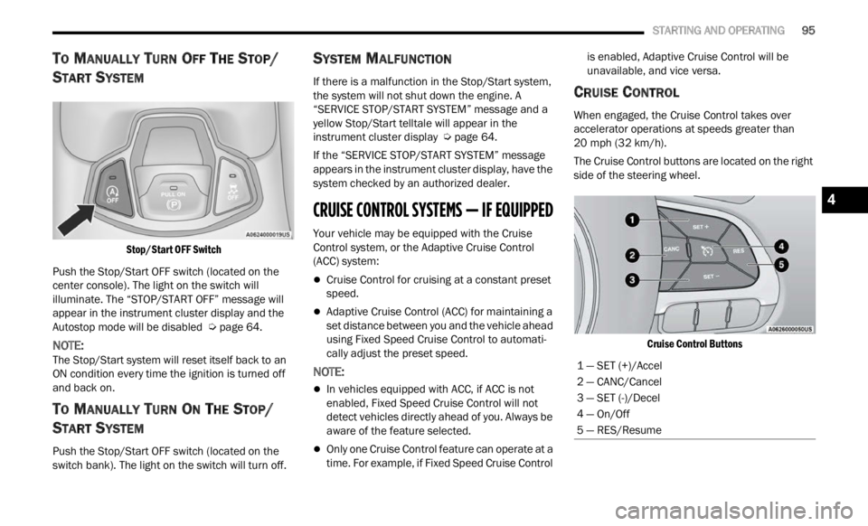
Stop/Start OFF Switch
Push the Stop/Start OFF switch (located on the
center
console). The light on the switch will
illuminate. The “STOP/START OFF” message will
appear in the instrument cluster display and the
Autostop mode will be disabled Ú page 64.
NOTE:
The Stop/Start system will reset itself back to an
ON con d
ition every time the ignition is turned off
and back on.
TO MANUALLY TURN ON THE STOP/
S
TART SYSTEM
Push the Stop/Start OFF switch (located on the
switch bank). The light on the switch will turn off.
SYSTEM MALFUNCTION
If there is a malfunction in the Stop/Start system,
the system will not shut down the engine. A
“SERVICE STOP/START SYSTEM” message and a
yellow Stop/Start telltale will appear in the
instrument cluster display Ú page 64.
If the “SERVICE STOP/START SYSTEM” message
appea r
s in the instrument cluster display, have the
system checked by an authorized dealer.
CRUISE CONTROL SYSTEMS — IF EQUIPPED
Your vehicle may be equipped with the Cruise
Control system, or the Adaptive Cruise Control
(ACC) system:
Cruise Control for cruising at a constant preset
speed.
Adaptive Cruise Control (ACC) for maintaining a
set distance between you and the vehicle ahead
using Fixed Speed Cruise Control to automati -
cally adjust the preset speed.
NOTE:
In vehicles equipped with ACC, if ACC is not
enabled, Fixed Speed Cruise Control will not
detect vehicles directly ahead of you. Always be
aware of the feature selected.
Only one Cruise Control feature can operate at a
time. For example, if Fixed Speed Cruise Control is enabled, Adaptive Cruise Control will be
unavailable, and vice versa.
CRUISE CONTROL
When engaged, the Cruise Control takes over
accelerator operations at speeds greater than
20
mph (32 km/h).
The Cruise Control buttons are located on the right
side of
the steering wheel.
Cruise Control Buttons
1 — SET (+)/Accel
2 — CANC/Cancel
3 — SET (-)/Decel
4 — On/Off
5 — RES/Resume
4
Page 129 of 364
STARTING AND OPERATING 127
(Continued)
(Continued)
Towing Requirements — Tires
Do not attempt to tow a trailer while using a
compact spare tire.
Proper tire inflation pressures are essential to
the safe and satisfactory operation of your
vehicle
Ú page 329.
Check the trailer tires for proper tire inflation
pressures before trailer usage.
Check for signs of tire wear or visible tire
damage before towing a trailer Ú page 329.
For the proper tire replacement procedures
Ú page 329. Replacing tires with a higher load
carrying capacity will not increase the vehicle's
G VWR a
nd GAWR limits.
Towing Requirements — Trailer Brakes
Do not interconnect the hydraulic brake system
or vacuum system of your vehicle with that of
the trailer. This could cause inadequate braking
and possible personal injury.
An electronically actuated trailer brake
controller is required when towing a trailer with
electronically actuated brakes. When towing a
trailer equipped with a hydraulic surge actuated
brake system, an electronic brake controller is
not required.
Trailer brakes are recommended for trailers
over 1,000 lb (453 kg) and required for trailers
in excess of 2,000 lb (907 kg).
When hauling cargo, or towing a trailer, do not
overload your vehicle or trailer. Overloading
can cause a loss of control, poor performance,
or damage to brakes, axle, engine, transmis -
sion, steering, suspension, chassis structure,
or tire
s.
Safety chains must always be used between
your vehicle and trailer. Always connect the
chains to the frame or hook retainers of the
vehicle hitch. Cross the chains under the
trailer tongue and allow enough slack for
turning corners.
Vehicles with trailers should not be parked on
a grade. When parking, apply the parking
brake on the tow vehicle. Put the tow vehicle
transmission in PARK. Always block or "chock"
the trailer wheels.
GCWR must not be exceeded.
Total weight must be distributed between the
tow vehicle and the trailer such that the
following four ratings are not exceeded:
GVWR
GTW
WARNING!
GAWR
Tongue weight rating for the trailer hitch
utilized.
CAUTION!
Do not tow a trailer at all during the first
500 miles (805 km) the new vehicle is driven.
The e n
gine, axle or other parts could be
damaged.
Then, during the first 500 miles (805 km) that
a trai
ler is towed, do not drive over 50 mph
( 8
0 k
m /
h) and do not make starts at full
thrott l
e. This helps the engine and other parts
of the vehicle wear in at the heavier loads.
WARNING!
WARNING!
Do not connect trailer brakes to your vehicle's
hydraulic brake lines. It can overload your
brake system and cause it to fail. You might
not have brakes when you need them and
could have a collision.
4
Page 211 of 364

MULTIMEDIA 209
Working Vehicle Conditions
The vehicle must in PARK or at a standstill.
The vehicle must be in an open area with cell
tower reception.
Your mobile device must have a cellular or Wi-Fi
connection.
Requirements
Vehicle must be properly equipped with
SiriusXM Guardian™.
Vehicle must have an operable LTE (voice/data)
or 3G or 4G (data) network connection. If using
the Mobile App to command your vehicle, your
device must be compatible and be connected to
an operable LTE (voice/data) or 3G or 4G (data)
network connection.
Vehicle must be registered with SiriusXM
Guardian™ and have an active subscription that
includes the applicable feature.
An ignition cycle is required for some remote
commands, such as Remote Vehicle Start and
Remote Door Lock/Unlock if following a Remote
Horn & Lights activation.
Your Remote Door Lock/Unlock request will not
be processed if the vehicle is in motion, the igni -
tion key is on or during an emergency call.
NOTE:
All other remote services should be performed via
your O w
ner’s Site or through the Mobile App on
your compatible device.
Remote Vehicle Start
Description
The Remote Vehicle Start feature provides you with
the a b
ility to start the engine on your vehicle
without the keys and from virtually any distance.
Once started, the preset climate controls in your
vehicle can warm up or cool down the interior.
You can also send a command to turn off an
engin e
that has been started using Remote Vehicle
Start. After 15 minutes, if you have not entered
your ve
hicle with the key, the engine will shut off
automatically.
This remote function requires your vehicle to be
equip p
ed with a factory-installed Remote Start
system.
You can set up push notifications every time a
comman d
is sent to activate or cancel Remote
Start. Working Vehicle Conditions
The vehicle must be off or in ACC mode.
The vehicle has been started with the key fob
within the last 14 days.
The vehicle must be in PARK or at a standstill.
The vehicle’s security system has been armed
and not triggered since the last vehicle start.
The doors, hood, and trunk/liftgate are closed.
The vehicle’s check engine light must be off.
The vehicle must have at least a quarter tank of
fuel, along with oil and battery power.
The vehicle’s hazard lights must be off.
If equipped, the vehicle must have an automatic
transmission.
The vehicle must be in an open area with cell
tower reception.
Your mobile device must have a cellular or Wi-Fi
connection.
If the Panic button has been pressed, the
vehicle must be started at least once after
alarming the system.
NOTE:
The SiriusXM Guardian™ Customer Care agents
are n ot
authorized for Remote Vehicle Start
services. Contact the Uconnect Care Team for
assistance.
5
Page 236 of 364

234 SAFETY
Service FCW Warning
If the system turns off, and the instrument cluster
display reads: “FCW Unavailable Service
Required”, this indicates there is an internal
system fault. Although the vehicle is still drivable
under normal conditions, have the system checked
by an authorized dealer.
“FCW Front Radar Sensor Temporarily Blocked”
Warni n
g
The “FCW Front Radar Sensor Temporarily
Blocked
” warning will display when conditions
temporarily limit system performance. This most
often occurs at times of poor visibility, such as in
snow or heavy rain. The system may also become
temporarily blinded due to obstructions, such as
mud, dirt or ice. In these cases, the instrument
cluster display will read “FCW Front Radar Sensor
Temporarily Blocked” and the system will
deactivate.
The “FCW Front Radar Sensor Temporarily
Blocke d
” message can sometimes be displayed
while driving in highly reflective areas (i.e. tunnels
with reflective tiles, or ice and snow). The system
will recover after the vehicle has left these areas.
Under rare conditions, when the radar is not
tracking any vehicles or objects in its path, this
warning may temporarily occur. If weather conditions are not a factor, the driver
shoul
d
examine the sensor. It may require cleaning
or removal of an obstruction. In absence of visible
obstructions on the fasica/bumper, it could be
necessary to wipe off the radar directly on the
surface, after having the radar cover removed. It’s
recommended that an authorized dealer perform
this operation.
NOTE:
If the “FCW Front Radar Sensor Temporarily
Blocked” message occurs frequently (e.g. more
than once on every trip) without any snow, rain,
mud, or other obstruction, have the radar
sensor realigned at an authorized dealer.
Installing a snow plow or front-end protector is
not recommended. Doing so may block the
sensor and inhibit FCW operation.
Use only a soft cloth for cleaning. Do not use
solvents or abrasive pastes.
The radar is equipped with a defrost system, so
in some climatic conditions it could reach high
temperatures. Wait at least 30 seconds after
the engine has been turned off before touching
the sensor.
Precautions While Driving With FCW
In certain driving conditions, such as:
Driving in the vicinity of a curve
Small vehicles and/or not aligned to the lane
Lane changing of other vehicles
Passing of vehicles in an oncoming intersection
The intervention of the system could be
u n e
xp
e
cted or delayed. The driver must therefore
always pay particular attention, while maintaining
control of the vehicle to drive in complete safety.
Driving In The Vicinity Of A Curve
Entering or exiting a large curve, the system could
detec t
the presence of a vehicle that is in front of
the vehicle, but that does not preside in the same
lane. In cases such as this, the system might
respond.
Driving In The Vicinity Of A Curve
Page 249 of 364
SAFETY 247
The ORC contains a backup power supply system
that may deploy the air bag system even if the
battery loses power or it becomes disconnected
prior to deployment.
The ORC turns on the Air Bag Warning Light in the
instru
ment panel for approximately four to eight
seconds for a self-check when the ignition switch is
in the MAR/ACC/ON/RUN position. After the
self-check, the Air Bag Warning Light will turn off. If
the ORC detects a malfunction in any part of the
system, it turns on the Air Bag Warning Light, either
momentarily or continuously. A single chime will
sound to alert you if the light comes on again after
initial startup.
The ORC also includes diagnostics that will
illum i
nate the instrument panel Air Bag Warning
Light if a malfunction is detected that could affect
the air bag system. The diagnostics also record the
nature of the malfunction. While the air bag system
is designed to be maintenance free, if any of the
following occurs, have an authorized dealer
service the air bag system immediately.
The Air Bag Warning Light does not come on
during the four to eight seconds when the igni -
tion switch is first in the MAR/ACC/ON/RUN
p osition
.
The Air Bag Warning Light remains on after the
four to eight-second interval.
The Air Bag Warning Light comes on intermit -
tently or remains on while driving.
NOTE:
If the speedometer, tachometer, or any engine
relat e
d gauges are not working, the Occupant
Restraint Controller (ORC) may also be disabled. In
this condition the air bags may not be ready to
inflate for your protection. Have an authorized
dealer service the air bag system immediately.
Redundant Air Bag Warning Light
If a fault with the Air Bag Warning Light is
detected, which could affect the
S up
p l
e
mental Restraint System (SRS),
the Redundant Air Bag Warning Light will
illuminate on the instrument panel. The
Redundant Air Bag Warning Light will stay on until
the fault is cleared. In addition, a single chime will
sound to alert you that the Redundant Air Bag
Warning Light has come on and a fault has been
detected. If the Redundant Air Bag Warning Light
comes on intermittently or remains on while driving have an authorized dealer service the vehicle
immediately
Ú page 69.
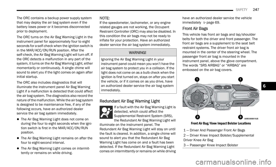
Front Air Bags
This vehicle has front air bags and lap/shoulder
belts for both the driver and front passenger. The
front air bags are a supplement to the seat belt
restraint systems. The driver front air bag is
mounted in the center of the steering wheel. The
passenger front air bag is mounted in the
instrument panel, above the glove compartment.
The words “SRS AIRBAG” or “AIRBAG” are
embossed on the air bag covers.
Front Air Bag/Knee Impact Bolster Locations
WARNING!
Ignoring the Air Bag Warning Light in your
instrument panel could mean you won’t have the
air bag system to protect you in a collision. If the
light does not come on as a bulb check when the
ignition is first turned on, stays on after you start
the vehicle, or if it comes on as you drive, have
an authorized dealer service the air bag system
immediately.
1 — Driver And Passenger Front Air Bags
2 — Driver Knee Impact Bolster/Supplemental
Driver Knee Air Bag
3 — Passenger Knee Impact Bolster
6
Page 255 of 364

SAFETY 253
NOTE:
After an accident, remember to cycle the ignition to
the S T
OP (OFF/LOCK) position and remove the key
from the ignition switch to avoid draining the
battery. Carefully check the vehicle for fuel leaks in
the engine compartment and on the ground near
the engine compartment and fuel tank before
resetting the system and starting the engine. If
there are no fuel leaks or damage to the vehicle
electrical devices (e.g. headlights) after an
accident, reset the system by following the procedure described below. If you have any doubt,
contact an authorized dealer.
Enhanced Accident Response System
Reset Procedure
After the event occurs, when the system is active,
a message regarding fuel cutoff is displayed. Turn
the ignition switch from ignition AVV/START or
MAR/ACC/ON/RUN to ignition STOP/OFF/LOCK.
Carefully check the vehicle for fuel leaks in the
engine compartment and on the ground near the
engine compartment and fuel tank before
resetting the system and starting the engine.
Depending on the nature of the event the left and
right
turn signal lights, located in the instrument
panel, may both be blinking and will continue to
blink. In order to move your vehicle to the side of
the road, you must follow the system reset
procedure.
Customer Action
NOTE:
Each step MUST BE held for at least two seconds.Customer Will See
1. Turn ignition STOP/OFF/LOCK. (Turn Signal Switch Must be placed in
Neutral State).
2. Turn ignition MAR/ACC/ON/RUN. Right turn light BLINKS.
Left turn light is OFF.
3. Turn right turn signal switch ON. Right turn light is ON SOLID.
Left turn light BLINKS.
4. Place turn signal in neutral state. Right turn light is OFF.
Left turn light BLINKS.
5. Turn left turn signal switch ON. Right turn light BLINKS.
Left turn light is ON SOLID.
6. Place turn signal in neutral state. Right turn light BLINKS.
Left turn light is OFF.6