check engine JEEP RENEGADE 2023 Owners Manual
[x] Cancel search | Manufacturer: JEEP, Model Year: 2023, Model line: RENEGADE, Model: JEEP RENEGADE 2023Pages: 364, PDF Size: 18.65 MB
Page 8 of 364
6
REFUELING IN EMERGENCY – IF EQUIPPED .. 280
IF YOUR ENGINE OVERHEATS ...... ...................... 281
GEAR SELECTOR OVERRIDE ...... ....................... 281
FREEING A STUCK VEHICLE ...... ........................ 282
TOWING A DISABLED VEHICLE ...... ...................283
Front–Wheel Drive (FWD) ...... ....................... 284
Four–Wheel Drive (4WD) ..... . ........................ 284
Emergency Tow Hooks — If Equipped . ..
..
. .... 284
ENHANCED ACCIDENT RESPONSE SYSTEM
(EARS) .................................................................. 285
EVEN T
DATA RECORDER (EDR) ...... ...................285
SERVICING AND MAINTENANCE
SCHEDULED SERVICING .................................... 286
Maintenance Plan ...... ................................... 287
ENGINE COMPARTMENT ..... . .............................. 293
1.3L Turbo Engine ...... ................................... 293
Checking Oil Level ..... . ................................... 294
Adding Washer Fluid . ..
..
. ............................... 294
Maintenance-Free Battery ..... . ..................... 294
Pressure Washing . ..
..
. ................................... 295
VEHICLE MAINTENANCE ..... . .............................. 295
Engine Oil ...................................................... 295
Engin e Oil Filter . ..
..
. ....................................... 296
Engine Air Cleaner Filter ..... . ........................ 296
Air Conditioner Maintenance . ..
..
. .................. 296Body Lubrication .....
.
..................................... 297
Windshield Wiper Blades ..... . ....................... 297
Exhaust System ..... . ...................................... 298
Cooling System . ..
..
. ........................................ 299
Brake System ..... . .......................................... 302
Automatic Transmission . ..
..
. ........................ 303
Fuses.............................................................. 303
Bulb
Replacement. ..
..
. ................................... 311
TIRES..................................................................... 322
Tire
Safety Information ...... ........................... 322
Tires — General Information . ..
..
. .................. 329
Tire Types....................................................... 332
Spar e
Tires — If Equipped . ..
. .
. ....................... 333
Wheel And Wheel Trim Care ..... . ................... 334
Snow Traction Devices . ..
..
. ........................... 335
Tire Rotation Recommendations ..... . .......... 336
DEPARTMENT OF TRANSPORTATION
UNIFORM TIRE QUALITY GRADES ..... .
............. 337
Treadwear ...................................................... 337
Tract ion Grades . ..
..
. ....................................... 337
Temperature Grades ..... . ............................... 337
STORING THE VEHICLE . ..
..
. ................................. 338
BODYWORK ...... ................................................... 338
Protection From Atmospheric Agents ...... .... 338
Body And Underbody Maintenance. ..
..
. ........ 338
Preserving The Bodywork ..... . ....................... 338INTERIORS .....
.
..................................................... 339
Seats And Fabric Parts ...... ........................... 339
Plastic And Coated Parts ..... . ........................ 339
Leather Surfaces. ..
..
. ..................................... 340
Glass Surfaces ..... . ....................................... 340
TECHNICAL SPECIFICATIONS
VEHICLE IDENTIFICATION NUMBER (VIN) ........ 341
BRAKE SYSTEM ...... ............................................. 341
WHEEL AND TIRE TORQUE SPECIFICATIONS .. 341 Tor que Specifications ...... ............................. 341
FUEL REQUIREMENTS . ..
..
. ................................... 342
1.3L Turbo Engine ...... ................................... 342
Reformulated Gasoline..... . ........................... 342
Gasoline/Oxygenate Blends . ..
..
. .................. 342
E-85 Usage In Non-Flex Fuel Vehicles ..... . ... 343
CNG And LP Fuel System Modifications . ..
..
. 343
Methylcyclopentadienyl Manganese
Tricarbonyl (MMT) In Gasoline . .....
............... 343
Materials Added To Fuel ..... . ......................... 343
Fuel System Cautions ..... . ............................. 344
FLUID CAPACITIES . ..
..
. ......................................... 344
ENGINE FLUIDS AND LUBRICANTS ...... ............ 345
CHASSIS FLUIDS AND LUBRICANTS ...... .......... 345
Page 13 of 364
11
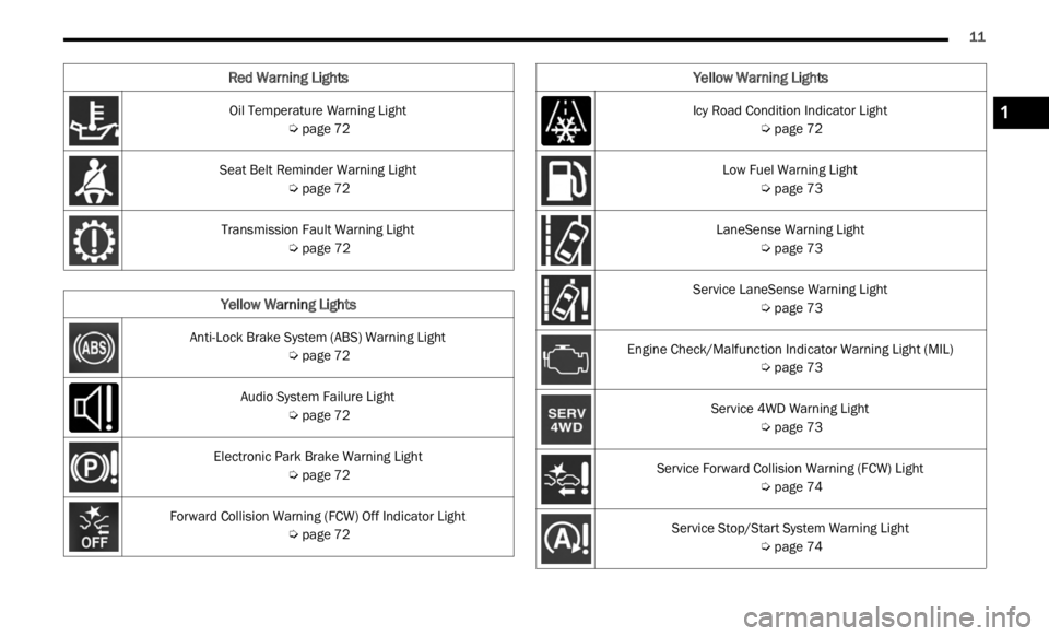
Oil Temperature Warning Light
Ú page 72
Seat Belt Reminder Warning Light Ú page 72
Transmission Fault Warning Light Ú page 72
Yellow Warning Lights
Anti-Lock Brake System (ABS) Warning Light
Ú page 72
Audio System Failure Light Ú page 72
Electronic Park Brake Warning Light Ú page 72
Forward Collision Warning (FCW) Off Indicator Light Ú page 72
Red Warning Lights
Icy Road Condition Indicator Light
Ú page 72
Low Fuel Warning Light Ú page 73
LaneSense Warning Light Ú page 73
Service LaneSense Warning Light Ú page 73
Engine Check/Malfunction Indicator Warning Light (MIL) Ú page 73
Service 4WD Warning Light Ú page 73
Service Forward Collision Warning (FCW) Light Ú page 74
Service Stop/Start System Warning Light Ú page 74
Yellow Warning Lights
1
Page 17 of 364
GETTING TO KNOW YOUR VEHICLE 15
Key Left Vehicle Feature — If Equipped
If a valid key fob is no longer detected inside the
vehicle while the vehicle’s ignition system is in the
ON/RUN or START position, the message “Key Fob
Has Left Vehicle” will be shown in the instrument
cluster display along with an interior chime. An
exterior audible and visual alert will also be
activated to warn the driver.
The vehicle’s horn will rapidly chirp three times
along
with a single flash of the vehicle’s exterior
lights.
NOTE:
The doors have to be open and then closed in
order for the vehicle to check for the presence of
a key fob; the Key Left Vehicle feature will not
activate until all of the doors are closed.
These alerts will not be activated in situations
where the vehicle’s engine is left running with
the key fob inside.
Replacing The Battery In The Key Fob
The replacement battery is one CR2032 battery.
NOTE:
Customers are recommended to use a battery
obtained from Mopar®. Aftermarket coin
battery dimensions may not meet the original
OEM coin battery dimensions.
Perchlorate Material — special handling may
apply. See www.dtsc.ca.gov/hazardouswaste/
perchlorate for further information.
Do not touch the battery terminals that are on
the back housing or the printed circuit board.
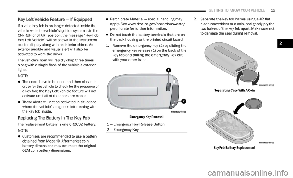
1. Remove the emergency key (2) by sliding the emerge
ncy key release (1) on the back of the
key fob and pulling the emergency key out
with your other hand.
Emergency Key Removal
2. Separate the key fob halves using a #2 flat
blad e
screwdriver or a coin, and gently pry the
two halves of the key fob apart. Make sure not
to damage the seal during removal.
Separating Case With A Coin
Key Fob Battery Replacement
1 — Emergency Key Release Button
2 — Emergency Key
2
Page 18 of 364
16 GETTING TO KNOW YOUR VEHICLE
3. Remove the back cover to access and replace
the battery. When replacing the battery, match
the (+) sign on the battery to the (+) sign on the
inside of the battery clip, located on the back
cover. Avoid touching the new battery with your
fingers. Skin oils may cause battery deterio -
ration. If you touch a battery, clean it with
r ubbi n
g alcohol.
4. To assemble the key fob case, snap the two halve
s together.
Programming And Requesting Additional
Key Fobs
Programming the key fob may be performed by an
authorized dealer.
NOTE:
Once a key fob is programmed to a vehicle, it
cannot be repurposed and reprogrammed to
another vehicle.
Only key fobs that are programmed to the
vehicle electronics can be used to start and
operate the vehicle. Once a key fob is
programmed to a vehicle, it cannot be
programmed to any other vehicle.
Duplication of key fobs may be performed at an
author i
zed dealer. This procedure consists of
programming a blank key fob to the vehicle
electronics. A blank key fob is one that has never
been programmed.
NOTE:
When having the Sentry Key Immobilizer system
serviced, bring all vehicle keys with you to an
authorized dealer.
Keys must be ordered to the correct key cut to
match the vehicle locks.
SENTRY KEY
The Sentry Key Immobilizer system prevents
unauthorized vehicle operation by disabling the
engine. The system does not need to be armed or
activated. Operation is automatic, regardless of
whether the vehicle is locked or unlocked.
The system uses a key fob, keyless push button
ignit i
on and a Radio Frequency (RF) receiver to
prevent unauthorized vehicle operation. Therefore,
only key fobs that are programmed to the vehicle
can be used to start and operate the vehicle. The
system will shut the engine off in two seconds if an
incorrect key fob is used to start the engine.
After placing the ignition switch in the ON/RUN
positi on
, the Vehicle Security Light will turn on for
three seconds for a bulb check. If the light remains
on after the bulb check, it indicates that there is a
problem with the electronics. In addition, if the light
begins to flash after the bulb check, it indicates
that someone used an invalid key fob to start the
engine. Either of these conditions will result in the
engine being shut off after two seconds.
WARNING!
The integrated key fob contains a coin cell
battery. Do not ingest the battery; there is a
chemical burn hazard. If the coin cell battery is
swallowed, it can cause severe internal burns
in just two hours and can lead to death.
If you think a battery may have been swal-
lowed or placed inside any part of the body,
seek i
mmediate medical attention.
Keep new and used batteries away from chil -
dren. If the battery compartment does not
close s
ecurely, stop using the product and
keep it away from children.
WARNING!
Always remove the key fobs from the vehicle
and lock all doors when leaving the vehicle
unattended.
For vehicles equipped with Keyless Enter ‘n
Go™ Ignition, always remember to place the
ignition in the OFF position.
Page 53 of 364
GETTING TO KNOW YOUR VEHICLE 51
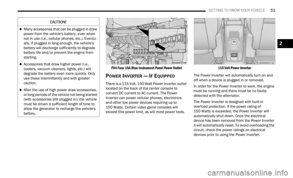
F94 Fuse 15A Blue Instrument Panel Power Outlet
POWER INVERTER — IF EQUIPPED
There is a 115 Volt, 150 Watt Power Inverter outlet
located on the back of the center console to
convert DC current to AC current. The Power
Inverter can power cellular phones, electronics
and other low power devices requiring up to
150 Watts. Certain video game consoles will
excee d
this power limit, as will most power tools.
115 Volt Power Inverter
The Power Inverter will automatically turn on and
off wh e
n a device is plugged in or removed.
In order for the Power Inverter to work, the engine
must b
e running and there must be no faults
detected with the alternator.
The Power Inverter is designed with built-in
overloa d
protection. If the power rating of
150 Watts is exceeded, the Power Inverter will
a utomat
ically shut down. Once the electrical
device has been removed from the Power Inverter
it will automatically reset. To avoid overloading the
circuit, check the power ratings on electrical
devices prior to using the Power Inverter.
CAUTION!
Many accessories that can be plugged in draw
power from the vehicle's battery, even when
not in use (i.e., cellular phones, etc.). Eventu -
ally, if plugged in long enough, the vehicle's
batte r
y will discharge sufficiently to degrade
battery life and/or prevent the engine from
starting.
Accessories that draw higher power (i.e.,
coolers, vacuum cleaners, lights, etc.) will
degrade the battery even more quickly. Only
use these intermittently and with greater
caution.
After the use of high power draw accessories,
or long periods of the vehicle not being started
(with accessories still plugged in), the vehicle
must be driven a sufficient length of time to
allow the generator to recharge the vehicle's
battery.
2
Page 71 of 364

GETTING TO KNOW YOUR INSTRUMENT PANEL 69
Sound Horn With Lock: activate/deactivate the
horn when pushing the LOCK button on the key
fob. The options are “Off,” “First Press,” and
“Second Press”
Horn With Remote Start: activate/deactivate
the horn at the Remote Starting of the engine
with the key fob
Remote Door Unlock: allows you to open the
driver door only on the first push of the UNLOCK
button on the key fob
“Compass”
By selecting the item “Compass” you can make the
f ollowi
ng adjustments:
Compass Calibration
Compass Variance
TRIP COMPUTER
The Trip computer is used to display information on
car operation when the key is turned to the RUN
position.
This function allows you to define two separate
trips
called “Trip A” and “Trip B” where the car's
“complete trips” are monitored in an independent
manner.
Both trips can be reset (reset - start of a new trip).
To perf
orm a reset, push and hold the OK button on
the steering wheel controls. “Trip A” and “Trip B” are used to display the figures
relat
i
ng to:
Distance Traveled
Average Consumption
Travel Time (driving time)
Quantities Displayed
Distance Traveled
Indicates the distance traveled by the start of
the new trip.
Average Consumption
Represents the average fuel consumption since
the start of the new trip.
Travel Time
Elapsed time since the start of the new trip.
OK Button
Short Push Of The Button: display of various
p arame
ters.
Long Push Of The Button: reset quantities and
begin
a new trip.
New trip
Starts after reset:
“Manual” by pushing the OK button.
“Automatic” when the “distance” reaches the
value of 62140 (99999.9 km) or when the “time
travel” reaches the value of 999.59
(999 hours and 59 minutes).
After each disconnection and reconnection of
the battery.
WARNING/INDICATOR LIGHTS AND
MESSAGES
The warning/indicator light switches on in the
instrument panel together with a dedicated
message and/or acoustic signal when applicable.
These indications are indicative and precautionary
and as such must not be considered as exhaustive
and/or alternative to the information contained in
the Owner Manual, which you are advised to read
carefully in all cases. Always refer to the
information in this chapter in the event of a failure
indication.
All active telltales will display first, if applicable.
The sy
stem check menu may appear different
based upon equipment options and current vehicle
status. Some telltales are optional and may not
appear.
The following warning lamps and indicators will
alert
you to a vehicle condition that may become
serious. Some lamps will illuminate when you start
your vehicle to make sure they work. If any lamps
remain on after starting your vehicle, refer to the
respective system warning lamp for further
information.
3
Page 72 of 364
70 GETTING TO KNOW YOUR INSTRUMENT PANEL
RED WARNING LIGHTS
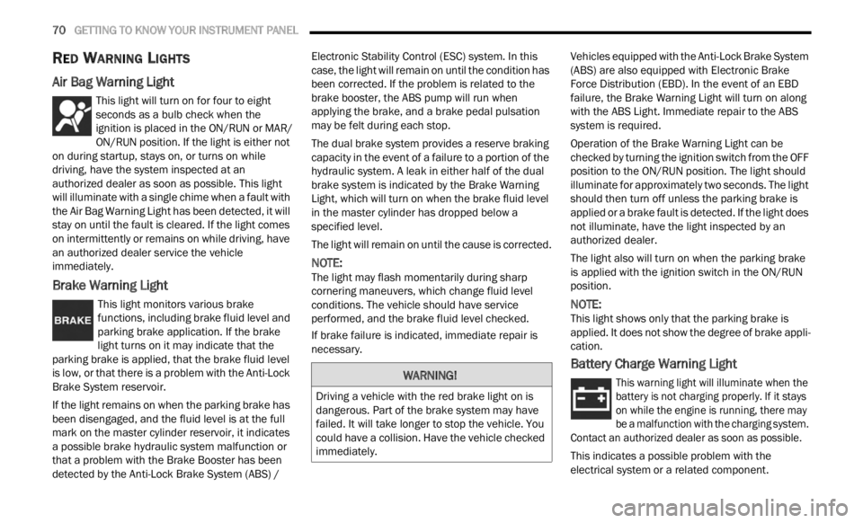
Air Bag Warning Light
This light will turn on for four to eight
seconds as a bulb check when the
i
g n
it
i
on is placed in the ON/RUN or MAR/
ON/RUN position. If the light is either not
on during startup, stays on, or turns on while
driving, have the system inspected at an
authorized dealer as soon as possible. This light
will illuminate with a single chime when a fault with
the Air Bag Warning Light has been detected, it will
stay on until the fault is cleared. If the light comes
on intermittently or remains on while driving, have
an authorized dealer service the vehicle
immediately.
Brake Warning Light
This light monitors various brake
functions, including brake fluid level and
parki n
g brake application. If the brake
light turns on it may indicate that the
parking brake is applied, that the brake fluid level
is low, or that there is a problem with the Anti-Lock
Brake System reservoir.
If the light remains on when the parking brake has
been d
isengaged, and the fluid level is at the full
mark on the master cylinder reservoir, it indicates
a possible brake hydraulic system malfunction or
that a problem with the Brake Booster has been
detected by the Anti-Lock Brake System (ABS) / Electronic Stability Control (ESC) system. In this
case, the light will remain on until the condition has
been corrected. If the problem is related to the
brake booster, the ABS pump will run when
applying the brake, and a brake pedal pulsation
may be felt during each stop.
The dual brake system provides a reserve braking
capac
i
ty in the event of a failure to a portion of the
hydraulic system. A leak in either half of the dual
brake system is indicated by the Brake Warning
Light, which will turn on when the brake fluid level
in the master cylinder has dropped below a
specified level.
The light will remain on until the cause is corrected.
NOTE:
The light may flash momentarily during sharp
corner i
ng maneuvers, which change fluid level
conditions. The vehicle should have service
performed, and the brake fluid level checked.
If brake failure is indicated, immediate repair is
necess
ary. Vehicles equipped with the Anti-Lock Brake System
(ABS)
are also equipped with Electronic Brake
Force Distribution (EBD). In the event of an EBD
failure, the Brake Warning Light will turn on along
with the ABS Light. Immediate repair to the ABS
system is required.
Operation of the Brake Warning Light can be
check e
d by turning the ignition switch from the OFF
position to the ON/RUN position. The light should
illuminate for approximately two seconds. The light
should then turn off unless the parking brake is
applied or a brake fault is detected. If the light does
not illuminate, have the light inspected by an
authorized dealer.
The light also will turn on when the parking brake
is ap p
lied with the ignition switch in the ON/RUN
position.
NOTE:
This light shows only that the parking brake is
appli e
d. It does not show the degree of brake appli -
cation.
Battery Charge Warning Light
This warning light will illuminate when the
battery is not charging properly. If it stays
on wh i
le the engine is running, there may
be a malfunction with the charging system.
Contact an authorized dealer as soon as possible.
This indicates a possible problem with the
electr
ical system or a related component.
WARNING!
Driving a vehicle with the red brake light on is
dangerous. Part of the brake system may have
failed. It will take longer to stop the vehicle. You
could have a collision. Have the vehicle checked
immediately.
Page 73 of 364
GETTING TO KNOW YOUR INSTRUMENT PANEL 71
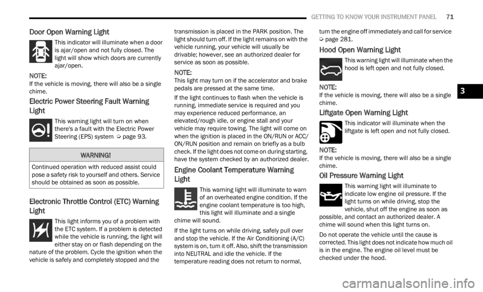
Door Open Warning Light
This indicator will illuminate when a door
is ajar/open and not fully closed. The
light
will show which doors are currently
ajar/open.
NOTE:
If the vehicle is moving, there will also be a single
chime .
Electric Power Steering Fault Warning
Light
This warning light will turn on when
there's a fault with the Electric Power
Steeri
ng (EPS) system Ú page 93.
Electronic Throttle Control (ETC) Warning
Light
This light informs you of a problem with
the ETC system. If a problem is detected
w
hi
l e
the vehicle is running, the light will
either stay on or flash depending on the
nature of the problem. Cycle the ignition when the
vehicle is safely and completely stopped and the transmission is placed in the PARK position. The
light should turn off. If the light remains on with the
vehicle running, your vehicle will usually be
drivable; however, see an authorized dealer for
service as soon as possible.
NOTE:
This light may turn on if the accelerator and brake
pedal s
are pressed at the same time.
If the light continues to flash when the vehicle is
runnin
g, immediate service is required and you
may experience reduced performance, an
elevated/rough idle, or engine stall and your
vehicle may require towing. The light will come on
when the ignition is placed in the ON/RUN or ACC/
ON/RUN position and remain on briefly as a bulb
check. If the light does not come on during starting,
have the system checked by an authorized dealer.
Engine Coolant Temperature Warning
Light
This warning light will illuminate to warn
of an overheated engine condition. If the
e n g
in
e
coolant temperature is too high,
this light will illuminate and a single
chime will sound.
If the light turns on while driving, safely pull over
and st
op the vehicle. If the Air Conditioning (A/C)
system is on, turn it off. Also, shift the transmission
into NEUTRAL and idle the vehicle. If the
temperature reading does not return to normal, turn the engine off immediately and call for service
Ú page 281.
Hood Open Warning Light
This warning light will illuminate when the
hood is left open and not fully closed.
NOTE:
If the vehicle is moving, there will also be a single
chime .
Liftgate Open Warning Light
This indicator will illuminate when the
liftgate is left open and not fully closed.
NOTE:
If the vehicle is moving, there will also be a single
chime .
Oil Pressure Warning Light
This warning light will illuminate to
indicate low engine oil pressure. If the
light
turns on while driving, stop the
vehicle, shut off the engine as soon as
possible, and contact an authorized dealer. A
chime will sound when this light turns on.
Do not operate the vehicle until the cause is
correc t
ed. This light does not indicate how much oil
is in the engine. The engine oil level must be
checked under the hood.
WARNING!
Continued operation with reduced assist could
pose a safety risk to yourself and others. Service
should be obtained as soon as possible.
3
Page 75 of 364
GETTING TO KNOW YOUR INSTRUMENT PANEL 73
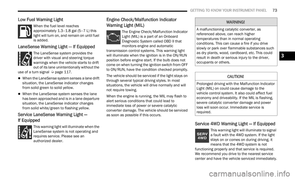
Low Fuel Warning Light
When the fuel level reaches
approximately 1.3–1.8 gal (5–7 L) this
light
will turn on, and remain on until fuel
is added.
LaneSense Warning Light — If Equipped
The LaneSense system provides the
driver with visual and steering torque
warni n
gs when the vehicle starts to drift
out of its lane unintentionally without the
use of a turn signal Ú page 117.
When the LaneSense system senses a lane drift
situation, the LaneSense indicator changes
from solid green to solid yellow.
When the LaneSense system senses the lane
has been approached and is in a lane departure
situation, the LaneSense indicator changes
from solid white/green to flashing yellow.
Service LaneSense Warning Light —
If Equipped
This warning light will illuminate when the
LaneSense system is not operating and
r e q
ui
r
es service. Please see an
authorized dealer.
Engine Check/Malfunction Indicator
Warning Light (MIL)
The Engine Check/Malfunction Indicator
Light (MIL) is a part of an Onboard
D ia
gn
os
tic System called OBD II that
monitors engine and automatic
transmission control systems. This warning light
will illuminate when the ignition is in the ON/RUN
position before engine start. If the bulb does not
come on when turning the ignition switch from OFF
to ON/RUN, have the condition checked promptly.
The vehicle should be serviced if the light stays on
throug h
several typical driving styles. In most
situations, the vehicle will drive normally and will
not require towing.
When the engine is running, the MIL may flash to
alert
serious conditions that could lead to
immediate loss of power or severe catalytic
converter damage. The vehicle should be serviced
as soon as possible if this occurs.
Service 4WD Warning Light — If Equipped
This warning light will illuminate to signal
a fault with the 4WD system. If the light
stays
on or comes on during driving, it
means that the 4WD system is not
functioning properly and that service is required.
We recommend you drive to the nearest service
center and have the vehicle serviced immediately.
WARNING!
A malfunctioning catalytic converter, as
referenced above, can reach higher
temperatures than in normal operating
conditions. This can cause a fire if you drive
slowly or park over flammable substances such
as dry plants, wood, cardboard, etc. This could
result in death or serious injury to the driver,
occupants or others.
CAUTION!
Prolonged driving with the Malfunction Indicator
Light (MIL) on could cause damage to the
vehicle control system. It also could affect fuel
economy and driveability. If the MIL is flashing,
severe catalytic converter damage and power
loss will soon occur. Immediate service is
required.
3
Page 77 of 364
GETTING TO KNOW YOUR INSTRUMENT PANEL 75
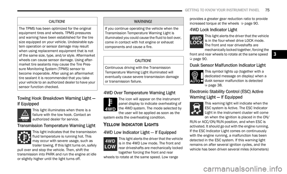
Towing Hook Breakdown Warning Light —
If Equipped
This light illuminates when there is a
failure with the tow hook. Contact an
a ut
h or
i
zed dealer for service.
Transmission Temperature Warning Light
This light indicates that the transmission
fluid temperature is running hot. This
may occ
ur with severe usage, such as
trailer towing. If this light turns on, safely
pull over and stop the vehicle. Then, shift the
transmission into PARK and run the engine at idle
or slightly higher until the light turns off.
4WD Over Temperature Warning Light
The icon will appear on the instrument
panel display to indicate overheating of
t h e
4
W
D system. The mode selected by
the user will be applied as soon as the
system exits the overheating condition.
YELLOW INDICATOR LIGHTS
4WD Low Indicator Light — If Equipped
This light alerts the driver that the vehicle
is in the 4WD Low mode. The front and
rear d
riveshafts are mechanically locked
together forcing the front and rear
wheels to rotate at the same speed. Low range provides a greater gear reduction ratio to provide
increased torque at the wheels
Ú page 90.
4WD Lock Indicator Light
This light alerts the driver that the vehicle
is in the four-wheel drive LOCK mode.
The f r
ont and rear driveshafts are
mechanically locked together, forcing the
front and rear wheels to rotate at the same speed
Ú page 90.
Dusk Sensor Malfunction Indicator Light
This symbol lights up (together with a
dedicated message on display) when a
dusk s
ensor malfunction is detected
Ú page 38.
Electronic Stability Control (ESC) Active
Warning Light — If Equipped
This warning light will indicate when the
ESC system is Active. The ESC Indicator
Light
in the instrument cluster will come
on when the ignition is placed in the ON/
RUN or ACC/ON/RUN position, and when ESC is
activated. It should go out with the engine running.
If the ESC Indicator Light comes on continuously
with the engine running, a malfunction has been
detected in the ESC system. If this warning light
remains on after several ignition cycles, and the
vehicle has been driven several miles (kilometers)
CAUTION!
The TPMS has been optimized for the original
equipment tires and wheels. TPMS pressures
and warning have been established for the tire
size equipped on your vehicle. Undesirable sys -
tem operation or sensor damage may result
w hen u
sing replacement equipment that is not
of the same size, type, and/or style. Aftermarket
wheels can cause sensor damage. Using after -
market tire sealants may cause the Tire Pres -
sure Monitoring System (TPMS) sensor to
b ecome
inoperable. After using an aftermarket
tire sealant it is recommended that you take
your vehicle to an authorized dealer to have your
sensor function checked.
WARNING!
If you continue operating the vehicle when the
Transmission Temperature Warning Light is
illuminated you could cause the fluid to boil over,
come in contact with hot engine or exhaust
components and cause a fire.
CAUTION!
Continuous driving with the Transmission
Temperature Warning Light illuminated will
eventually cause severe transmission damage
or transmission failure.
3