key JEEP RENEGADE 2023 Owner's Manual
[x] Cancel search | Manufacturer: JEEP, Model Year: 2023, Model line: RENEGADE, Model: JEEP RENEGADE 2023Pages: 364, PDF Size: 18.65 MB
Page 55 of 364
GETTING TO KNOW YOUR VEHICLE 53
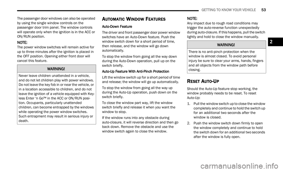
The passenger door windows can also be operated
by using the single window controls on the
passenger door trim panel. The window controls
will operate only when the ignition is in the ACC or
ON/RUN position.
NOTE:
The power window switches will remain active for
up to t
hree minutes after the ignition is placed in
the OFF position. Opening either front door will
cancel this feature.
AUTOMATIC WINDOW FEATURES
Auto-Down Feature
The driver and front passenger door power window
switc h
es have an Auto-Down feature. Push the
window switch down for a short period of time,
then release, and the window will go down
automatically.
To stop the window from going all the way down
durin g
the Auto-Down operation, pull up on the
switch briefly.
Auto-Up Feature With Anti-Pinch Protection
Lift the window switch up for a short period of time
a nd re
lease; the window will go up automatically.
To stop the window from going all the way up
during
the Auto-Up operation, push down on the
switch briefly.
To close the window part way, lift the window
switc h
briefly and release it when you want the
window to stop.
If the window runs into any obstacle during
auto-c l
osure, it will reverse direction and then go
back down. Remove the obstacle and use the
window switch again to close the window.
NOTE:
Any impact due to rough road conditions may
trigg e
r the auto-reverse function unexpectedly
during auto-closure. If this happens, pull the switch
lightly and hold to close the window manually.
RESET AUTO-UP
Should the Auto-Up feature stop working, the
window probably needs to be reset. To reset
Auto-Up:
1. Pull the window switch up to close the window comp l
etely and continue to hold the switch up
for an additional two seconds after the
window is closed.
2. Push the window switch down firmly to open the w
indow completely and continue to hold
the switch down for an additional two seconds
after the window is fully open.
WARNING!
Never leave children unattended in a vehicle,
and do not let children play with power windows.
Do not leave the key fob in or near the vehicle, or
in a location accessible to children, and do not
leave the ignition of a vehicle equipped with Key -
less Enter ‘n Go™ in the ACC or ON/RUN posi -
tion. Occupants, particularly unattended
c hildr
en, can become entrapped by the windows
while operating the power window switches.
Such entrapment may result in serious injury or
death.
WARNING!
There is no anti-pinch protection when the
window is almost closed. To avoid personal
injury be sure to clear your arms, hands, fingers
and all objects from the window path before
closing.
2
Page 56 of 364
54 GETTING TO KNOW YOUR VEHICLE
WINDOW LOCKOUT SWITCH
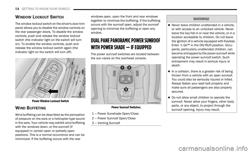
The window lockout switch on the driver's door trim
panel allows you to disable the window controls on
the rear passenger doors. To disable the window
controls, push and release the window lockout
switch (the indicator light on the switch will turn
on). To enable the window controls, push and
release the window lockout switch again (the
indicator light on the switch will turn off).
Power Window Lockout Switch
WIND BUFFETING
Wind buffeting can be described as the perception
of pressure on the ears or a helicopter-type sound
in the ears. Your vehicle may exhibit wind buffeting
with the windows down, or the sunroof (if
equipped) in certain open or partially open
positions. This is a normal occurrence and can be
minimized. If the buffeting occurs with the rear windows open, open the front and rear windows
together to minimize the buffeting. If the buffeting
occurs with the sunroof open, adjust the sunroof
opening to minimize the buffeting or open any
window.
DUAL PANE PANORAMIC POWER SUNROOF
WITH POWER SHADE — IF EQUIPPED
The power sunroof switches are located between
the sun visors on the overhead console.
Power Sunroof Switches
1 — Power Sunshade Open/Close
2 — Power Sunroof Open/Close
3 — Venting Sunroof
WARNING!
Never leave children unattended in a vehicle,
or with access to an unlocked vehicle. Never
leave the key fob in or near the vehicle, or in a
location accessible to children. Do not leave
the ignition of a vehicle equipped with Keyless
Enter ‘n Go™ in the ON/RUN position. Occu -
pants, particularly unattended children, can
b ecom e
entrapped by the power sunroof while
operating the power sunroof switch. Such
entrapment may result in serious injury or
death.
In a collision, there is a greater risk of being
thrown from a vehicle with an open sunroof.
You could also be seriously injured or killed.
Always fasten your seat belt properly and
make sure all passengers are also properly
secured.
Do not allow small children to operate the
sunroof. Never allow your fingers, other body
parts, or any object, to project through the
sunroof opening. Injury may result.
Page 57 of 364

GETTING TO KNOW YOUR VEHICLE 55
OPENING AND CLOSING THE SUNROOF
To retract the sunroof to the open position, push
the Open/Close switch and the sunroof will fully
open. The sunroof can be stopped in any position
by pushing/pulling the switch a second time while
opening.
To close the sunroof completely, pull the Open/
Close s
witch and the sunroof will fully close. The
sunroof can be stopped in any position by pushing/
pulling the switch a second time while it is closing.
VENTING SUNROOF
To vent the sunroof push the vent switch.
NOTE:
The vent switch has the automatic function only at
the op e
ning of the sunroof. During the closing of
the sunroof, the switch must be held until closed.
OPENING AND CLOSING THE POWER
S
UNSHADE
Express Open/Close
Push the shade switch for about one-half second
and t h
e shade will automatically open. During the
automatic open operation, any movement of the
shade switch will stop the shade. Pull the shade switch for about one-half second
and t
h
e shade will automatically close. During the
automatic close operation, any movement of the
shade switch will stop the shade.
Manual Open/Close
To open the shade part way, push the shade switch
brief l
y and release.
To close the shade part way, pull the shade switch
briefl
y and release.
NOTE:
The sunroof and the shade controls will operate
only when the ignition is in the ON/RUN posi -
tion.
If the Remote Start functionality is active, it is
not possible to move the sunroof.
PINCH PROTECT FEATURE
This feature will detect an obstruction in the
opening of the sunroof during Express Close
operation. If an obstruction in the path of the
sunroof is detected, the sunroof will automatically
retract. Remove the obstruction if this occurs.
WARNING!
Do not let children play with the sunroof.
Never leave children unattended in a vehicle,
or with access to an unlocked vehicle. Do not
leave the key fob in or near the vehicle, and do
not leave the ignition of a vehicle equipped
with Keyless Enter ‘n Go™ in the ACC or ON/
RUN position. Occupants, particularly unat -
tended children, can become entrapped by
the p ow
er sunroof while operating the power
sunroof switch. Such entrapment may result
in serious injury or death.
In a collision, there is a greater risk of being
thrown from a vehicle with an open sunroof.
You could also be severely injured or killed.
Always fasten your seat belt properly and
make sure all passengers are properly
secured.
Do not allow small children to operate the
sunroof. Never allow your fingers, other body
parts, or any object to project through the
sunroof opening. Injury may result.
2
Page 58 of 364
56 GETTING TO KNOW YOUR VEHICLE
SUNROOF MAINTENANCE
Use only a non-abrasive cleaner and a soft cloth to
clean the glass panel. Periodically check for and
clear out any debris that may have collected in the
tracks.
HOOD
TO OPEN THE HOOD
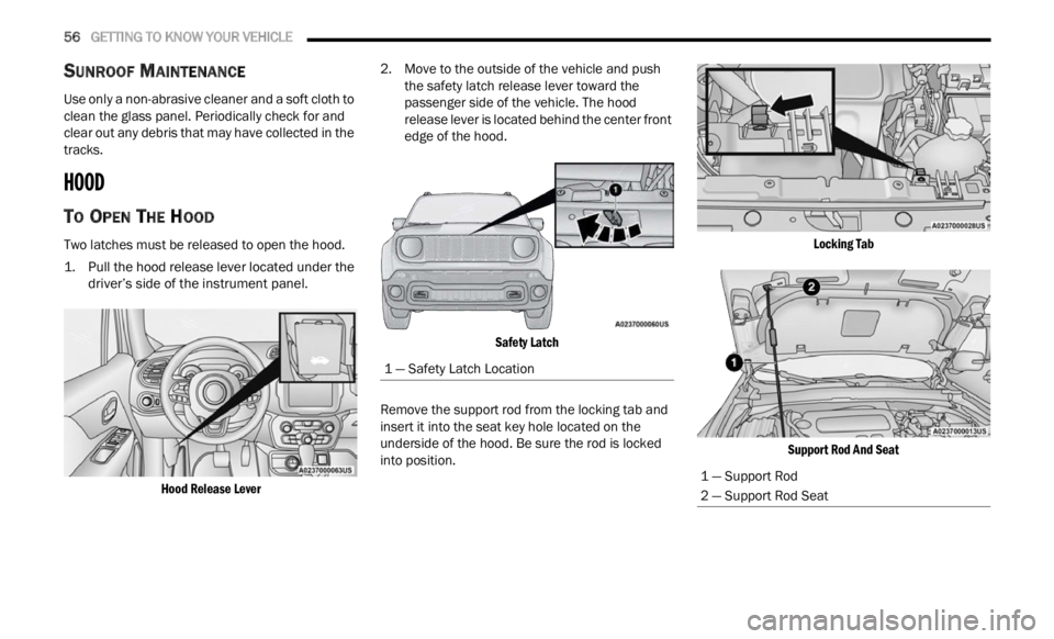
Two latches must be released to open the hood.
1. Pull the hood release lever located under the
driver’ s
side of the instrument panel.
Hood Release Lever
2. Move to the outside of the vehicle and push
the s
afety latch release lever toward the
passenger side of the vehicle. The hood
release lever is located behind the center front
edge of the hood.
Safety Latch
Remove the support rod from the locking tab and
inser t
it into the seat key hole located on the
underside of the hood. Be sure the rod is locked
into position.
Locking Tab
Support Rod And Seat
1 — Safety Latch Location
1 — Support Rod
2 — Support Rod Seat
Page 59 of 364
GETTING TO KNOW YOUR VEHICLE 57
TO CLOSE THE HOOD
LIFTGATE
UNLOCK/OPEN THE LIFTGATE
To unlock the liftgate, use the key fob or activate
the power door lock switches located on the driver
door handle.
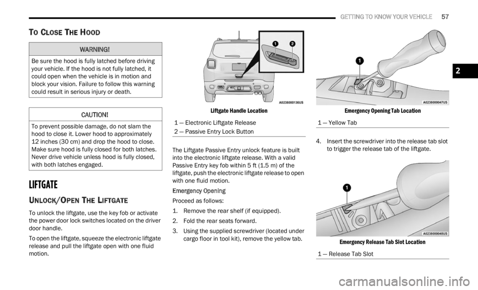
To open the liftgate, squeeze the electronic liftgate
relea s
e and pull the liftgate open with one fluid
motion.
Liftgate Handle Location
The Liftgate Passive Entry unlock feature is built
into t h
e electronic liftgate release. With a valid
Passive Entry key fob within 5 ft (1.5 m) of the
liftga
te, push the electronic liftgate release to open
with one fluid motion.
Emergency Opening
Proceed as follows:
1. R emove the rear shelf (if equipped).
2. Fol d
the rear seats forward.
3. Us i
ng the supplied screwdriver (located under
carg o
floor in tool kit), remove the yellow tab.
Emergency Opening Tab Location
4. Insert the screwdriver into the release tab slot to tri
gger the release tab of the liftgate.
Emergency Release Tab Slot Location
WARNING!
Be sure the hood is fully latched before driving
your vehicle. If the hood is not fully latched, it
could open when the vehicle is in motion and
block your vision. Failure to follow this warning
could result in serious injury or death.
CAUTION!
To prevent possible damage, do not slam the
hood to close it. Lower hood to approximately
12 inches (30 cm) and drop the hood to close.
Make s
ure hood is fully closed for both latches.
Never drive vehicle unless hood is fully closed,
with both latches engaged.
1 — Electronic Liftgate Release
2 — Passive Entry Lock Button
1 — Yellow Tab
1 — Release Tab Slot
2
Page 60 of 364
58 GETTING TO KNOW YOUR VEHICLE
LOCK/CLOSE THE LIFTGATE
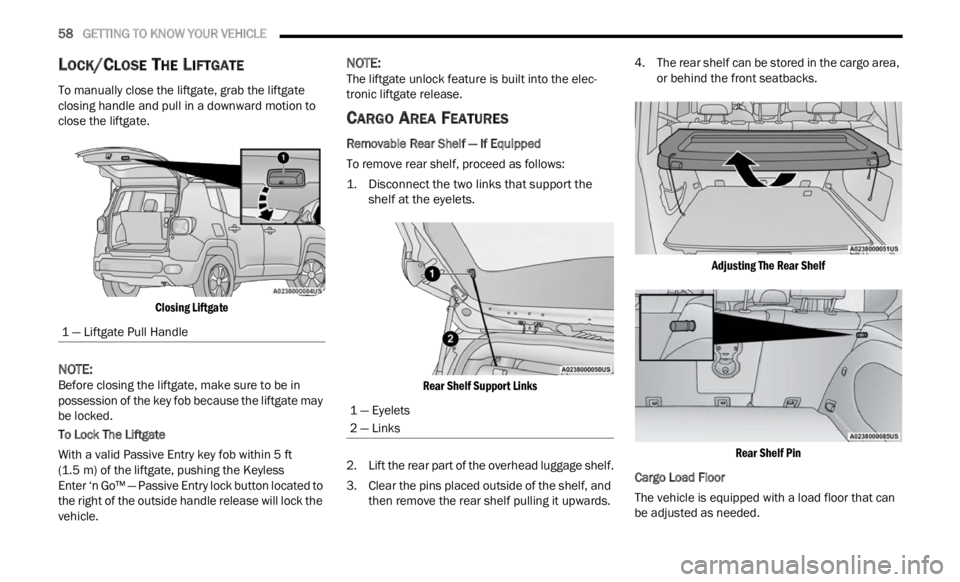
To manually close the liftgate, grab the liftgate
closing handle and pull in a downward motion to
close the liftgate.
Closing Liftgate
NOTE:
Before closing the liftgate, make sure to be in
posses s
ion of the key fob because the liftgate may
be locked.
To Lock The Liftgate
With a valid Passive Entry key fob within 5 ft
( 1.5 m)
of the liftgate, pushing the Keyless
Enter ‘n Go™ — Passive Entry lock button located to
t he ri
ght of the outside handle release will lock the
vehicle.
NOTE:
The liftgate unlock feature is built into the elec -
tronic liftgate release.
CARGO AREA FEATURES
Removable Rear Shelf — If Equipped
To remove rear shelf, proceed as follows:
1. D isconnect the two links that support the
shelf a
t the eyelets.
Rear Shelf Support Links
2. Li ft the rear part of the overhead luggage shelf.
3 . C
le
ar the pins placed outside of the shelf, and
then
remove the rear shelf pulling it upwards. 4. The rear shelf can be stored in the cargo area,
or be h
ind the front seatbacks.
Adjusting The Rear Shelf Rear Shelf Pin
Cargo Load Floor
The vehicle is equipped with a load floor that can
b e ad j
usted as needed.
1 — Liftgate Pull Handle
1 — Eyelets
2 — Links
Page 71 of 364

GETTING TO KNOW YOUR INSTRUMENT PANEL 69
Sound Horn With Lock: activate/deactivate the
horn when pushing the LOCK button on the key
fob. The options are “Off,” “First Press,” and
“Second Press”
Horn With Remote Start: activate/deactivate
the horn at the Remote Starting of the engine
with the key fob
Remote Door Unlock: allows you to open the
driver door only on the first push of the UNLOCK
button on the key fob
“Compass”
By selecting the item “Compass” you can make the
f ollowi
ng adjustments:
Compass Calibration
Compass Variance
TRIP COMPUTER
The Trip computer is used to display information on
car operation when the key is turned to the RUN
position.
This function allows you to define two separate
trips
called “Trip A” and “Trip B” where the car's
“complete trips” are monitored in an independent
manner.
Both trips can be reset (reset - start of a new trip).
To perf
orm a reset, push and hold the OK button on
the steering wheel controls. “Trip A” and “Trip B” are used to display the figures
relat
i
ng to:
Distance Traveled
Average Consumption
Travel Time (driving time)
Quantities Displayed
Distance Traveled
Indicates the distance traveled by the start of
the new trip.
Average Consumption
Represents the average fuel consumption since
the start of the new trip.
Travel Time
Elapsed time since the start of the new trip.
OK Button
Short Push Of The Button: display of various
p arame
ters.
Long Push Of The Button: reset quantities and
begin
a new trip.
New trip
Starts after reset:
“Manual” by pushing the OK button.
“Automatic” when the “distance” reaches the
value of 62140 (99999.9 km) or when the “time
travel” reaches the value of 999.59
(999 hours and 59 minutes).
After each disconnection and reconnection of
the battery.
WARNING/INDICATOR LIGHTS AND
MESSAGES
The warning/indicator light switches on in the
instrument panel together with a dedicated
message and/or acoustic signal when applicable.
These indications are indicative and precautionary
and as such must not be considered as exhaustive
and/or alternative to the information contained in
the Owner Manual, which you are advised to read
carefully in all cases. Always refer to the
information in this chapter in the event of a failure
indication.
All active telltales will display first, if applicable.
The sy
stem check menu may appear different
based upon equipment options and current vehicle
status. Some telltales are optional and may not
appear.
The following warning lamps and indicators will
alert
you to a vehicle condition that may become
serious. Some lamps will illuminate when you start
your vehicle to make sure they work. If any lamps
remain on after starting your vehicle, refer to the
respective system warning lamp for further
information.
3
Page 82 of 364
80
(Continued)
STARTING AND OPERATING
STARTING THE ENGINE
Before starting your vehicle, adjust your seat,
adjust the inside and outside mirrors, fasten your
seat belt, and if present, instruct all other
occupants to buckle their seat belts.
Start the engine with the gear selector in the
NEUTRA
L or PARK position. Apply the brake before
shifting to any driving range. Normal Starting
NOTE:
Normal starting of either a cold or warm engine is
obtain e
d without pumping or pressing the accel -
erator pedal.
Proceed as follows:
1. S et the Electric Park Brake (EPB) and put the
gear s
elector in the PARK or NEUTRAL
position.
2. Press on the brake pedal, without pressing the acce l
erator.
3. Press the START/STOP ignition button and relea
se it as soon as the engine is started.
4. If the engine does not start, place the ignition in th
e OFF position and wait 10-15 seconds
before attempting to restart the engine.
TIP START FEATURE
Do not press the accelerator. Press briefly the
START/STOP ignition button and release it. The
starter motor will continue to run but will
automatically disengage when the engine is
running.
IF ENGINE FAILS TO START
If the engine fails to start after you have followed
the “Normal Starting” procedure, and has not
experienced an extended park condition as
identified in “Extended Park Starting” procedure
below, it may be flooded. Push the accelerator
pedal all the way to the floor and hold it there.
Crank the engine for no more than 10 seconds.
This should clear any excess fuel in case the
engine is flooded. Leave the ignition in the RUN
position, release the accelerator pedal and repeat
the “Normal Starting” procedure.
WARNING!
Never leave children alone in a vehicle, or with
access to an unlocked vehicle.
Allowing children to be in a vehicle unattended
is dangerous for a number of reasons. A child
or others could be seriously or fatally injured.
Children should be warned not to touch the
parking brake, brake pedal or the gear
selector.
Do not leave the key fob in or near the vehicle
(or in a location accessible to children), and do
not leave the ignition in the ON or RUN posi -
tion. A child could operate power windows,
other c
ontrols, or move the vehicle.
WARNING!
Never pour fuel or other flammable liquid into
the throttle body air inlet opening in an attempt
to start the vehicle. This could result in flash fire
causing serious personal injury.
WARNING!
Never pour fuel or other flammable liquid into
the throttle body air inlet opening in an
attempt to start the vehicle. This could result
in flash fire causing serious personal injury.
Page 83 of 364

STARTING AND OPERATING 81
COLD WEATHER OPERATION
To ensure reliable starting under extreme cold
conditions an externally powered electric block
heater (if equipped) is required for the 1.3L Turbo
engine below -20°F (-29°C). To prevent possible engine damage while starting
at low
temperatures, this vehicle will inhibit engine
cranking when the ambient temperature is less
than -20°F (-29°C) for the 1.3L Turbo engine, and
the oil temperature sensor reading indicates an
engine block heater has not been used. The
message “plug in engine heater” will be displayed
in the instrument cluster when the ambient
temperature is below -4°F (-20°C) at the time the
engine is shut off as a reminder to avoid possible
crank delays at the next cold start.
EXTENDED PARK STARTING
NOTE:
Extended Park condition occurs when the vehicle
has n ot
been started or driven for at least 30 days.
1. Install a battery charger or jumper cables to the ba
ttery to ensure a full battery charge
during the crank cycle.
2. Press the START/STOP ignition button and relea
se it when the engine starts.
3. If the engine fails to start within 10 seconds, place
the ignition in the OFF position, wait
10 to 15 seconds to allow the starter to cool,
t hen r
epeat the Extended Park Starting
procedure.
4. If the engine fails to start after eight attempts, allow
the starter to cool for at least
10 minutes, then repeat the procedure.
AFTER STARTING — WARMING UP THE
E
NGINE
Proceed as follows:
Travel slowly, letting the engine run at a reduced
RPM, without accelerating suddenly.
It is recommended to wait until the engine
coolant temperature gauge starts to rise for
maximum performance.
STOPPING THE ENGINE
To shut off the engine with a vehicle speed greater
than 5 mph (8 km/h), you must push and hold the
ignit i
on or push the START/STOP button three
times consecutively within a few seconds. The
engine will shut down, and the ignition will be
placed in the RUN position.
Vehicles Equipped With Electronic Key
(Keyless Enter ‘n Go™)
Turning off the car (cycle the ignition from the RUN
p ositi on
to the OFF position), the power supply to
the accessories are maintained for a period of
three minutes.
Do not attempt to push or tow your vehicle to
get it started. Vehicles equipped with an auto -
matic transmission cannot be started this
w ay. U
nburned fuel could enter the catalytic
converter and once the engine has started,
ignite and damage the converter and vehicle.
If the vehicle has a discharged battery,
booster cables may be used to obtain a start
from a booster battery or the battery in
another vehicle. This type of start can be
dangerous if done improperly Ú page 278.
CAUTION!
To prevent damage to the starter, do not
continuously crank the engine for more than
10 seconds at a time. Wait 10 to 15 seconds
before
trying again.
WARNING!CAUTION!
To prevent damage to the starter, do not crank
continuously for more than 10 seconds at a
time. Wait 10 to 15 seconds before trying again.
4
Page 85 of 364
STARTING AND OPERATING 83
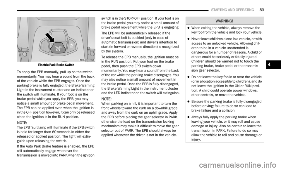
Electric Park Brake Switch
To apply the EPB manually, pull up on the switch
momenta
rily. You may hear a sound from the back
of the vehicle while the EPB engages. Once the
parking brake is fully engaged, the Brake Warning
Light in the instrument cluster and an indicator on
the switch will illuminate. If your foot is on the
brake pedal while you apply the EPB, you may
notice a small amount of brake pedal movement.
The EPB can be applied even when the ignition is
in the OFF position however, it can only be released
when the ignition is in the RUN position.
NOTE:
The EPB fault lamp will illuminate if the EPB switch
is he l
d for longer than 60 seconds in either the
released or applied position. The light will extin -
guish upon releasing the switch.
If the Auto Park Brake feature is enabled, the EPB
w ill a
utomatically engage whenever the
transmission is moved into PARK when the ignition switch is in the STOP/OFF position. If your foot is on
the brake pedal, you may notice a small amount of
brake pedal movement while the EPB is engaging.
The EPB will be automatically released if the
drive
r
's seat belt is buckled (only in case of
automatic transmission) and driver's intention to
start (in forward or reverse direction) is recognized
by the system.
To release the EPB manually, the ignition must be
in th e
RUN position. Put your foot on the brake
pedal, then push the EPB switch down
momentarily. You may hear a sound from the back
of the car while the parking brake disengages. You
may also notice a small amount of movement in
the brake pedal. Once the EPB is fully disengaged,
the Brake Warning Light in the instrument cluster
and the LED indicator on the switch will extinguish.
NOTE:
When parking on a hill, it is important to turn the
front w
heels toward the curb on a downhill grade
and away from the curb on an uphill grade. Apply
the EPB before placing the gear selector in PARK,
otherwise the load on the transmission locking
mechanism may make it difficult to move the gear
selector out of PARK. The EPB should always be
applied whenever the driver is not in the vehicle.
WARNING!
When exiting the vehicle, always remove the
key fob from the vehicle and lock your vehicle.
Never leave children alone in a vehicle, or with
access to an unlocked vehicle. Allowing chil -
dren to be in a vehicle unattended is
d anger
ous for a number of reasons. A child or
others could be seriously or fatally injured.
Children should be warned not to touch the
parking brake, brake pedal or the transmis -
sion gear selector.
Do not leave the key fob in or near the vehicle
(or in a location accessible to children), and do
not leave the ignition in the ON or RUN posi -
tion. A child could operate power windows,
other c
ontrols, or move the vehicle.
Be sure the parking brake is fully disengaged
before driving; failure to do so can lead to
brake failure and a collision.
Always fully apply the parking brake when
leaving your vehicle, or it may roll and cause
damage or injury. Also be certain to leave the
transmission in PARK. Failure to do so may
allow the vehicle to roll and cause damage or
injury.
4