warning JEEP RENEGADE 2023 Owner's Manual
[x] Cancel search | Manufacturer: JEEP, Model Year: 2023, Model line: RENEGADE, Model: JEEP RENEGADE 2023Pages: 364, PDF Size: 18.65 MB
Page 29 of 364
GETTING TO KNOW YOUR VEHICLE 27
MANUAL FRONT SEATS
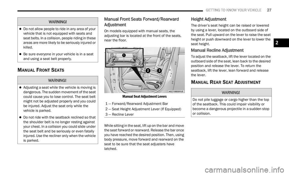
Manual Front Seats Forward/Rearward
Adjustment
On models equipped with manual seats, the
adjusting bar is located at the front of the seats,
near the floor.
Manual Seat Adjustment Levers
While sitting in the seat, lift up on the bar and move
the se
at forward or rearward. Release the bar once
you have reached the desired position. Then, using
body pressure, move forward and rearward on the
seat to be sure that the seat adjusters have
latched.
Height Adjustment
The driver’s seat height can be raised or lowered
by using a lever, located on the outboard side of
the seat. Pull upward on the lever to raise the seat
height or push downward on the lever to lower the
seat height.
Manual Recline Adjustment
To adjust the seatback, lift the lever located on the
outboard side of the seat, lean back to the desired
position and release the lever. To return the
seatback, lift the lever, lean forward and release
the lever.
MANUAL REAR SEAT ADJUSTMENT
Do not allow people to ride in any area of your
vehicle that is not equipped with seats and
seat belts. In a collision, people riding in these
areas are more likely to be seriously injured or
killed.
Be sure everyone in your vehicle is in a seat
and using a seat belt properly.
WARNING!
Adjusting a seat while the vehicle is moving is
dangerous. The sudden movement of the seat
could cause you to lose control. The seat belt
might not be adjusted properly and you could
be injured. Adjust the seat only while the
vehicle is parked.
Do not ride with the seatback reclined so that
the shoulder belt is no longer resting against
your chest. In a collision you could slide under
the seat belt and be seriously or even fatally
injured. Use the recliner only when the vehicle
is parked.
WARNING!
1 — Forward/Rearward Adjustment Bar
2 — Seat Height Adjustment Lever (If Equipped)
3 — Recline Lever
WARNING!
Do not pile luggage or cargo higher than the top
of the seatback. This could impair visibility or
become a dangerous projectile in a sudden stop
or collision.
2
Page 30 of 364
28 GETTING TO KNOW YOUR VEHICLE
Split Rear Seats
The split rear seat has the ability to fold flat which
increases the storage of the rear cargo area.
NOTE:
Prior to folding the rear seat down, it may be
necessary to position the front seat to its
mid-track position. Be sure that the front seats
are fully upright and positioned forward, this will
allow the rear seat to fold down easily.
Prior to folding the rear seat, you must secure
the rear armrest in the upright position.
You may experience deformation in the seat
cushion from the seat belt buckles if the seats
are left folded for an extended period of time.
This is normal and by simply unfolding the seats
to the open position, over time the seat cushion
will return to its normal shape.
Cargo Area Enlargement
Folding both sides of the rear seat provides
additional storage in the rear cargo area.
Proceed as follows:
1. Fully lower the rear seat head restraints.
2. Mov e
the seat belts to the outboard side of the
seat .
3
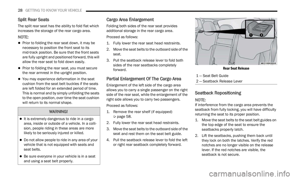
. Pull the seatback release lever to fold both sides
of the rear seatbacks completely
forward.
Partial Enlargement Of The Cargo Area
Enlargement of the left side of the cargo area
allows you to carry a single passenger on the right
side of the rear seat, while the enlargement of the
right side allows you to carry two passengers.
Proceed as follows:
1. Remove the rear shelf (if equipped)
Ú
pag e
58.
2. F ully lower the rear seat head restraints.
3. Move
the seat belts to the outboard side of the
seat
and rest them on the seat belt guide.
4. Pull the seatback release lever to fold the left or rig
ht rear seatback completely forward.
Rear Seat Release
Seatback Repositioning
NOTE:
If interference from the cargo area prevents the
seatb a
ck from fully locking, you will have difficulty
returning the seat to its proper position.
1. Move the seat belts to the seat belt guides on the t o
p edge of the seat to ensure the
seatbacks properly latch.
2. Lift the seatbacks, pushing them back until they
lock on both the latches. Verify the red
notches are no longer visible on the release
lever. If the red notches are visible, the
seatback is not secure.
WARNING!
It is extremely dangerous to ride in a cargo
area, inside or outside of a vehicle. In a colli -
sion, people riding in these areas are more
l ikely
to be seriously injured or killed.
Do not allow people to ride in any area of your
vehicle that is not equipped with seats and
seat belts.
Be sure everyone in your vehicle is in a seat
and using a seat belt properly.
1 — Seat Belt Guide
2 — Seatback Release Lever
Page 31 of 364
GETTING TO KNOW YOUR VEHICLE 29
POWER ADJUSTMENT (FRONT) —
I
F EQUIPPED
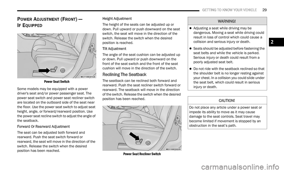
Power Seat Switch
Some models may be equipped with a power
driver
's seat and/or power passenger seat. The
power seat switch and power seat recliner switch
are located on the outboard side of the seat near
the floor. Use the power seat switch to adjust seat
height, angle, or forward/rearward position. Use
the power seat recline switch to adjust the angle of
the seatback.
Forward Or Rearward Adjustment
The seat can be adjusted both forward and
rearw a
rd. Push the seat switch forward or
rearward, the seat will move in the direction of the
switch. Release the switch when the desired
position has been reached. Height Adjustment
The height of the seats can be adjusted up or
d
own. P
ull upward or push downward on the seat
switch, the seat will move in the direction of the
switch. Release the switch when the desired
position is reached.
Tilt Adjustment
The angle of the seat cushion can be adjusted up
or down .
Pull upward or push downward on the
front of the seat switch and the front of the seat
cushion will move in the direction of the switch.
Reclining The Seatback
The seatback can be reclined both forward and
rearward. Push the seat recliner switch forward or
rearward. The seatback will move in the direction
of the switch. Release the switch when the desired
position has been reached.
Power Seat Recliner Switch
WARNING!
Adjusting a seat while driving may be
dangerous. Moving a seat while driving could
result in loss of control which could cause a
collision and serious injury or death.
Seats should be adjusted before fastening the
seat belts and while the vehicle is parked.
Serious injury or death could result from a
poorly adjusted seat belt.
Do not ride with the seatback reclined so that
the shoulder belt is no longer resting against
your chest. In a collision you could slide under
the seat belt, which could result in serious
injury or death.
CAUTION!
Do not place any article under a power seat or
impede its ability to move as it may cause
damage to the seat controls. Seat travel may
become limited if movement is stopped by an
obstruction in the seat’s path.
2
Page 32 of 364
30 GETTING TO KNOW YOUR VEHICLE
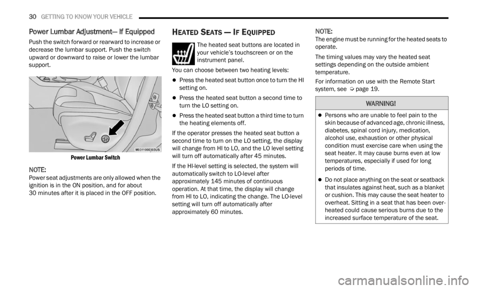
Power Lumbar Adjustment— If Equipped
Push the switch forward or rearward to increase or
decrease the lumbar support. Push the switch
upward or downward to raise or lower the lumbar
support.
Power Lumbar Switch
NOTE:
Power seat adjustments are only allowed when the
ignit i
on is in the ON position, and for about
30 minutes after it is placed in the OFF position.
HEATED SEATS — IF EQUIPPED
The heated seat buttons are located in
your vehicle’s touchscreen or on the
instr u
ment panel.
You can choose between two heating levels:
Press the heated seat button once to turn the HI
setting on.
Press the heated seat button a second time to
turn the LO setting on.
Press the heated seat button a third time to turn
the heating elements off.
If the operator presses the heated seat button a
second
time to turn on the LO setting, the display
will change from HI to LO, and the LO level setting
will turn off automatically after 45 minutes.
If the HI-level setting is selected, the system will
a utomat
ically switch to LO-level after
approximately 145 minutes of continuous
operati
on. At that time, the display will change
from HI to LO, indicating the change. The LO-level
setting will turn off automatically after
approximately 60 minutes.
NOTE:
The engine must be running for the heated seats to
operat e
.
The timing values may vary the heated seat
settin
gs depending on the outside ambient
temperature.
For information on use with the Remote Start
syste m
, see Ú page 19.
WARNING!
Persons who are unable to feel pain to the
skin because of advanced age, chronic illness,
diabetes, spinal cord injury, medication,
alcohol use, exhaustion or other physical
condition must exercise care when using the
seat heater. It may cause burns even at low
temperatures, especially if used for long
periods of time.
Do not place anything on the seat or seatback
that insulates against heat, such as a blanket
or cushion. This may cause the seat heater to
overheat. Sitting in a seat that has been over
-
heated could cause serious burns due to the
i ncrea
sed surface temperature of the seat.
Page 33 of 364
GETTING TO KNOW YOUR VEHICLE 31
UNFOLDING THE REAR ARMREST
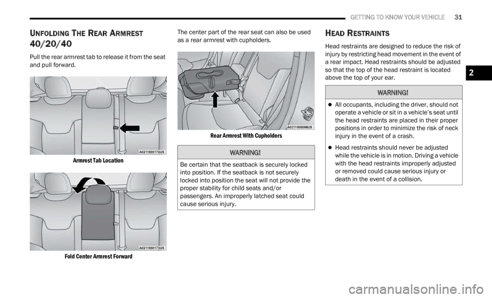
40/20/40
Pull the rear armrest tab to release it from the seat
and pull forward.
Armrest Tab Location
Fold Center Armrest Forward
The center part of the rear seat can also be used
a
s a r
ear armrest with cupholders.
Rear Armrest With Cupholders
HEAD RESTRAINTS
Head restraints are designed to reduce the risk of
injury by restricting head movement in the event of
a rear impact. Head restraints should be adjusted
so that the top of the head restraint is located
above the top of your ear.
WARNING!
Be certain that the seatback is securely locked
into position. If the seatback is not securely
locked into position the seat will not provide the
proper stability for child seats and/or
passengers. An improperly latched seat could
cause serious injury.
WARNING!
All occupants, including the driver, should not
operate a vehicle or sit in a vehicle’s seat until
the head restraints are placed in their proper
positions in order to minimize the risk of neck
injury in the event of a crash.
Head restraints should never be adjusted
while the vehicle is in motion. Driving a vehicle
with the head restraints improperly adjusted
or removed could cause serious injury or
death in the event of a collision.
2
Page 34 of 364
32 GETTING TO KNOW YOUR VEHICLE
Front Head Restraints
Your vehicle is equipped with front driver and
passenger head restraints.
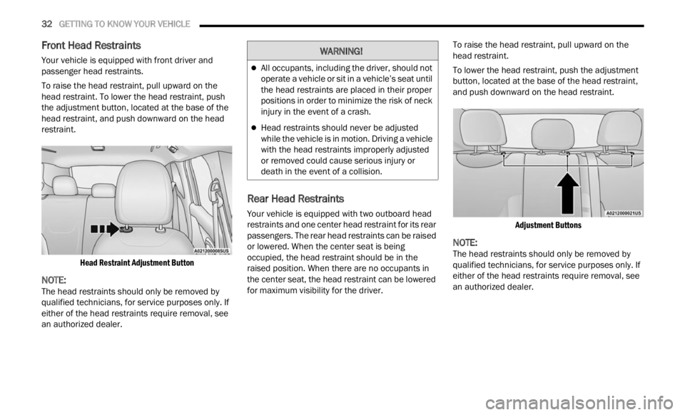
To raise the head restraint, pull upward on the
head r
estraint. To lower the head restraint, push
the adjustment button, located at the base of the
head restraint, and push downward on the head
restraint.
Head Restraint Adjustment Button
NOTE:
The head restraints should only be removed by
quali f
ied technicians, for service purposes only. If
either of the head restraints require removal, see
an authorized dealer.
Rear Head Restraints
Your vehicle is equipped with two outboard head
restraints and one center head restraint for its rear
passengers. The rear head restraints can be raised
or lowered. When the center seat is being
occupied, the head restraint should be in the
raised position. When there are no occupants in
the center seat, the head restraint can be lowered
for maximum visibility for the driver. To raise the head restraint, pull upward on the
head
r
estraint.
To lower the head restraint, push the adjustment
button,
located at the base of the head restraint,
and push downward on the head restraint.
Adjustment Buttons
NOTE:
The head restraints should only be removed by
quali f
ied technicians, for service purposes only. If
either of the head restraints require removal, see
an authorized dealer.
WARNING!
All occupants, including the driver, should not
operate a vehicle or sit in a vehicle’s seat until
the head restraints are placed in their proper
positions in order to minimize the risk of neck
injury in the event of a crash.
Head restraints should never be adjusted
while the vehicle is in motion. Driving a vehicle
with the head restraints improperly adjusted
or removed could cause serious injury or
death in the event of a collision.
Page 39 of 364
GETTING TO KNOW YOUR VEHICLE 37
Turning on the headlights will illuminate the
instrument cluster and the controls located on the
instrument panel.
NOTE:
On vehicles sold in Canada, both the rear position
light s
and Daytime Running Lights (DRLs) will turn
on when the headlight switch is rotated to the O
(off) position.
DAYTIME RUNNING LIGHTS (DRLS) —
I
F EQUIPPED
The Daytime Running Lights (DRLs), if enabled
through Uconnect Settings, will turn on when the
instrument cluster is on and remain on unless the
headlights are turned on or the instrument cluster
is switched off.
NOTE:
For vehicles sold in Canada, the Daytime
Running Lights will automatically deactivate
when the front fog lights are turned on.
On some vehicles, the Daytime Running Lights
may deactivate, or reduce intensity, on one side
of the vehicle (when a turn signal is activated on
that side), or on both sides of the vehicle (when
the hazard warning lights are activated).
HIGH BEAMS
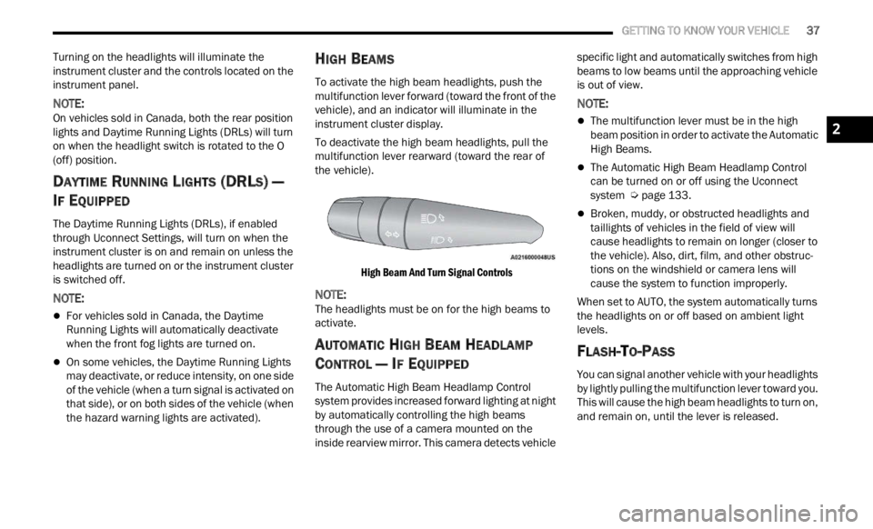
To activate the high beam headlights, push the
multifunction lever forward (toward the front of the
vehicle), and an indicator will illuminate in the
instrument cluster display.
To deactivate the high beam headlights, pull the
multif
unction lever rearward (toward the rear of
the vehicle).
High Beam And Turn Signal Controls
NOTE:
The headlights must be on for the high beams to
activ a
te.
AUTOMATIC HIGH BEAM HEADLAMP
C
ONTROL — IF EQUIPPED
The Automatic High Beam Headlamp Control
system provides increased forward lighting at night
by automatically controlling the high beams
through the use of a camera mounted on the
inside rearview mirror. This camera detects vehicle specific light and automatically switches from high
beams to low beams until the approaching vehicle
is out of view.
NOTE:
The multifunction lever must be in the high
beam position in order to activate the Automatic
High Beams.
The Automatic High Beam Headlamp Control
can be turned on or off using the Uconnect
system
Ú page 133.
Broken, muddy, or obstructed headlights and
taillights of vehicles in the field of view will
cause headlights to remain on longer (closer to
the vehicle). Also, dirt, film, and other obstruc
-
tions on the windshield or camera lens will
c ause
the system to function improperly.
When set to AUTO, the system automatically turns
the he
adlights on or off based on ambient light
levels.
FLASH-TO-PASS
You can signal another vehicle with your headlights
by lightly pulling the multifunction lever toward you.
This will cause the high beam headlights to turn on,
and remain on, until the lever is released.
2
Page 44 of 364
42 GETTING TO KNOW YOUR VEHICLE
WINDSHIELD WIPER OPERATION
Rotate the windshield wiper knob to one of the two
detent positions for intermittent settings, the third
detent for low wiper operation and the fourth for
high wiper operation.
Windshield Washer Operation
To use the washer, pull the lever toward you and
hold w h
ile spray is desired. If the lever is pulled
while in the intermittent setting, the wipers will turn
on and operate for several wipe cycles after the
lever is released, and then resume the intermittent
interval previously selected.
If the lever is pulled while the wipers are in the off
positi on
, the wipers will operate for several wipe
cycles, then turn off. Mist
Use this feature when weather conditions make
occasi
on
al usage of the wipers necessary. Push
the lever upward to the MIST position and release
for a single wiping cycle.
NOTE:
The Mist feature does not activate the washer
pump;
therefore, no washer fluid will be sprayed on
the windshield. The wash function must be used in
order to spray the windshield with washer fluid.
For information on wiper care and replacement,
see Ú p
age 297 .
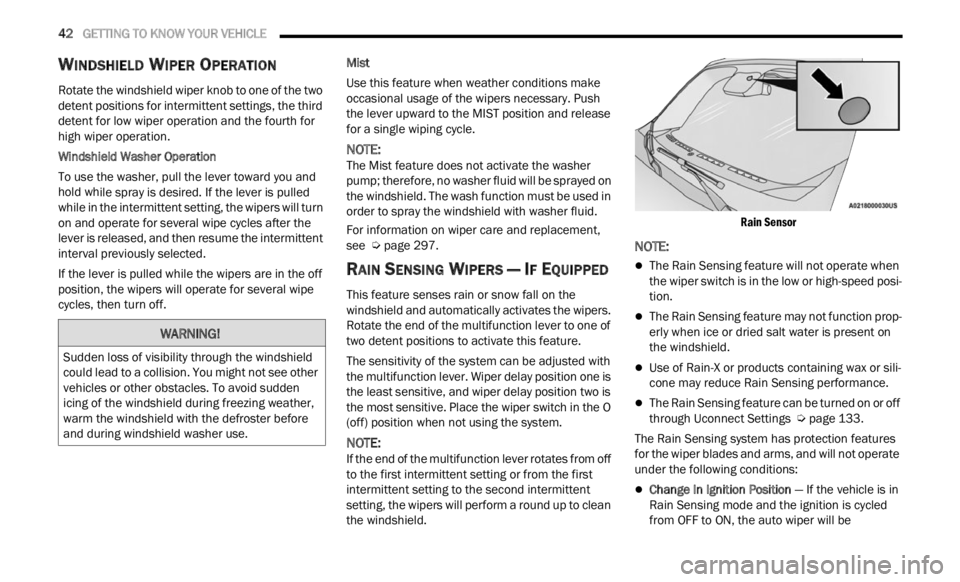
RAIN SENSING WIPERS — IF EQUIPPED
This feature senses rain or snow fall on the
windshield and automatically activates the wipers.
Rotate the end of the multifunction lever to one of
two detent positions to activate this feature.
The sensitivity of the system can be adjusted with
the mu
ltifunction lever. Wiper delay position one is
the least sensitive, and wiper delay position two is
the most sensitive. Place the wiper switch in the O
(off) position when not using the system.
NOTE:
If the end of the multifunction lever rotates from off
to the
first intermittent setting or from the first
intermittent setting to the second intermittent
setting, the wipers will perform a round up to clean
the windshield.
Rain Sensor
NOTE:
The Rain Sensing feature will not operate when
the wiper switch is in the low or high-speed posi
-
tion.
The Rain Sensing feature may not function prop -
erly when ice or dried salt water is present on
t h e
w
i
ndshield.
Use of Rain-X or products containing wax or sili-
cone may reduce Rain Sensing performance.
The Rain Sensing feature can be turned on or off
through Uconnect Settings Ú page 133.
The Rain Sensing system has protection features
f or the
wiper blades and arms, and will not operate
under the following conditions:
Change In Ignition Position — If the vehicle is in
Rain Sensing mode and the ignition is cycled
from OFF to ON, the auto wiper will be
WARNING!
Sudden loss of visibility through the windshield
could lead to a collision. You might not see other
vehicles or other obstacles. To avoid sudden
icing of the windshield during freezing weather,
warm the windshield with the defroster before
and during windshield washer use.
Page 51 of 364
GETTING TO KNOW YOUR VEHICLE 49
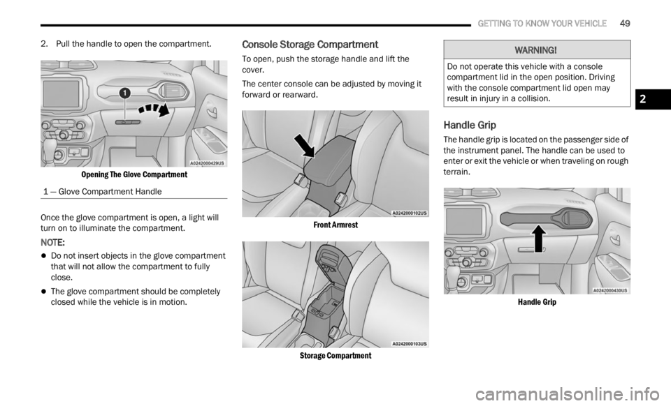
2. Pull the handle to open the compartment.
Opening The Glove Compartment
Once the glove compartment is open, a light will
turn on
to illuminate the compartment.
NOTE:
Do not insert objects in the glove compartment
that will not allow the compartment to fully
close.
The glove compartment should be completely
closed while the vehicle is in motion.
Console Storage Compartment
To open, push the storage handle and lift the
cover.
The center console can be adjusted by moving it
forward
or rearward.
Front Armrest
Storage Compartment
Handle Grip
The handle grip is located on the passenger side of
the instrument panel. The handle can be used to
enter or exit the vehicle or when traveling on rough
terrain.
Handle Grip
1 — Glove Compartment Handle
WARNING!
Do not operate this vehicle with a console
compartment lid in the open position. Driving
with the console compartment lid open may
result in injury in a collision.
2
Page 52 of 364
50 GETTING TO KNOW YOUR VEHICLE
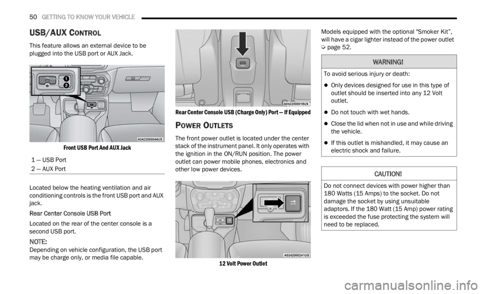
USB/AUX CONTROL
This feature allows an external device to be
plugged into the USB port or AUX Jack.
Front USB Port And AUX Jack
Located below the heating ventilation and air
condit i
oning controls is the front USB port and AUX
jack.
Rear Center Console USB Port
Located on the rear of the center console is a
s econd
USB port.
NOTE:
Depending on vehicle configuration, the USB port
may b e
charge only, or media file capable.
Rear Center Console USB (Charge Only) Port — If Equipped
POWER OUTLETS
The front power outlet is located under the center
stack of the instrument panel. It only operates with
the ignition in the ON/RUN position. The power
outlet can power mobile phones, electronics and
other low power devices.
12 Volt Power Outlet
Models equipped with the optional "Smoker Kit”,
will h
ave a cigar lighter instead of the power outlet
Ú page 52.
1 — USB Port
2 — AUX Port
WARNING!
To avoid serious injury or death:
Only devices designed for use in this type of
outlet should be inserted into any 12 Volt
outlet.
Do not touch with wet hands.
Close the lid when not in use and while driving
the vehicle.
If this outlet is mishandled, it may cause an
electric shock and failure.
CAUTION!
Do not connect devices with power higher than
180 Watts (15 Amps) to the socket. Do not
damage the socket by using unsuitable
adaptors. If the 180 Watt (15 Amp) power rating
is exceeded the fuse protecting the system will
need to be replaced.