warning light JEEP RENEGADE 2023 Service Manual
[x] Cancel search | Manufacturer: JEEP, Model Year: 2023, Model line: RENEGADE, Model: JEEP RENEGADE 2023Pages: 364, PDF Size: 18.65 MB
Page 208 of 364

206 MULTIMEDIA
(Continued)
recorded or monitored for quality assurance
purposes. Through your enrollment in and use of
the SiriusXM Guardian™ connected services, you
consent to being recorded.
SOS Call System Limitations
Vehicles that have been purchased in the US and
that tr
avel into Mexico and Canada may have
limited services. In particular, responses to SOS
calls or other emergency services may be
unavailable or very limited. Vehicles purchased
outside the United States and Canada are unable to
receive SiriusXM Guardian™ connected services.
If the SOS Call system detects a malfunction, any
of the
following may occur at the time the
malfunction is detected:
The light will continuously be illuminated red.
The screen will display the following message
“Vehicle phone requires service. Please contact
your dealer.”
An in-vehicle audio message will state “Vehicle
phone requires service. Please contact your
dealer.”
Even if the SOS Call system is fully functional,
factor s
beyond FCA US LLC’s control may prevent
or stop SOS Call system operation. These include,
but are not limited to, the following factors:
The ignition key is in OFF position.
The vehicle’s electrical systems are not intact.
The vehicle battery loses power or becomes
disconnected during a vehicle crash.
The SOS Call system software and/or hardware
is damaged during a vehicle crash.
LTE (voice/data) or 3G or 4G (data) coverage
and/or GPS signals are unavailable or
obstructed.
Network congestion.
Weather conditions.
Buildings, structures, geographic terrain, or
tunnels.
If your vehicle loses battery power for any reason
(incl u
ding during or after an accident), the SOS Call
system, among other vehicle systems, will not
operate.
Requirements
This feature is available only on vehicles sold in
the US or Canada.
Vehicle must be properly equipped with the
SiriusXM Guardian™ connected services.
Vehicle must be registered with SiriusXM
Guardian™ and have an active subscription that
includes the applicable feature.
Vehicle must have an operable LTE (voice/data)
or 3G or 4G (data) network connection compat -
ible with your device.
Vehicle must be powered in the ON/RUN or ACC
(Accessory) position with a properly functioning
electrical system.
WARNING!
Never place anything on or near the vehicle’s
LTE (voice/data) or 3G or 4G (data) and GPS
antennas. You could prevent LTE (voice/data)
or 4G (data) and GPS signal reception, which
can prevent your vehicle from placing an
emergency call.
Do not add any aftermarket electrical equip -
ment to the vehicle’s electrical system. This
may p r
event your vehicle from sending a
signal to initiate an emergency call. To avoid
interference that can cause the SOS Call
system to fail, never add aftermarket equip -
ment (e.g., two-way mobile radio, CB radio,
data r
ecorder, etc.) to your vehicle’s electrical
system or modify the antennas on your
vehicle. IF YOUR VEHICLE LOSES POWER FOR
ANY REASON (INCLUDING DURING OR AFTER
AN ACCIDENT), NEITHER THE MOBILE APPS
NOR THE SIRIUSXM GUARDIAN™ CONNECTED
SERVICES WILL OPERATE.
Page 209 of 364
MULTIMEDIA 207
Automatic SOS — If Equipped
Automatic SOS is a hands-free safety service that
can immediately connect you with help in the event
that your vehicle’s airbags deploy. After an
accident, a live agent will contact you through the
Uconnect system and alert emergency services.
NOTE:
An active SiriusXM Guardian™ subscription is
requi r
ed for this feature to function.
After a crash where the airbags deploy:
1. Automatic SOS will initiate a call with an agen t
.
2. An agent will receive the call and confirm the locati
on of the emergency.
3. If needed, the agent will request the assis
tance of emergency services.
4. First responders will arrive on scene. The agent
will remain on the call until emergency
services arrive.
NOTE:
Agents are available 24/7 to assist you in the
case of an emergency.
On your behalf, agents are able to notify family
members about the collision.
Agents can brief first responders of the situation
before they arrive on scene.
In the event vehicle occupants are unable to
speak, emergency services will be dispatched
based on the last known GPS coordinates.
SiriusXM Guardian™ connected services are
dependent upon an operative telematics
device, a cellular connection, navigation map
data, and GPS satellite reception, which can
limit the ability to reach the response center or
reach emergency support.
Terms of service of the Uconnect and the
SiriusXM Guardian™ subscriber agreement
apply. See terms of services for complete
service limitation.
Remote Commands
On the Remote Commands screen, you have
access to several vehicle features that can be
controlled remotely from your mobile device. These
features include locking/unlocking, remote
starting, and activating the horn and lights of the
vehicle.
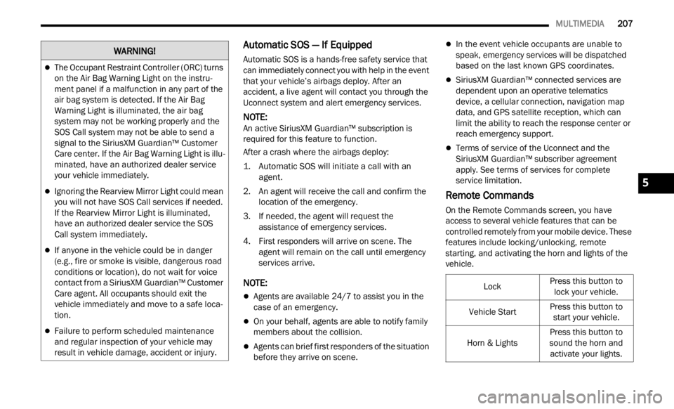
The Occupant Restraint Controller (ORC) turns
on the Air Bag Warning Light on the instru -
ment panel if a malfunction in any part of the
a ir ba
g system is detected. If the Air Bag
Warning Light is illuminated, the air bag
system may not be working properly and the
SOS Call system may not be able to send a
signal to the SiriusXM Guardian™ Customer
Care center. If the Air Bag Warning Light is illu -
minated, have an authorized dealer service
your v e
hicle immediately.
Ignoring the Rearview Mirror Light could mean
you will not have SOS Call services if needed.
If the Rearview Mirror Light is illuminated,
have an authorized dealer service the SOS
Call system immediately.
If anyone in the vehicle could be in danger
(e.g., fire or smoke is visible, dangerous road
conditions or location), do not wait for voice
contact from a SiriusXM Guardian™ Customer
Care agent. All occupants should exit the
vehicle immediately and move to a safe loca -
tion.
Failure to perform scheduled maintenance
and regular inspection of your vehicle may
result in vehicle damage, accident or injury.
WARNING!
LockPress this button to lock your vehicle.
Vehicle Start Press this button to
start
your vehicle.
Horn & Lights Press this button to
s ound
t
he horn and
activate your lights.
5
Page 213 of 364

MULTIMEDIA 211
regulatory requirements. You acknowledge, agree
and consent to any recording, monitoring or
sharing of information obtained through any such
call recordings.
Send & Go — If Equipped
Description
The Send & Go feature allows you to search for a
destin
ation on your mobile device, and then send
the route to your vehicle’s Navigation system.
How It Works
1. T here are multiple ways to find a destination.
After s
electing the Location tab at the bottom
of the App, browse through one of the
categories provided, or type the name or
keyword in the search box. You can also
select categories such as “Favorites” or
“Contact List”.
2. Select your destination from the list that appe a
rs. Location information will then be
displayed on the map.
From this screen, you will be able to:
View the location on a map.
See the distance from your current location.
Send the destination to the vehicle (Send &
Go).
3. Send the destination to the Uconnect Navig
ation in your vehicle. You can also call
the destination by pressing the Call button. 4. Confirm your destination in the vehicle through
a not i
fication or in the Navigation system.
Requirements
Vehicle must have an operable LTE (voice/data)
or 3G or 4G (data) network connection compat -
ible with your device.
Vehicle must have an active subscription that
includes the applicable feature.
Vehicle Finder
Description
The Vehicle Finder feature allows you to find the
locati on
of your vehicle.
You can also sound the horn and flash the lights to
make f
inding your vehicle even easier.
How It Works
Select the Vehicle Finder function within the
Mobile
App and select the Location tab at the
bottom of the App. Then, press the Vehicle icon to
find your vehicle.
Requirements
Vehicle must be properly equipped with the
Uconnect system.
Vehicle must have an operable LTE (voice/data)
or 3G or 4G (data) network connection compat -
ible with your device.
Vehicle must have an active subscription that
includes the applicable feature.
Vehicle ignition must have been turned on
within 14 days.
4G Wi-Fi Hotspot — If Equipped
Description
4G Wi-Fi Hotspot is an in-vehicle service that
connec t
s your device to an LTE (voice/data) or 4G
(data) network that is ready to go wherever you are.
After you've made your purchase, turn on your
device’s Wi-Fi and connect your devices.
Enables all your passengers to be simultane -
ously connected to the web.
Connect several devices at one time.
Any Wi-Fi-enabled device — such as a laptop or
any other portable-enabled media — can
connect over your private in-vehicle network.
A high-speed, secured connection lets anyone
on your private network access the Web — great
for working and relaxing.
WARNING!
The driver should NEVER use the 4G Wi-Fi
Hotspot while driving the vehicle as doing so
may result in an accident involving serious injury
or death.
5
Page 223 of 364
221
(Continued)
SAFETY
SAFETY FEATURES
ANTI-LOCK BRAKE SYSTEM (ABS)
ABS provides increased vehicle stability and brake
performance under most braking conditions. The
system automatically prevents wheel lock and
enhances vehicle control during braking.
The ABS performs a self-check cycle to ensure that
the AB
S is working properly each time the vehicle
is started and driven. During this self-check, you
may hear a slight clicking sound as well as some
related motor noises.
The ABS is activated during braking when the
syste m
detects one or more wheels are beginning
to lock. Road conditions such as ice, snow, gravel,
bumps, railroad tracks, loose debris, or panic stops
may increase the likelihood of ABS activation(s).
You also may experience the following normal
chara c
teristics when the ABS activates:
ABS motor noise or clicking sounds (you may
continue to hear for a short time after the stop)
Brake pedal pulsations
A slight drop of the brake pedal at the end of the
stop ABS is designed to function with the Original
Equip
m
ent Manufacturer (OEM) tires. Modification
may result in degraded ABS performance.
Anti-Lock Brake System (ABS) Warning
Light
The yellow ABS Warning Light will turn on when the
ignition is placed in the ON/RUN mode and may
stay on for as long as four seconds.
If the ABS Warning Light remains on or comes on
while
driving, it indicates that the anti-lock portion
of the brake system is not functioning and that
service is required. However, the conventional
brake system will continue to operate normally if
the ABS Warning Light is on.
WARNING!
The ABS contains sophisticated electronic
equipment that may be susceptible to interfer -
ence caused by improperly installed or high
output
radio transmitting equipment. This
interference can cause possible loss of
anti-lock braking capability. Installation of
such equipment should be performed by qual -
ified professionals.
Pumping of the Anti-Lock Brakes will diminish
their effectiveness and may lead to a collision.
Pumping makes the stopping distance longer.
Just press firmly on your brake pedal when you
need to slow down or stop.
The ABS cannot prevent the natural laws of
physics from acting on the vehicle, nor can it
increase braking or steering efficiency beyond
that afforded by the condition of the vehicle
brakes and tires or the traction afforded.
The ABS cannot prevent collisions, including
those resulting from excessive speed in turns,
following another vehicle too closely, or hydro -
planing.
The capabilities of an ABS equipped vehicle
must never be exploited in a reckless or
dangerous manner that could jeopardize the
user’s safety or the safety of others.
WARNING!
6
Page 224 of 364
222 SAFETY
If the ABS Warning Light is on, the brake system
should be serviced as soon as possible to restore
the benefits of Anti-Lock Brakes. If the ABS
Warning Light does not come on when the ignition
is placed in the ON/RUN mode, have the light
repaired as soon as possible.
ELECTRONIC BRAKE CONTROL (EBC)
S
YSTEM
Your vehicle is equipped with an advanced
Electronic Brake Control (EBC) system. This system
includes Anti-Lock Brake System (ABS), Brake
Assist System (BAS), Electronic Roll Mitigation
(ERM), Electronic Stability Control (ESC), Hill Start
Assist (HSA) and Traction Control System (TCS).
These systems work together to enhance both
vehicle stability and control in various driving
conditions.
Your vehicle may also be equipped with Dynamic
Steer i
ng Torque (DST), Hill Descent Control (HDC)
and Trailer Sway Control (TSC).
Brake Assist System (BAS)
The BAS is designed to optimize the vehicle’s
braking capability during emergency braking
maneuvers. The system detects an emergency
braking situation by sensing the rate and amount
of brake application and then applies optimum
pressure to the brakes. This can help reduce
braking distances. The BAS complements the Anti-Lock Brake System (ABS). Applying the brakes
very quickly results in the best BAS assistance. To
receive the benefit of the system, you must apply
continuous braking pressure during the stopping
sequence (do not “pump” the brakes). Do not
reduce brake pedal pressure unless braking is no
longer desired. Once the brake pedal is released,
the BAS is deactivated.Dynamic Steering Torque (DST)
DST uses the integration of the Electronic Stability
Control (ESC) system with the electric power
steering to increase the safety level of the whole
vehicle. In critical situations (understeering,
oversteering, braking with different grip
conditions), through the DST function the ESC
system controls the steering to implement an additional torque contribution on the steering
wheel, to suggest the most correct maneuver to
the driver. The coordinated action of brakes and
steering increases the safety and feeling of vehicle
control.
NOTE:
The DST is a driving aid system and does not
repla c
e the driver’s actions while driving the car.
Electronic Roll Mitigation (ERM)
ERM anticipates the potential for wheel lift by
monitoring the driver’s steering wheel input and
the speed of the vehicle. When Electronic Roll
Mitigation (ERM) determines that the rate of
change of the steering wheel angle and vehicle's
speed are sufficient to potentially cause wheel lift,
it then applies the appropriate brake and may also
reduce engine power to lessen the chance that
wheel lift will occur. ERM can only reduce the
chance of wheel lift occurring during severe or
evasive driving maneuvers, and it will only
intervene during these types of maneuvers. It
cannot prevent wheel lift due to other factors, such
as road conditions, leaving the roadway, or striking
objects or other vehicles.
NOTE:
ERM is disabled any time the ESC is in “Full Off”
mode. F
or a complete explanation of the available
ESC modes, see Ú page 223.
WARNING!
The Brake Assist System (BAS) cannot prevent
the natural laws of physics from acting on the
vehicle, nor can it increase the traction afforded
by prevailing road conditions. BAS cannot
prevent collisions, including those resulting from
excessive speed in turns, driving on very slippery
surfaces, or hydroplaning. The capabilities of a
BAS-equipped vehicle must never be exploited in
a reckless or dangerous manner, which could
jeopardize the user's safety or the safety of
others.
Page 225 of 364
SAFETY 223
Electronic Stability Control (ESC)
ESC enhances directional control and stability of
the vehicle under various driving conditions. ESC
corrects for oversteering or understeering of the
vehicle by applying the brake of the appropriate
wheel(s) to counteract the above conditions.
Engine power may also be reduced to help the
vehicle maintain the desired path.
Oversteer — when the vehicle is turning more
than appropriate for the steering wheel position.
Understeer — when the vehicle is turning less
than appropriate for the steering wheel position.
ESC uses sensors in the vehicle to determine the
vehicl
e path intended by the driver and compares
it to the actual path of the vehicle. When the actual
path does not match the intended path, ESC
applies the brake of the appropriate wheel to
assist in counteracting the oversteer or understeer
condition.
The ESC Activation/Malfunction Indicator Light
locate d
in the instrument cluster will start to flash
as soon as the ESC system becomes active. The
ESC Activation/Malfunction Indicator Light also
flashes when the TCS is active. If the ESC
Activation/Malfunction Indicator Light begins to
flash during acceleration, ease up on the
accelerator and apply as little throttle as possible.
Be sure to adapt your speed and driving to the
prevailing road conditions.
WARNING!
Many factors, such as vehicle loading, road
conditions, and driving conditions, influence the
chance that wheel lift or rollover may occur.
Electronic Roll Mitigation (ERM) cannot prevent
all wheel lift or rollovers, especially those that
involve leaving the roadway or striking objects or
other vehicles. The capabilities of an
ERM-equipped vehicle must never be exploited
in a reckless or dangerous manner, which could
jeopardize the user's safety or the safety of
others.
WARNING!
Electronic Stability Control (ESC) cannot
prevent the natural laws of physics from acting
on the vehicle, nor can it increase the traction
afforded by prevailing road conditions. ESC
cannot prevent accidents, including those
resulting from excessive speed in turns, driving
on very slippery surfaces, or hydroplaning. ESC
also cannot prevent accidents resulting from
loss of vehicle control due to inappropriate
driver input for the conditions. Only a safe,
attentive, and skillful driver can prevent acci -
dents. The capabilities of an ESC equipped
vehic l
e must never be exploited in a reckless or
dangerous manner which could jeopardize the
user’s safety or the safety of others.
Vehicle modifications, or failure to properly
maintain your vehicle, may change the handling
characteristics of your vehicle, and may nega -
tively affect the performance of the ESC system.
Chang e
s to the steering system, suspension,
braking system, tire type and size or wheel size
may adversely affect ESC performance. Improp -
erly inflated and unevenly worn tires may also
d egrad
e ESC performance. Any vehicle modifi-
cation or poor vehicle maintenance that
r educe
s the effectiveness of the ESC system
can increase the risk of loss of vehicle control,
vehicle rollover, personal injury and death.
6
Page 226 of 364
224 SAFETY
ESC Operation Modes
To disable ESC and other safety systems, follow
the instructions below.
There are three modes of active safety systems
presen
t on the vehicle:
ESC On
Partial Off
Full Off
ESC On – Two-Wheel Drive Vehicles And
Four-W h
eel Drive Vehicles In 2WD And 4WD High
This is the normal operating mode for ESC when
operati
ng a two-wheel drive vehicle. It is also the
normal mode for operating a four-wheel drive
vehicle in 2WD or 4WD High. The ESC system will
be in “ESC On” mode whenever the vehicle is
started or the power transfer unit (if equipped) is
shifted out of 4WD Low. This mode should be used
for most driving situations. ESC should only be
turned to “Partial Off” or “Full Off” for specific
reasons as noted. Refer to “Partial Off” and to “Full
Off” for additional information.
NOTE:
It is recommended to select the mode "Partial Off"
or "Fu l
l Off" only for specific reasons.
Partial Off – Two-Wheel Drive Vehicles And
Four-Wh
eel Drive Vehicles In 2WD And 4WD High
The “Partial Off” mode is intended for driving in
deep s
now, sand, or gravel. This mode raises the threshold for TCS and ESC activation, which allows
for more wheel spin than what ESC normally
allows.
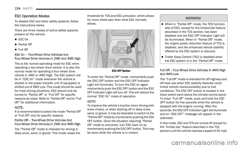
ESC OFF Button
To enter the “Partial Off” mode, momentarily push
the E S
C OFF button and the ESC OFF Indicator
Light will illuminate. To turn the ESC on again,
momentarily push the ESC OFF button and the ESC
OFF Indicator Light will turn off. This will restore the
normal “ESC On” mode of operation.
NOTE:
To improve the vehicle’s traction when driving with
snow c h
ains, or when starting off in deep snow,
sand, or gravel, it may be desirable to switch to the
“Partial Off” mode by momentarily pushing the ESC
OFF button. Once the situation requiring “Partial
Off” mode is overcome, turn ESC back on by
momentarily pushing the ESC OFF button. This may
be done while the vehicle is in motion. Full Off – Four-Wheel Drive Vehicles In 4WD High
And 4
W
D Low
The “Full Off” mode is intended for off-highway and
off-road
use when ESC stability features could
inhibit vehicle maneuverability due to trail
conditions. The ESC OFF button is located in the
lower switch bank above the climate control panel.
To enter “Full Off” mode, push and hold the ESC
OFF button for five seconds while the vehicle is
stopped with the engine running. After five
seconds, the ESC OFF Indicator Light will illuminate
and an “ESC OFF” message will appear in the
odometer.
In this mode, ESC and TCS are turned off (except for
the “ l
imited slip” feature described in the TCS
section) until the vehicle reaches a speed of 40 mph
WARNING!
When in “Partial Off” mode, the TCS function -
ality of ESC, except for the limited slip feature
descr i
bed in the TCS section, has been
disabled and the ESC OFF Indicator Light will
be illuminated. When in “Partial Off” mode,
the engine power reduction feature of TCS is
disabled, and the enhanced vehicle stability
offered by the ESC system is reduced.
Trailer Sway Control (TSC) is disabled when
the ESC system is in the “Partial Off” mode.
Page 229 of 364
SAFETY 227
Hill Start Assist (HSA)
HSA is designed to help the driver accelerate the
vehicle from a complete stop while on an incline. If
the driver releases the brake while stopped on an
incline, HSA will continue to hold the brake
pressure for a short period. If the driver does not
apply the throttle before this time expires, the
system will release brake pressure and the vehicle
will roll down the hill as normal. The system will
release brake pressure in proportion to amount of
throttle applied.
The following conditions must be met in order for
HSA to a
ctivate:
The vehicle must be stopped.
The vehicle must be on a 5% (approximate)
grade or greater hill.
The gear selection must match vehicle uphill
direction (i.e., vehicle facing uphill is in forward
gear; vehicle backing uphill is in REVERSE gear).
For vehicles equipped with an automatic trans -
mission, the HSA will work in REVERSE gear and all f
or ward gears. The system will not activate if
the transmission is in PARK.
Disabling And Enabling HSA
This feature can be turned on or turned off. To
chang e
the current setting, see Ú page 64.
Traction Control System (TCS)
TCS monitors the amount of wheel spin of each of
the driven wheels. If wheel spin is detected, brake
pressure is applied to the slipping wheel(s) and
engine power is reduced to provide enhanced
acceleration and stability. A feature of the TCS,
Brake Limited Differential (BLD) functions similarly to a limited slip differential and controls the wheel
spin across a driven axle. If one wheel on a driven
axle is spinning faster than the other, the system
will apply the brake of the spinning wheel. This will
allow more engine torque to be applied to the
wheel that is not spinning. This feature remains
active even if TCS and Electronic Stability Control
(ESC) are in the “Partial Off” mode or the “Full Off”
modes. For further information, see
Ú page 223.
Trailer Sway Control (TSC) — If Equipped
TSC uses sensors in the vehicle to recognize an
excessively swaying trailer and will take the
appropriate actions to attempt to stop the sway.
The system may reduce engine power and apply
the brake of the appropriate wheel(s) to counteract
the sway of the trailer.
NOTE:
TSC cannot stop all trailers from swaying. Always
use c a
ution when towing a trailer and follow the
trailer tongue weight recommendations. For
further information, see Ú page 124. When TSC is
functioning, the ESC Activation/Malfunction Indi -
cator Light will flash, the engine power may be
r educ e
d and you may feel the brakes being applied
to individual wheels to attempt to stop the trailer
from swaying. TSC is disabled when the ESC
system is in the “Partial Off” mode.
WARNING!
HDC is only intended to assist the driver in
controlling vehicle speed when descending hills.
The driver must remain attentive to the driving
conditions and is responsible for maintaining a
safe vehicle speed.WARNING!
There may be situations where the Hill Start
Assist (HSA) will not activate and slight rolling
may occur, such as on minor hills or with a
loaded vehicle, or while pulling a trailer. HSA is
not a substitute for active driving involvement. It
is always the driver’s responsibility to be
attentive to distance to other vehicles, people,
and objects, and most importantly brake
operation to ensure safe operation of the vehicle
under all road conditions. Your complete
attention is always required while driving to
maintain safe control of your vehicle. Failure to
follow these warnings can result in a collision or
serious personal injury.
6
Page 230 of 364
228 SAFETY
AUXILIARY DRIVING SYSTEMS
BLIND SPOT MONITORING (BSM) —
I
F EQUIPPED
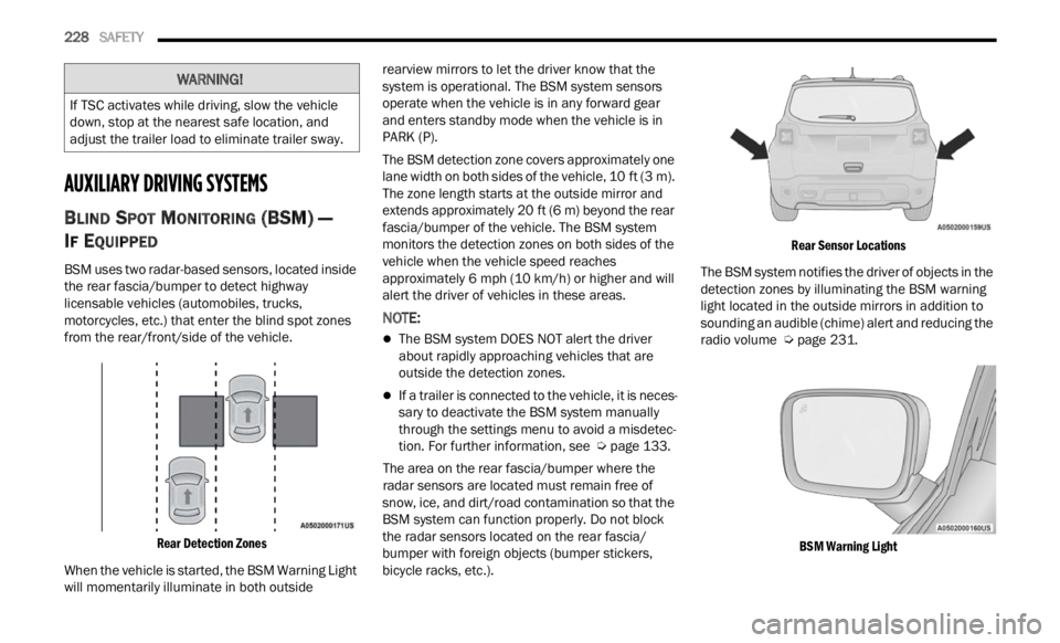
BSM uses two radar-based sensors, located inside
the rear fascia/bumper to detect highway
licensable vehicles (automobiles, trucks,
motorcycles, etc.) that enter the blind spot zones
from the rear/front/side of the vehicle.
Rear Detection Zones
When the vehicle is started, the BSM Warning Light
will m
omentarily illuminate in both outside rearview mirrors to let the driver know that the
system is operational. The BSM system sensors
operate when the vehicle is in any forward gear
and enters standby mode when the vehicle is in
PARK (P).
The BSM detection zone covers approximately one
lane
w
idth on both sides of the vehicle, 10 ft (3 m).
The z on
e length starts at the outside mirror and
extends approximately 20 ft (6 m) beyond the rear
fascia
/bumper of the vehicle. The BSM system
monitors the detection zones on both sides of the
vehicle when the vehicle speed reaches
approximately 6 mph (10 km/h) or higher and will
alert
the driver of vehicles in these areas.
NOTE:
The BSM system DOES NOT alert the driver
about rapidly approaching vehicles that are
outside the detection zones.
If a trailer is connected to the vehicle, it is neces -
sary to deactivate the BSM system manually
t h r
ou g
h
the settings menu to avoid a misdetec -
tion. For further information, see Ú page 133.
The area on the rear fascia/bumper where the
r adar
sensors are located must remain free of
snow, ice, and dirt/road contamination so that the
BSM system can function properly. Do not block
the radar sensors located on the rear fascia/
bumper with foreign objects (bumper stickers,
bicycle racks, etc.).
Rear Sensor Locations
The BSM system notifies the driver of objects in the
detec t
ion zones by illuminating the BSM warning
light located in the outside mirrors in addition to
sounding an audible (chime) alert and reducing the
radio volume Ú page 231.
BSM Warning Light
WARNING!
If TSC activates while driving, slow the vehicle
down, stop at the nearest safe location, and
adjust the trailer load to eliminate trailer sway.
Page 231 of 364
SAFETY 229
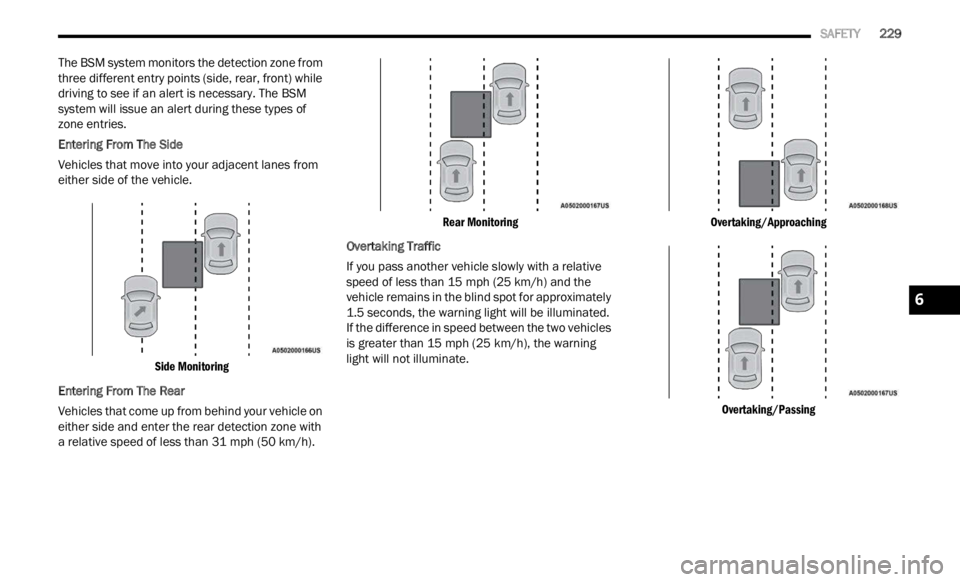
The BSM system monitors the detection zone from
three different entry points (side, rear, front) while
driving to see if an alert is necessary. The BSM
system will issue an alert during these types of
zone entries.
Entering From The Side
Vehicles that move into your adjacent lanes from
e
ithe r
side of the vehicle.
Side Monitoring
Entering From The Rear
Vehicles that come up from behind your vehicle on
either
side and enter the rear detection zone with
a relative speed of less than 31 mph (50 km/h).
Rear Monitoring
Overtaking Traffic
If you pass another vehicle slowly with a relative
s peed
of less than 15 mph (25 km/h) and the
vehic l
e remains in the blind spot for approximately
1.5 seconds, the warning light will be illuminated.
If the difference in speed between the two vehicles
is greater than 15 mph (25 km/h), the warning
light
will not illuminate.
Overtaking/Approaching
Overtaking/Passing
6