warning light JEEP RENEGADE 2023 Manual PDF
[x] Cancel search | Manufacturer: JEEP, Model Year: 2023, Model line: RENEGADE, Model: JEEP RENEGADE 2023Pages: 364, PDF Size: 18.65 MB
Page 290 of 364
288 SERVICING AND MAINTENANCE
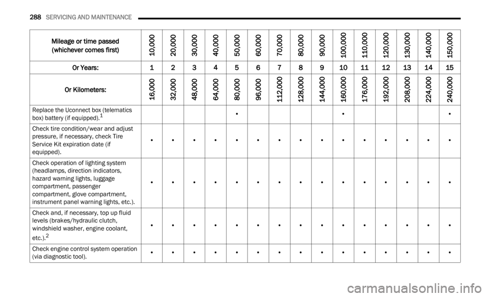
Mileage or time passed
(whichever comes first)
10,000
20,000
30,000
40,000
50,000
60,000
70,000
80,000
90,000
100,000
110,000
120,000
130,000
140,000
150,000
Or Years: 12345678910 1112131415
Or Kilometers:
16,000
32,000
48,000
64,000
80,000
96,000
112,000
128,000
144,000
160,000
176,000
192,000
208,000
224,000
240,000
Replace the Uconnect box (telematics
box) battery (if equipped).1
• ••
Check tire condition/wear and adjust
press u
re, if necessary, check Tire
Service Kit expiration date (if
equipped). •
••••••••••••••
Check operation of lighting system
(head l
amps, direction indicators,
hazard warning lights, luggage
compartment, passenger
compartment, glove compartment,
instrument panel warning lights, etc.). •
••••••••••••••
Check and, if necessary, top up fluid
l evel
s
(brakes/hydraulic clutch,
windshield washer, engine coolant,
etc.).
2
• ••••••••••••••
Check engine control system operation
(via d
iagnostic tool). •
••••••••••••••
Page 293 of 364
SERVICING AND MAINTENANCE 291
○ Recommend replacement
• Mandatory service
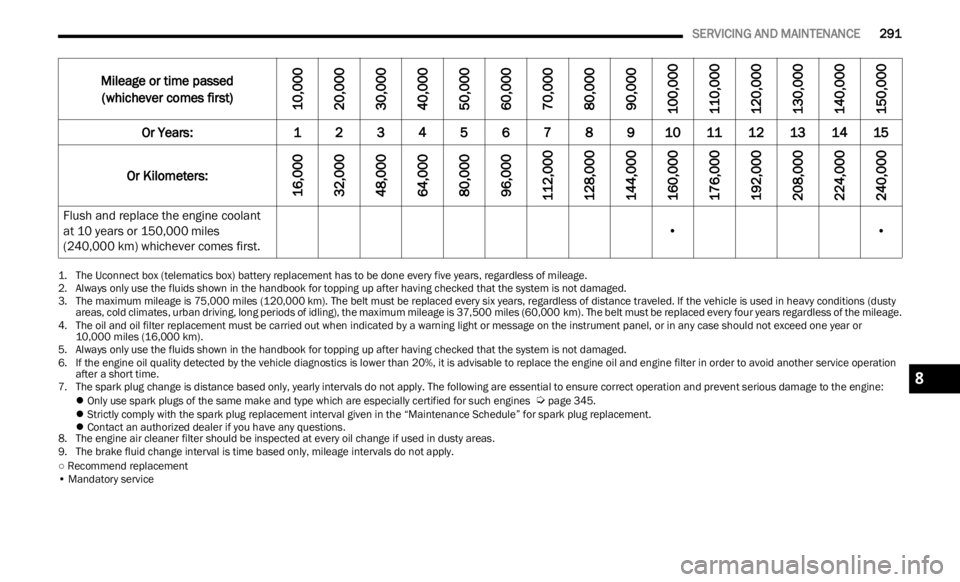
Flush and replace the engine coolant
at 10 years or 150,000 miles
(240,000 km) whichever comes first. •
•
1. The Uconnect box (telematics box) battery replacement has to be done every five years, regardless of mileage.2. Always only use the fluids shown in the handbook for topping up after having checked that the system is not damaged.
3. The maximum mileage is 75,000 mile s (120,000 km). The belt must be replaced every six years, regardless of distance traveled. If the vehicle is used in heavy conditions (dusty
areas,
cold climates, urban driving, long periods of idling), the maximum mileage is 37,500 miles (60,000 km). The belt must be replaced every four years regardless of the mileage.
4. The oil and oil filter replacement must be carried out when indicated by a warning light or message on the instrument panel, or in any case should not exceed one year or
10,0 0
0 miles (16,000 km).
5. Always only use the fluids shown in the handbook for topping up after having checked that the system is not damaged.
6. If
the engine oil quality detected by the vehicle diagnostics is lower than 20%, it is advisable to replace the engine oil and engine filter in order to avoid another service operation
afte r
a short time.
7. The spark plug change is distance based only, yearly intervals do not apply. The following are essential to ensure correct operation and prevent serious damage to the engine:
Only use spark plugs of the same make and type which are especially certified for such engines
Ú page 345 .
Strictly comply with the spark plug replacement interval given in the “Maintenance Schedule” for spark plug replacement.
Contact an authorized dealer if you have any questions.
8. Th e
engine air cleaner filter should be inspected at every oil change if used in dusty areas.
9. The brake fluid change interval is time based only, mileage intervals do not apply.
Mileage or time passed
(whichever comes first)
10,000
20,000
30,000
40,000
50,000
60,000
70,000
80,000
90,000
100,000
110,000
120,000
130,000
140,000
150,000
Or Years: 1 2 3 4 5 6 7 8 9 10 11 12 13 14 15
Or Kilometers:
16,000
32,000
48,000
64,000
80,000
96,000
112,000
128,000
144,000
160,000
176,000
192,000
208,000
224,000
240,000
8
Page 304 of 364
302 SERVICING AND MAINTENANCE
(Continued)
Keep the front of the radiator clean. If your
vehicle is equipped with air conditioning, keep
the front of the condenser clean.
Do not change the thermostat for Summer or
Winter operation. If replacement is ever neces-
sary, install ONLY the correct type thermostat.
O ther
designs may result in unsatisfactory
engine cooling performance, poor gas mileage,
and increased emissions.
BRAKE SYSTEM
In order to ensure brake system performance, all
brake system components should be inspected
periodically Ú page 287.
Brake Master Cylinder
The fluid level in the master cylinder should be
checked when performing under hood services, or
immediately if the Brake Warning Light is on.
Be sure to clean the top of the master cylinder area
before
removing the cap. If necessary, add fluid to
bring the fluid level up to the requirements
described on the brake fluid reservoir. Fluid level
can be expected to fall as the brake pads wear. The
brake fluid level should be checked when the pads
are replaced. However, low fluid level may be
caused by a leak and a checkup may be needed.
Use only manufacturer's recommended brake fluid
Ú page 345.
WARNING!
Riding the brakes can lead to brake failure and
possibly a collision. Driving with your foot resting
or riding on the brake pedal can result in
abnormally high brake temperatures, excessive
lining wear, and possible brake damage. Riding
the brakes may also reduce braking capacity in
an emergency.WARNING!
Use only manufacturer’s recommended brake
fluid
Ú page 345. Using the wrong type of
brake fluid can severely damage your brake
system
and/or impair its performance. The
proper type of brake fluid for your vehicle is
also identified on the original factory installed
hydraulic master cylinder reservoir.
To avoid contamination from foreign matter or
moisture, use only new brake fluid or fluid that
has been in a tightly closed container. Keep
the master cylinder reservoir cap secured at
all times. Brake fluid in an open container
absorbs moisture from the air resulting in a
lower boiling point. This may cause it to boil
unexpectedly during hard or prolonged
braking, resulting in sudden brake failure. This
could result in a collision.
Overfilling the brake fluid reservoir can result
in spilling brake fluid on hot engine parts,
causing the brake fluid to catch fire. Brake
fluid can also damage painted and vinyl
surfaces, care should be taken to avoid its
contact with these surfaces.
CAUTION!
Use of improper brake fluids will affect overall
clutch system performance. Improper brake
fluids may damage the clutch system resulting in
loss of clutch function and the ability to shift the
transmission.
WARNING!
Page 310 of 364
308 SERVICING AND MAINTENANCE
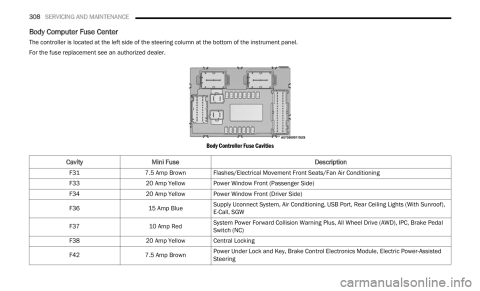
Body Computer Fuse Center
The controller is located at the left side of the steering column at the bottom of the instrument panel.
For the fuse replacement see an authorized dealer.
Body Controller Fuse Cavities
CavityMini Fuse Description
F317.5 Amp BrownFlashes/Electrical Movement Front Seats/Fan Air Conditioning
F33 20 Amp YellowPower Window Front (Passenger Side)
F34 20 Amp YellowPower Window Front (Driver Side)
F36 15 Amp BlueSupply Uconnect System, Air Conditioning, USB Port, Rear Ceiling Lights (With Sunroof),
E-Call
, SGW
F37 10 Amp RedSystem Power Forward Collision Warning Plus, All Wheel Drive (AWD), IPC, Brake Pedal
Switc
h
(NC)
F38 20 Amp YellowCentral Locking
F42 7.5 Amp BrownPower Under Lock and Key, Brake Control Electronics Module, Electric Power-Assisted
Steer
i
ng
Page 311 of 364
SERVICING AND MAINTENANCE 309
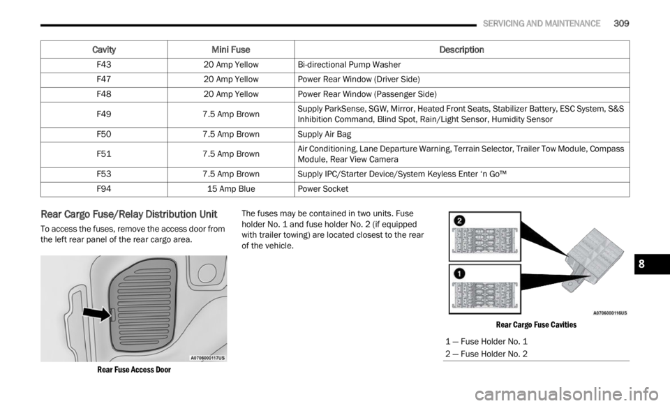
Rear Cargo Fuse/Relay Distribution Unit
To access the fuses, remove the access door from
the left rear panel of the rear cargo area.
Rear Fuse Access Door
The fuses may be contained in two units. Fuse
holder
No. 1 and fuse holder No. 2 (if equipped
with trailer towing) are located closest to the rear
of the vehicle.
Rear Cargo Fuse Cavities
F43
20 Amp YellowBi-directional Pump Washer
F47 20 Amp YellowPower Rear Window (Driver Side)
F48 20 Amp YellowPower Rear Window (Passenger Side)
F49 7.5 Amp BrownSupply ParkSense, SGW, Mirror, Heated Front Seats, Stabilizer Battery, ESC System, S&S
Inhib
i
tion Command, Blind Spot, Rain/Light Sensor, Humidity Sensor
F50 7.5 Amp BrownSupply Air Bag
F51 7.5 Amp BrownAir Conditioning, Lane Departure Warning, Terrain Selector, Trailer Tow Module, Compass
Module
,
Rear View Camera
F53 7.5 Amp BrownSupply IPC/Starter Device/System Keyless Enter ‘n Go™
F94 15 Amp BluePower Socket
Cavity Mini Fuse Description
1 — Fuse Holder No. 1
2 — Fuse Holder No. 2
8
Page 315 of 364
SERVICING AND MAINTENANCE 313
Replacing Exterior Bulbs
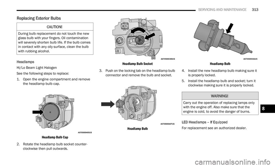
Headlamps
Hi/Lo Beam Light Halogen
See the following steps to replace:
1. O
pen the engine compartment and remove
the he a
dlamp bulb cap.
Headlamp Bulb Cap
2. Rotate the headlamp bulb socket counter -
clock w
ise then pull outwards.
Headlamp Bulb Socket
3. P ush on the locking tab on the headlamp bulb
conne c
tor and remove the bulb and socket.
Headlamp Bulb Headlamp Bulb
4. Install the new headlamp bulb making sure it is pr operly locked.
5. Install the headlamp bulb and socket; turn it clockw
ise making sure it is properly locked.
LED Headlamps – If Equipped
For replacement see an authorized dealer.
CAUTION!
During bulb replacement do not touch the new
glass bulb with your fingers. Oil contamination
will severely shorten bulb life. If the bulb comes
in contact with any oily surface, clean the bulb
with rubbing alcohol.
WARNING!
Carry out the operation of replacing lamps only
with the engine off. Also make sure that the
engine is cold, to avoid the danger of burns.
8
Page 323 of 364
SERVICING AND MAINTENANCE 321
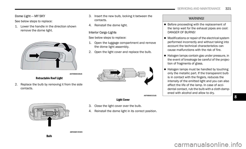
Dome Light — MY SKY
See below steps to replace:
1. L
ower the handle in the direction shown
remove
the dome light.
Retractable Roof Light
2. Replace the bulb by removing it from the side conta c
ts.
Bulb
3. I
nsert the new bulb, locking it between the
c on t
a c
ts.
4. Reinstall the dome light.
Inter
ior Cargo Lights
See below steps to replace:
1. Open the luggage compartment and remove the d o
me light assembly.
2. Open the light cover and replace the bulb.
Light
Cover
3. Close the light cover over the bulb.
4. R ein
stall the dome light in its correct position.
WARNING!
Before proceeding with the replacement of
the lamp wait for the exhaust pipes are cool:
DANGER OF BURNS!
Modifications or repair of the electrical system
performed incorrectly and without taking into
account the technical characteristics can
cause malfunctions with the risk of fire.
Halogen lamps contain gas under pressure, in
the event of breakage be careful of the projec -
tion of fragments of glass.
Halogen lamps must be handled by touching
only the metallic part. If the transparent bulb
is in contact with the fingers, reduces the
intensity of the emitted light and you can also
affect the life of the lamp. In case of acci -
dental contact, rub the bulb with a cloth damp -
ened with alcohol and allow to dry.
8
Page 334 of 364
332 SERVICING AND MAINTENANCE
Keep dismounted tires in a cool, dry place with as
little exposure to light as possible. Protect tires
from contact with oil, grease, and gasoline.
Replacement Tires
The tires on your new vehicle provide a balance of
many characteristics. They should be inspected
regularly for wear and correct cold tire inflation
pressures. The manufacturer strongly
recommends that you use tires equivalent to the
originals in size, quality and performance when
replacement is needed
Ú page 331. Refer to the
Tire and Loading Information placard or the
Vehic l
e Certification Label for the size designation
of your tire. The Load Index and Speed Symbol for
your tire will be found on the original equipment
tire sidewall.
See the Tire Sizing Chart example for more
inform a
tion relating to the Load Index and Speed
Symbol of a tire Ú page 323.
It is recommended to replace the two front tires or
two re a
r tires as a pair. Replacing just one tire can
seriously affect your vehicle’s handling. If you ever
replace a wheel, make sure that the wheel’s
specifications match those of the original wheels.
It is recommended you contact an authorized tire
deale r
or original equipment dealer with any
questions you may have on tire specifications or capability. Failure to use equivalent replacement
tires may adversely affect the safety, handling, and
ride of your vehicle.
TIRE TYPES
All Season Tires — If Equipped
All Season tires provide traction for all seasons
(Spring, Summer, Autumn, and Winter). Traction
levels may vary between different all season tires.
All season tires can be identified by the M+S, M&S,
M/S or MS designation on the tire sidewall. Use all
season tires only in sets of four; failure to do so
may adversely affect the safety and handling of
your vehicle.
Summer Or Three Season Tires —
If Equipped
Summer tires provide traction in both wet and dry
conditions, and are not intended to be driven in
snow or on ice. If your vehicle is equipped with
Summer tires, be aware these tires are not
designed for Winter or cold driving conditions.
Install Winter tires on your vehicle when ambient
temperatures are less than 40°F (5°C) or if roads
are covered with ice or snow. For more
information, contact an authorized dealer.
WARNING!
Do not use a tire, wheel size, load rating, or
speed rating other than that specified for your
vehicle. Some combinations of unapproved
tires and wheels may change suspension
dimensions and performance characteristics,
resulting in changes to steering, handling, and
braking of your vehicle. This can cause unpre -
dictable handling and stress to steering and
suspe n
sion components. You could lose
control and have a collision resulting in
serious injury or death. Use only the tire and
wheel sizes with load ratings approved for
your vehicle.
Never use a tire with a smaller load index or
capacity, other than what was originally
equipped on your vehicle. Using a tire with a
smaller load index could result in tire over -
loading and failure. You could lose control and
h ave a
collision.
Failure to equip your vehicle with tires having
adequate speed capability can result in
sudden tire failure and loss of vehicle control.
CAUTION!
Replacing original tires with tires of a different
size may result in false speedometer and
odometer readings.
Page 343 of 364
341
TECHNICAL SPECIFICATIONS
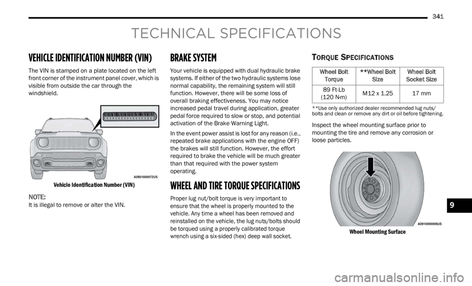
VEHICLE IDENTIFICATION NUMBER (VIN)
The VIN is stamped on a plate located on the left
front corner of the instrument panel cover, which is
visible from outside the car through the
windshield.
Vehicle Identification Number (VIN)
NOTE:
It is illegal to remove or alter the VIN.
BRAKE SYSTEM
Your vehicle is equipped with dual hydraulic brake
systems. If either of the two hydraulic systems lose
normal capability, the remaining system will still
function. However, there will be some loss of
overall braking effectiveness. You may notice
increased pedal travel during application, greater
pedal force required to slow or stop, and potential
activation of the Brake Warning Light.
In the event power assist is lost for any reason (i.e.,
repea t
ed brake applications with the engine OFF)
the brakes will still function. However, the effort
required to brake the vehicle will be much greater
than that required with the power system
operating.
WHEEL AND TIRE TORQUE SPECIFICATIONS
Proper lug nut/bolt torque is very important to
ensure that the wheel is properly mounted to the
vehicle. Any time a wheel has been removed and
reinstalled on the vehicle, the lug nuts/bolts should
be torqued using a properly calibrated torque
wrench using a six-sided (hex) deep wall socket.
TORQUE SPECIFICATIONS
**Use only authorized dealer recommended lug nuts/
bolts and clean or remove any dirt or oil before tightening.
Inspect the wheel mounting surface prior to
mounting the tire and remove any corrosion or
loose particles.
Wheel Mounting Surface
Wheel Bolt Torque**Wheel Bolt Size Wheel Bolt
Socket Size
89 Ft-Lb
(120 N·
m) M12 x 1.25
17 mm
9
Page 344 of 364
342 TECHNICAL SPECIFICATIONS
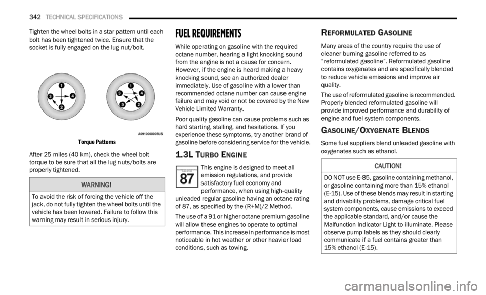
Tighten the wheel bolts in a star pattern until each
bolt has been tightened twice. Ensure that the
socket is fully engaged on the lug nut/bolt.
Torque Patterns
After 25 miles (40 km), check the wheel bolt
torque
to be sure that all the lug nuts/bolts are
properly tightened.
FUEL REQUIREMENTS
While operating on gasoline with the required
octane number, hearing a light knocking sound
from the engine is not a cause for concern.
However, if the engine is heard making a heavy
knocking sound, see an authorized dealer
immediately. Use of gasoline with a lower than
recommended octane number can cause engine
failure and may void or not be covered by the New
Vehicle Limited Warranty.
Poor quality gasoline can cause problems such as
hard s
tarting, stalling, and hesitations. If you
experience these symptoms, try another brand of
gasoline before considering service for the vehicle.
1.3L TURBO ENGINE
This engine is designed to meet all
emission regulations, and provide
s a t
is
f
actory fuel economy and
performance, when using high-quality
unleaded regular gasoline having an octane rating
of 87, as specified by the (R+M)/2 Method.
The use of a 91 or higher octane premium gasoline
will a
llow these engines to operate to optimal
performance. This increase in performance is most
noticeable in hot weather or other heavier load
conditions, such as towing.
REFORMULATED GASOLINE
Many areas of the country require the use of
cleaner burning gasoline referred to as
“reformulated gasoline”. Reformulated gasoline
contains oxygenates and are specifically blended
to reduce vehicle emissions and improve air
quality.
The use of reformulated gasoline is recommended.
Proper l
y blended reformulated gasoline will
provide improved performance and durability of
engine and fuel system components.
GASOLINE/OXYGENATE BLENDS
Some fuel suppliers blend unleaded gasoline with
oxygenates such as ethanol.
WARNING!
To avoid the risk of forcing the vehicle off the
jack, do not fully tighten the wheel bolts until the
vehicle has been lowered. Failure to follow this
warning may result in serious injury.
CAUTION!
DO NOT use E-85, gasoline containing methanol,
or gasoline containing more than 15% ethanol
(E-15). Use of these blends may result in starting
and drivability problems, damage critical fuel
system components, cause emissions to exceed
the applicable standard, and/or cause the
Malfunction Indicator Light to illuminate. Please
observe pump labels as they should clearly
communicate if a fuel contains greater than
15% ethanol (E-15).