brake sensor JEEP RENEGADE 2023 Owners Manual
[x] Cancel search | Manufacturer: JEEP, Model Year: 2023, Model line: RENEGADE, Model: JEEP RENEGADE 2023Pages: 364, PDF Size: 18.65 MB
Page 12 of 364
10
VEHICLE MODIFICATIONS/ALTERATIONS
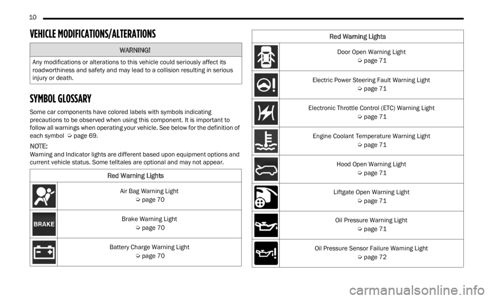
SYMBOL GLOSSARY
Some car components have colored labels with symbols indicating
precautions to be observed when using this component. It is important to
follow all warnings when operating your vehicle. See below for the definition of
each symbol
Ú page 69.
NOTE:
Warning and Indicator lights are different based upon equipment options and
curre n
t vehicle status. Some telltales are optional and may not appear.
WARNING!
Any modifications or alterations to this vehicle could seriously affect its
roadworthiness and safety and may lead to a collision resulting in serious
injury or death.
Red Warning Lights
Air Bag Warning Light
Ú page 70
Brake Warning Light Ú page 70
Battery Charge Warning Light Ú page 70
Door Open Warning Light
Ú page 71
Electric Power Steering Fault Warning Light Ú page 71
Electronic Throttle Control (ETC) Warning Light Ú page 71
Engine Coolant Temperature Warning Light Ú page 71
Hood Open Warning Light Ú page 71
Liftgate Open Warning Light Ú page 71
Oil Pressure Warning Light Ú page 71
Oil Pressure Sensor Failure Warning Light Ú page 72
Red Warning Lights
Page 74 of 364
72 GETTING TO KNOW YOUR INSTRUMENT PANEL
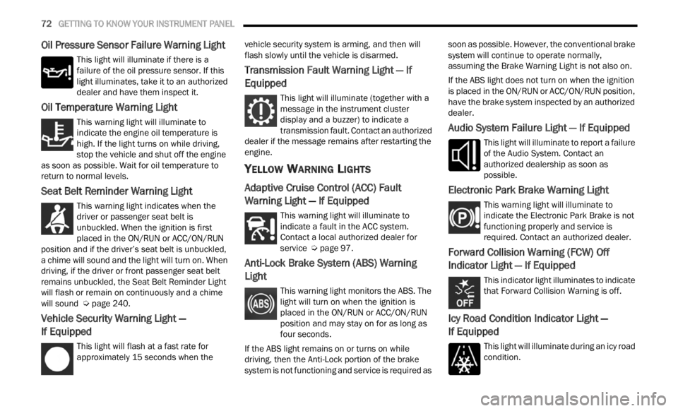
Oil Pressure Sensor Failure Warning Light
This light will illuminate if there is a
failure of the oil pressure sensor. If this
light
illuminates, take it to an authorized
dealer and have them inspect it.
Oil Temperature Warning Light
This warning light will illuminate to
indicate the engine oil temperature is
high.
If the light turns on while driving,
stop the vehicle and shut off the engine
as soon as possible. Wait for oil temperature to
return to normal levels.
Seat Belt Reminder Warning Light
This warning light indicates when the
driver or passenger seat belt is
unbuc k
led. When the ignition is first
placed in the ON/RUN or ACC/ON/RUN
position and if the driver’s seat belt is unbuckled,
a chime will sound and the light will turn on. When
driving, if the driver or front passenger seat belt
remains unbuckled, the Seat Belt Reminder Light
will flash or remain on continuously and a chime
will sound Ú page 240.
Vehicle Security Warning Light —
If Equipped
This light will flash at a fast rate for
approximately 15 seconds when the v
e h
ic
l e security system is arming, and then will
flash slowly until the vehicle is disarmed.
Transmission Fault Warning Light — If
Equipped
This light will illuminate (together with a
message in the instrument cluster
d is
p l
a
y and a buzzer) to indicate a
transmission fault. Contact an authorized
dealer if the message remains after restarting the
engine.
YELLOW WARNING LIGHTS
Adaptive Cruise Control (ACC) Fault
Warning Light — If Equipped
This warning light will illuminate to
indicate a fault in the ACC system.
C on t
a c
t
a local authorized dealer for
service Ú page 97.
Anti-Lock Brake System (ABS) Warning
Light
This warning light monitors the ABS. The
light will turn on when the ignition is
p
la
ce
d
in the ON/RUN or ACC/ON/RUN
position and may stay on for as long as
four seconds.
If the ABS light remains on or turns on while
drivin
g, then the Anti-Lock portion of the brake
system is not functioning and service is required as soon as possible. However, the conventional brake
system will continue to operate normally,
assuming the Brake Warning Light is not also on.
If the ABS light does not turn on when the ignition
is pl
a
ced in the ON/RUN or ACC/ON/RUN position,
have the brake system inspected by an authorized
dealer.
Audio System Failure Light — If Equipped
This light will illuminate to report a failure
of the Audio System. Contact an
author i
zed dealership as soon as
possible.
Electronic Park Brake Warning Light
This warning light will illuminate to
indicate the Electronic Park Brake is not
funct i
oning properly and service is
required. Contact an authorized dealer.
Forward Collision Warning (FCW) Off
Indicator Light — If Equipped
This indicator light illuminates to indicate
that Forward Collision Warning is off.
Icy Road Condition Indicator Light —
If Equipped
This light will illuminate during an icy road
condition.
Page 99 of 364
STARTING AND OPERATING 97
(Continued)
Resume Speed
To resume a previously set speed, push the RES
button and release. Resume can be used at any
speed above 20 mph (32 km/h).
Deactivation
A soft tap on the brake pedal, pushing the CANC
button, or normal brake pressure while slowing the
vehicle will deactivate the Cruise Control without
erasing the set speed from memory.
Pushing the on/off button or placing the ignition in
the OF
F position erases the set speed from
memory.
ADAPTIVE CRUISE CONTROL (ACC)
Adaptive Cruise Control (ACC) increases the driving
convenience provided by Cruise Control while
traveling on highways and major roadways.
However, it is not a safety system and not designed
to prevent collisions. The Cruise Control function
performs differently if your vehicle is not equipped
with ACC Ú page 95.
ACC will allow you to keep Cruise Control engaged
in li g
ht to moderate traffic conditions without the
constant need to reset your speed. ACC utilizes a
radar sensor and a forward facing camera
designed to detect a vehicle directly ahead of you
to maintain a set speed.
NOTE:
If the ACC sensor detects a vehicle ahead, ACC
will apply limited braking or accelerate (not to
exceed the original set speed) automatically to
maintain a preset following distance, while
matching the speed of the vehicle ahead.
Any chassis/suspension or tire size modifica -
tions to the vehicle will affect the performance
of t
h e
Adaptive Cruise Control and Forward Colli -
sion Warning system.
Fixed Speed Cruise Control (ACC not enabled)
will not detect vehicles directly ahead of you.
Always be aware of the feature selected
Ú page 349.
WARNING!
Adaptive Cruise Control (ACC) is a convenience
system. It is not a substitute for active driver
involvement. It is always the driver’s responsi
-
bility to be attentive of road, traffic, and weather
condi t
ions, vehicle speed, distance to the
vehicle ahead and, most importantly, brake
operation to ensure safe operation of the
vehicle under all road conditions. Your
complete attention is always required while
driving to maintain safe control of your vehicle.
Failure to follow these warnings can result in a
collision and death or serious personal injury.
The ACC system:
Does not react to pedestrians, oncoming
vehicles, and stationary objects (e.g., a
stopped vehicle in a traffic jam or a
disabled vehicle).
Cannot take street, traffic, and weather
conditions into account, and may be
limited upon adverse sight distance condi -
tions.
Does not always fully recognize complex
driving conditions, which can result in
wrong or missing distance warnings.
You should turn the ACC system off:
When driving in fog, heavy rain, heavy snow,
sleet, heavy traffic, and complex driving situa -
tions (i.e., in highway construction zones).
When entering a turn lane or highway
off-ramp; when driving on roads that are
winding, icy, snow-covered, slippery, or have
steep uphill or downhill slopes.
When towing a trailer up or down steep slopes.
When circumstances do not allow safe driving
at a constant speed.
WARNING!
4
Page 103 of 364
STARTING AND OPERATING 101
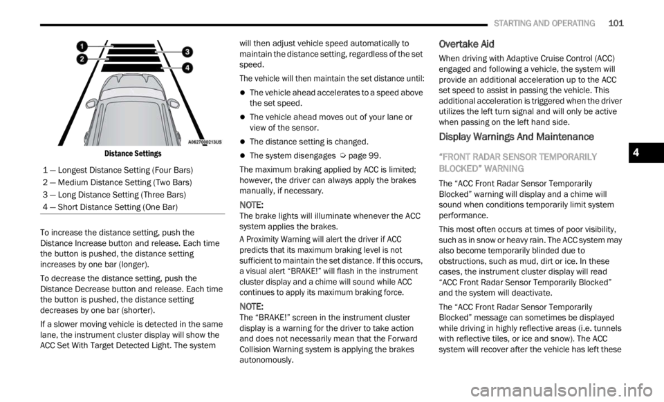
Distance Settings
To increase the distance setting, push the
Distan
ce Increase button and release. Each time
the button is pushed, the distance setting
increases by one bar (longer).
To decrease the distance setting, push the
Distan
ce Decrease button and release. Each time
the button is pushed, the distance setting
decreases by one bar (shorter).
If a slower moving vehicle is detected in the same
lane,
the instrument cluster display will show the
ACC Set With Target Detected Light. The system will then adjust vehicle speed automatically to
maintain the distance setting, regardless of the set
speed.
The vehicle will then maintain the set distance until:
The vehicle ahead accelerates to a speed above
the set speed.
The vehicle ahead moves out of your lane or
view of the sensor.
The distance setting is changed.
The system disengages
Ú page 99.
The maximum braking applied by ACC is limited;
howeve r
, the driver can always apply the brakes
manually, if necessary.
NOTE:
The brake lights will illuminate whenever the ACC
syste m
applies the brakes.
A Proximity Warning will alert the driver if ACC
predic
ts that its maximum braking level is not
sufficient to maintain the set distance. If this occurs,
a visual alert “BRAKE!” will flash in the instrument
cluster display and a chime will sound while ACC
continues to apply its maximum braking force.
NOTE:
The “BRAKE!” screen in the instrument cluster
displ a
y is a warning for the driver to take action
and does not necessarily mean that the Forward
Collision Warning system is applying the brakes
autonomously.
Overtake Aid
When driving with Adaptive Cruise Control (ACC)
engaged and following a vehicle, the system will
provide an additional acceleration up to the ACC
set speed to assist in passing the vehicle. This
additional acceleration is triggered when the driver
utilizes the left turn signal and will only be active
when passing on the left hand side.
Display Warnings And Maintenance
“FRONT RADAR SENSOR TEMPORARILY
BLOCKED” WARNING
The “ACC Front Radar Sensor Temporarily
Blocked” warning will display and a chime will
sound when conditions temporarily limit system
performance.
This most often occurs at times of poor visibility,
such a
s in snow or heavy rain. The ACC system may
also become temporarily blinded due to
obstructions, such as mud, dirt or ice. In these
cases, the instrument cluster display will read
“ACC Front Radar Sensor Temporarily Blocked”
and the system will deactivate.
The “ACC Front Radar Sensor Temporarily
Blocke d
” message can sometimes be displayed
while driving in highly reflective areas (i.e. tunnels
with reflective tiles, or ice and snow). The ACC
system will recover after the vehicle has left these
1 — Longest Distance Setting (Four Bars)
2 — Medium Distance Setting (Two Bars)
3 — Long Distance Setting (Three Bars)
4 — Short Distance Setting (One Bar)
4
Page 113 of 364
STARTING AND OPERATING 111
Clean the ParkSense sensors regularly, taking
care not to scratch or damage them. The
sensors must not be covered with ice, snow,
slush, mud, dirt or debris. Failure to do so can
result in the system not working properly. The
ParkSense system might not detect an obstacle
behind or in front of the fascia/bumper, or it
could provide a false indication that an obstacle
is behind or in front of the fascia/bumper.
The presence of a tow hook without a trailer may
interfere with the correct operation of the
parking sensors. Before using the ParkSense
system, it is recommended to remove the
removable tow hook ball assembly and any
attachments from the vehicle when it is not
used for towing operations. If you wish to leave
the tow hook fitted when not towing a trailer,
contact your authorized dealer for the Park
-
Sense system operations update because the
tow hook
could be detected as an obstacle by
the sensors.
PARKSENSE ACTIVE PARK ASSIST SYSTEM —
IF EQUIPPED
The ParkSense Active Park Assist system is
intended to assist the driver during parallel,
perpendicular, and parallel park exit maneuvers by
identifying a proper parking space, providing
audible/visual instructions, and controlling the
steering wheel. The ParkSense Active Park Assist
system is defined as “semi-automatic” since the
driver maintains control of the accelerator, gear
selector and brakes. Depending on the driver's
parking maneuver selection, the ParkSense Active
Park Assist system is capable of maneuvering a
WARNING!
Drivers must be careful when backing up even
when using ParkSense. Always check carefully
behind your vehicle, look behind you, and be
sure to check for pedestrians, animals, other
vehicles, obstructions, and blind spots before
backing up. You are responsible for safety and
must continue to pay attention to your
surroundings. Failure to do so can result in
serious injury or death.
Before using ParkSense, it is strongly recom -
mended that the ball mount and hitch ball
assem b
ly be disconnected from the vehicle
when the vehicle is not used for towing.
Failure to do so can result in injury or damage
to vehicles or obstacles because the hitch ball
will be much closer to the obstacle than the
rear fascia when the vehicle sounds the
continuous tone. Also, the sensors could
detect the ball mount and hitch ball assembly,
depending on its size and shape, giving a false
indication that an obstacle is behind the
vehicle.
CAUTION!
ParkSense is only a parking aid and it is
unable to recognize every obstacle, including
small obstacles. Parking curbs might be
temporarily detected or not detected at all.
Obstacles located above or below the sensors
will not be detected when they are in close
proximity.
The vehicle must be driven slowly when using
ParkSense in order to be able to stop in time
when an obstacle is detected. It is recom -
mended that the driver looks over his/her
should e
r when using ParkSense.
4
Page 114 of 364

112 STARTING AND OPERATING
vehicle into a parallel or a perpendicular parking
space on either side (i.e., driver side or passenger
side), as well as exiting a parallel parking space.
NOTE:
The driver is always responsible for controlling
the vehicle, responsible for any surrounding
objects, and must intervene as required.
The system is designed to assist the driver and
not to substitute the driver.
During a semi-automatic maneuver, if the driver
touches the steering wheel after being
instructed to remove their hands from the
steering wheel, the system will cancel, and the
driver will be required to manually complete the
parking maneuver.
The system may not work in all conditions (e.g.
environmental conditions such as heavy rain,
snow, etc., or if searching for a parking space
that has surfaces that will absorb the ultrasonic
sensor waves).
ENABLING AND DISABLING THE
P
ARKSENSE ACTIVE PARK ASSIST
S
YSTEM
The ParkSense Active Park Assist system
can be enabled and disabled with the
ParkS e
nse Active Park Assist switch,
located on the switch panel below the
Uconnect display. To enable or disable the ParkSense Active Park
Assis
t
system, push the ParkSense Active Park
Assist switch once (LED turns on). Pushing the
switch a second time will disable the system (LED
turns off).
The ParkSense Active Park Assist system will turn off
autom a
tically for any of the following conditions:
Parking maneuver is complete
Vehicle speed is greater than 18 mph (30 km/h)
when se
arching for a parking space
Vehicle speed is greater than 5 mph (7 km/h)
during
active steering guidance into the parking
space
Steering wheel is touched during active steering
guidance into the parking space
ParkSense Front/Rear Park Assist switch is
pushed
Driver's door is opened
Rear liftgate is opened
Electronic Stability Control/Anti-Lock Brake
System intervention
The ParkSense Active Park Assist system will allow
a maxi
mum number of shifts between DRIVE and
REVERSE. If the maneuver cannot be completed
within the maximum amount of shifts, the system
will cancel and the instrument cluster display will
instruct the driver to complete the maneuver
manually. The ParkSense Active Park Assist system will only
operat
e
and search for a parking space when the
following conditions are present:
Gear selector is in DRIVE.
Ignition is in the RUN position.
ParkSense Active Park Assist switch is acti -
vated.
Driver's door is closed.
Rear liftgate is closed.
Vehicle speed is less than 15 mph (25 km/h).
NOTE:
If the vehicle is driven above approximately
15 mph
(25 km/h), the instrument cluster display
will i
nstruct the driver to slow down. If the vehicle
is driven above approximately 18 mph (30 km/h),
the sy
stem will cancel. The driver must then reac -
tivate the system by pushing the ParkSense Active
Park A
ssist switch.
The outer surface and the underside of the front
and rear fascias/bumpers are clean and clear
of snow, ice, mud, dirt or other obstruction.
When pushed, the LED on the ParkSense Active
Park A
ssist switch will blink momentarily, and then
the LED will turn off if any of the above conditions
are not present.
Page 117 of 364
STARTING AND OPERATING 115
(Continued)
EXITING THE PARKING SPACE
NOTE:
The function does not work for exiting a perpen -
dicular parking space, but only exiting parallel
p arki n
g spaces.
Activation
To activate this function, push the ParkSense
Activ e
Park Assist switch and then use the steering
wheel arrow buttons to select the Parallel Park Exit
feature. After the selection, the system activates
and instructs the driver through the instrument
cluster display about the operations that have to
be carried out to perform the maneuver correctly. Selection Of The Maneuver Side
Use the right and left arrow buttons on the steering
wheel
to select between parallel or perpendicular
parking mode. Then use the direction indicators
(turn signals) to choose the direction that you want
to perform the maneuver.
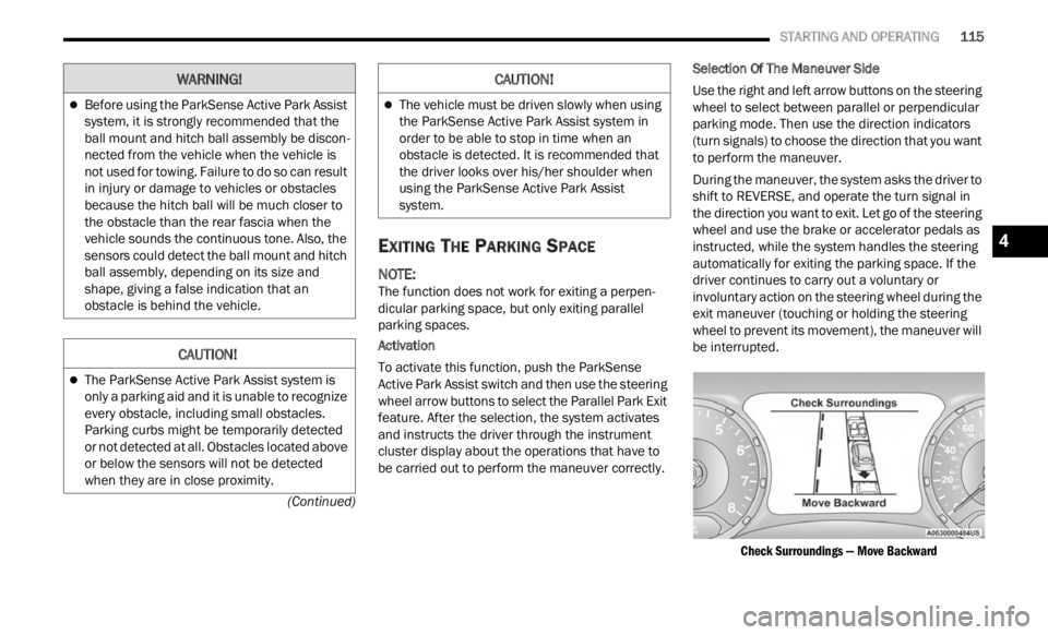
During the maneuver, the system asks the driver to
shift
to REVERSE, and operate the turn signal in
the direction you want to exit. Let go of the steering
wheel and use the brake or accelerator pedals as
instructed, while the system handles the steering
automatically for exiting the parking space. If the
driver continues to carry out a voluntary or
involuntary action on the steering wheel during the
exit maneuver (touching or holding the steering
wheel to prevent its movement), the maneuver will
be interrupted.
Check Surroundings — Move Backward
Before using the ParkSense Active Park Assist
system, it is strongly recommended that the
ball mount and hitch ball assembly be discon -
nected from the vehicle when the vehicle is
not us e
d for towing. Failure to do so can result
in injury or damage to vehicles or obstacles
because the hitch ball will be much closer to
the obstacle than the rear fascia when the
vehicle sounds the continuous tone. Also, the
sensors could detect the ball mount and hitch
ball assembly, depending on its size and
shape, giving a false indication that an
obstacle is behind the vehicle.
CAUTION!
The ParkSense Active Park Assist system is
only a parking aid and it is unable to recognize
every obstacle, including small obstacles.
Parking curbs might be temporarily detected
or not detected at all. Obstacles located above
or below the sensors will not be detected
when they are in close proximity.
WARNING!
The vehicle must be driven slowly when using
the ParkSense Active Park Assist system in
order to be able to stop in time when an
obstacle is detected. It is recommended that
the driver looks over his/her shoulder when
using the ParkSense Active Park Assist
system.
CAUTION!
4
Page 225 of 364

SAFETY 223
Electronic Stability Control (ESC)
ESC enhances directional control and stability of
the vehicle under various driving conditions. ESC
corrects for oversteering or understeering of the
vehicle by applying the brake of the appropriate
wheel(s) to counteract the above conditions.
Engine power may also be reduced to help the
vehicle maintain the desired path.
Oversteer — when the vehicle is turning more
than appropriate for the steering wheel position.
Understeer — when the vehicle is turning less
than appropriate for the steering wheel position.
ESC uses sensors in the vehicle to determine the
vehicl
e path intended by the driver and compares
it to the actual path of the vehicle. When the actual
path does not match the intended path, ESC
applies the brake of the appropriate wheel to
assist in counteracting the oversteer or understeer
condition.
The ESC Activation/Malfunction Indicator Light
locate d
in the instrument cluster will start to flash
as soon as the ESC system becomes active. The
ESC Activation/Malfunction Indicator Light also
flashes when the TCS is active. If the ESC
Activation/Malfunction Indicator Light begins to
flash during acceleration, ease up on the
accelerator and apply as little throttle as possible.
Be sure to adapt your speed and driving to the
prevailing road conditions.
WARNING!
Many factors, such as vehicle loading, road
conditions, and driving conditions, influence the
chance that wheel lift or rollover may occur.
Electronic Roll Mitigation (ERM) cannot prevent
all wheel lift or rollovers, especially those that
involve leaving the roadway or striking objects or
other vehicles. The capabilities of an
ERM-equipped vehicle must never be exploited
in a reckless or dangerous manner, which could
jeopardize the user's safety or the safety of
others.
WARNING!
Electronic Stability Control (ESC) cannot
prevent the natural laws of physics from acting
on the vehicle, nor can it increase the traction
afforded by prevailing road conditions. ESC
cannot prevent accidents, including those
resulting from excessive speed in turns, driving
on very slippery surfaces, or hydroplaning. ESC
also cannot prevent accidents resulting from
loss of vehicle control due to inappropriate
driver input for the conditions. Only a safe,
attentive, and skillful driver can prevent acci -
dents. The capabilities of an ESC equipped
vehic l
e must never be exploited in a reckless or
dangerous manner which could jeopardize the
user’s safety or the safety of others.
Vehicle modifications, or failure to properly
maintain your vehicle, may change the handling
characteristics of your vehicle, and may nega -
tively affect the performance of the ESC system.
Chang e
s to the steering system, suspension,
braking system, tire type and size or wheel size
may adversely affect ESC performance. Improp -
erly inflated and unevenly worn tires may also
d egrad
e ESC performance. Any vehicle modifi-
cation or poor vehicle maintenance that
r educe
s the effectiveness of the ESC system
can increase the risk of loss of vehicle control,
vehicle rollover, personal injury and death.
6
Page 229 of 364
SAFETY 227
Hill Start Assist (HSA)
HSA is designed to help the driver accelerate the
vehicle from a complete stop while on an incline. If
the driver releases the brake while stopped on an
incline, HSA will continue to hold the brake
pressure for a short period. If the driver does not
apply the throttle before this time expires, the
system will release brake pressure and the vehicle
will roll down the hill as normal. The system will
release brake pressure in proportion to amount of
throttle applied.
The following conditions must be met in order for
HSA to a
ctivate:
The vehicle must be stopped.
The vehicle must be on a 5% (approximate)
grade or greater hill.
The gear selection must match vehicle uphill
direction (i.e., vehicle facing uphill is in forward
gear; vehicle backing uphill is in REVERSE gear).
For vehicles equipped with an automatic trans -
mission, the HSA will work in REVERSE gear and all f
or ward gears. The system will not activate if
the transmission is in PARK.
Disabling And Enabling HSA
This feature can be turned on or turned off. To
chang e
the current setting, see Ú page 64.
Traction Control System (TCS)
TCS monitors the amount of wheel spin of each of
the driven wheels. If wheel spin is detected, brake
pressure is applied to the slipping wheel(s) and
engine power is reduced to provide enhanced
acceleration and stability. A feature of the TCS,
Brake Limited Differential (BLD) functions similarly to a limited slip differential and controls the wheel
spin across a driven axle. If one wheel on a driven
axle is spinning faster than the other, the system
will apply the brake of the spinning wheel. This will
allow more engine torque to be applied to the
wheel that is not spinning. This feature remains
active even if TCS and Electronic Stability Control
(ESC) are in the “Partial Off” mode or the “Full Off”
modes. For further information, see
Ú page 223.
Trailer Sway Control (TSC) — If Equipped
TSC uses sensors in the vehicle to recognize an
excessively swaying trailer and will take the
appropriate actions to attempt to stop the sway.
The system may reduce engine power and apply
the brake of the appropriate wheel(s) to counteract
the sway of the trailer.
NOTE:
TSC cannot stop all trailers from swaying. Always
use c a
ution when towing a trailer and follow the
trailer tongue weight recommendations. For
further information, see Ú page 124. When TSC is
functioning, the ESC Activation/Malfunction Indi -
cator Light will flash, the engine power may be
r educ e
d and you may feel the brakes being applied
to individual wheels to attempt to stop the trailer
from swaying. TSC is disabled when the ESC
system is in the “Partial Off” mode.
WARNING!
HDC is only intended to assist the driver in
controlling vehicle speed when descending hills.
The driver must remain attentive to the driving
conditions and is responsible for maintaining a
safe vehicle speed.WARNING!
There may be situations where the Hill Start
Assist (HSA) will not activate and slight rolling
may occur, such as on minor hills or with a
loaded vehicle, or while pulling a trailer. HSA is
not a substitute for active driving involvement. It
is always the driver’s responsibility to be
attentive to distance to other vehicles, people,
and objects, and most importantly brake
operation to ensure safe operation of the vehicle
under all road conditions. Your complete
attention is always required while driving to
maintain safe control of your vehicle. Failure to
follow these warnings can result in a collision or
serious personal injury.
6
Page 234 of 364
232 SAFETY
NOTE:
Vehicle must be taken to the nearest authorized
deale r
for service.
FORWARD COLLISION WARNING (FCW)
W
ITH MITIGATION OPERATION —
I
F EQUIPPED
FCW with Mitigation provides the driver with
audible warnings (through the radio), visual
warnings (within the instrument cluster display),
and may apply a brake jerk to warn the driver when
it detects a potential frontal collision. The warnings
and limited braking are intended to provide the
driver with enough time to react, avoid or mitigate
the potential collision.
NOTE:
FCW monitors the information from the forward
looking sensors as well as the Electronic Brake
Controller (EBC), to calculate the probability of a
forward collision. When the system determines
that a forward collision is probable, the driver
will be provided with audible and visual warn -
ings and may provide a brake jerk warning.
If the driver does not take action based upon
these progressive warnings, then the system
will provide a limited level of active braking to
help slow the vehicle and mitigate the potential
forward collision. If the driver reacts to the warn -
ings by braking and the system determines that the d
r
iver intends to avoid the collision by
braking but has not applied sufficient brake
force, the system will compensate and provide
additional brake force as required.
Vehicles With A Manual Transmission : Afte
r the
end of the intervention of automatic braking, the
engine could stall, unless the driver can press the
clutch pedal.
Vehicles With Automatic Transmission : Afte
r the
end of the intervention of automatic braking, the
transmission may remain in last gear stored:
therefore the vehicle could lurch forward, once the
brakes release a few seconds later. If the Forward
Collision Warning with Mitigation event stops the
vehicle completely, the system will hold the vehicle
at standstill for two seconds and then release the
brakes.
If a FCW with Mitigation event begins at a speed
below 2
6 mph (42 km/h), the system may provide
the m a
ximum braking possible to mitigate the
potential forward collision. If the Forward Collision
Warning with Mitigation event stops the vehicle
completely, the system will hold the vehicle at
standstill for two seconds and then release the
brakes.
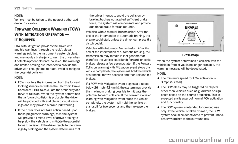
FCW Message
When the system determines a collision with the
vehic l
e in front of you is no longer probable, the
warning message will be deactivated.
NOTE:
The minimum speed for FCW activation is
3 mph (5 km/h).
The FCW alerts may be triggered on objects
other than vehicles such as guardrails or sign
posts based on the course prediction. This is
expected and is a part of normal FCW activation
and functionality.
The FCW system is intended for on-road use
only. If the vehicle is taken off-road, the FCW
system should be deactivated to prevent unnec
-
essary warnings to the surroundings.