display JEEP RENEGADE 2023 Owners Manual
[x] Cancel search | Manufacturer: JEEP, Model Year: 2023, Model line: RENEGADE, Model: JEEP RENEGADE 2023Pages: 364, PDF Size: 18.65 MB
Page 5 of 364
3
WINDSHIELD WIPERS AND WASHERS ............. 41
Windshield Wiper Operation ...... ......................42
Rain Sensing Wipers — If Equipped ..... . .........42
Rear Window Wiper/Washer . ..
..
. .....................43
Windshield Wiper De-Icer — If Equipped ..... . ...43
CLIMATE CONTROLS . ..
. .
. ...................................... 44
Automatic Climate Control Descriptions And
Functions ..........................................................44
Autom a
tic Temperature Control (ATC) ..... . .....47
Climate Voice Commands..... . ..........................47
Operating Tips . ..
..
. ...........................................47
INTERIOR STORAGE AND EQUIPMENT ..... . ......... 48
Storage..............................................................48
USB/A UX Control ..... . ........................................50
Power Outlets ..... . .............................................50
Power Inverter — If Equipped. ..
..
. .....................51
Cigar Lighter — If Equipped. ..
..
. ........................52
Ashtray — If Equipped ..... . ................................52
WINDOWS............................................................... 52
Power
Window Controls ...... .............................52
Automatic Window Features ..... . .....................53
Reset Auto-Up ..... . .............................................53
Window Lockout Switch . ..
..
. .............................54
Wind Buffeting ..... . ...........................................54
DUAL PANE PANORAMIC POWER SUNROOF
WITH POWER SHADE — IF EQUIPPED ..... .
.......... 54
Opening And Closing The Sunroof...... .............55
Venting Sunroof . ..
..
. ..........................................55
Opening And Closing The Power Sunshade....5 5
P inch Protect Feature . ..
. .
. ................................55
Sunroof Maintenance ..... . ................................56 HOOD ......................................................................56
To Op e
n The Hood...... ......................................56
To Close The Hood ..... . .....................................57
LIFTGATE . ................................................................ 57
U n
loc
k
/Open The Liftgate...... ..........................57
Lock/Close The Liftgate . ..
..
. .............................58
Cargo Area Features ..... . ..................................58
ROOF LUGGAGE RACK — IF EQUIPPED . ..
..
. ........61
GETTING TO KNOW YOUR
INSTRUMENT PANEL
INSTRUMENT CLUSTER .........................................62
Instrument Cluster Descriptions ...... ...............64
INSTRUMENT CLUSTER DISPLAY ..... . .................64
Instrument Cluster Display Location And
Controls.............................................................64
Oil C
hange Reset..... . ........................................65
Instrument Cluster Display Menu Items . ..
..
. ..66
TRIP COMPUTER ..... . ..............................................69
WARNING/INDICATOR LIGHTS AND
MESSAGES ......
........................................................69
Red Warning Lights ...... ....................................70
Yellow Warning Lights ..... . ................................72
Yellow Indicator Lights . ..
..
. ...............................75
Green Indicator Lights . ..
..
. ...............................76
White Indicator Lights ..... . ................................77
Blue Indicator Lights ..... . ..................................77
Gray Indicator Lights . ..
..
. ..................................77 ONBOARD DIAGNOSTIC SYSTEM (OBD II) .....
.
... 77
Onboard Diagnostic System
(OBD II) Cybersecurity ..... .
................................ 78
EMISSIONS INSPECTION AND MAINTENANCE
PROGRAMS ..... .
...................................................... 78
STARTING AND OPERATING
STARTING THE ENGINE ......................................... 80
Tip Start Feature ...... ....................................... 80
If Engine Fails To Start ..... . ..............................80
Cold Weather Operation ..... . ............................ 81
Extended Park Starting . ..
..
. ..............................81
After Starting — Warming Up The Engine ..... . . 81
Stopping The Engine . ..
..
. .................................. 81
Turbocharger “Cool Down” — If Equipped ..... . 82
ENGINE BREAK-IN RECOMMENDATIONS . ..
..
. .... 82
ELECTRIC PARK BRAKE (EPB) ...... ....................... 82
Auto Park Brake ...... ......................................... 84
SafeHold . .......................................................... 84
B r
a k
e
Service Mode..... . ................................... 84
9-SPEED AUTOMATIC TRANSMISSION . ..
..
. ........ 85
Gear Selector...... .............................................. 86
Gear Ranges ..... . ............................................... 87
Transmission Limp Home Mode . ..
..
. ............... 90
Ignition Park Interlock
(Keyless Vehicle) . .....
........................................ 90
Brake Transmission Shift Interlock (BTSI)
System . .............................................................90
Page 6 of 364

4
FOUR-WHEEL DRIVE .............................................. 90
Four-Wheel Drive (4WD) ...... ............................91
SELEC-TERRAIN ..... . ............................................... 92
Mode Selection Guide...... ................................92
ACTIVE GRILLE SHUTTERS — IF EQUIPPED ..... . .. 93
POWER STEERING ...... ........................................... 93
STOP/START SYSTEM ...... ..................................... 93
Autostop Mode ......
...........................................93
Possible Reasons The Engine Does Not
Autostop . ...........................................................94
To Sta
rt The Engine While In Autostop
Mode . ................................................................94
To Man
ually Turn Off The Stop/Start
System . .............................................................95
To Man
ually Turn On The Stop/Start
System . .............................................................95
Syste
m Malfunction ..... . ...................................95
CRUISE CONTROL SYSTEMS — IF EQUIPPED. ..
. .
9 5
Cruise Control ...... ............................................95
Adaptive Cruise Control (ACC) . ..
. .
. ...................97
PARKSENSE FRONT/REAR PARK ASSIST
SYSTEM — IF EQUIPPED ..... .
.............................. 105
ParkSense Sensors ...... ................................. 105
ParkSense Warning Display..... . .................... 105
ParkSense Display . ..
..
. .................................. 105
Enabling And Disabling ParkSense ..... . ........ 108
Service The ParkSense Park Assist System .. 108
C l
eaning The ParkSense System . ..
..
. ........... 108
ParkSense System Usage Precautions ..... . .. 108
Side Distance Warning (SDW) System . ..
. .
. ... 109PARKSENSE ACTIVE PARK ASSIST SYSTEM —
IF EQUIPPED ..... .
.................................................. 111
Enabling And Disabling The ParkSense
Active Park Assist System..... .
....................... 112
Parallel/Perpendicular Parking Space
Assistance Operation . .....
.............................. 113
Exiting The Parking Space ..... . ...................... 115
LANESENSE — IF EQUIPPED . ..
. .
. ....................... 117
LaneSense Operation ...... ............................. 117
Turning LaneSense On Or Off ..... . ................. 117
LaneSense Warning Message . ..
..
. ................ 117
Changing LaneSense Status ..... . .................. 121
REAR BACK UP CAMERA . ..
..
. ............................. 121
REFUELING THE VEHICLE ...... ............................ 122
VEHICLE LOADING ...... ....................................... 123
Certification Label ...... ................................... 123
TRAILER TOWING ..... . .......................................... 124
Common Towing Definitions...... ................... 124
Trailer Hitch Classification ..... . ...................... 125
Trailer Towing Weights (Maximum Trailer
Weight Ratings) . .....
....................................... 126
Trailer And Tongue Weight..... . ...................... 126
Towing Requirements . ..
..
. ............................ 126
Towing Tips ..... . .............................................. 128
RECREATIONAL TOWING . ..
..
. ............................. 129
Towing This Vehicle Behind Another
Vehicle ........................................................... 129
Recr e
ational Towing. ..
..
. ................................ 129 DRIVING TIPS .....
.
................................................. 130
On-Road Driving Tips...... ............................... 130
Off-Road Driving Tips ..... . .............................. 130
MULTIMEDIA
UCONNECT SYSTEMS ......................................... 133
CYBERSECURITY ................................................. 133
UCONNECT SETTINGS ...... ................................... 133
Customer Programmable Features ...... ...... 134
UCONNECT INTRODUCTION..... . .......................... 147
System Overview ...... .................................... 147
Drag & Drop Menu Bar . ..
..
. ........................... 149
Safety And General Information..... . ............. 149
UCONNECT MODES ..... . ....................................... 150
Steering Wheel Audio Controls .................... 150
Radi o Mode ..... . ............................................ 151
Media Mode . ..
. .
. ........................................... 162
Phone Mode ..... . ........................................... 164
ANDROID AUTO™ & APPLE CARPLAY® —
IF EQUIPPED ..... .
................................................... 174
Android Auto™ ...... ........................................ 174
Apple CarPlay® . ..
..
. ....................................... 176
Android Auto™ And Apple CarPlay® Tips
And Tricks . ..................................................... 178
Page 16 of 364
14
GETTING TO KNOW YOUR VEHICLE
KEYS
KEY FOB
Your vehicle is equipped with a key fob which
supports Passive Entry, Remote Keyless Entry
(RKE), Keyless Enter ‘n Go™ (if equipped), Remote
Start (if equipped), and Panic button operation.
The key fob allows you to lock or unlock the doors
and liftgate from distances up to approximately
66
ft (20 m). The key fob does not need to be
pointed
at the vehicle to activate the system. The
key fob also contains an emergency key, which is
stored in the rear of the key fob.
NOTE:
The key fob’s wireless signal may be blocked if the
key f ob
is located next to a mobile phone, laptop,
or other electronic device. This may result in poor
performance.
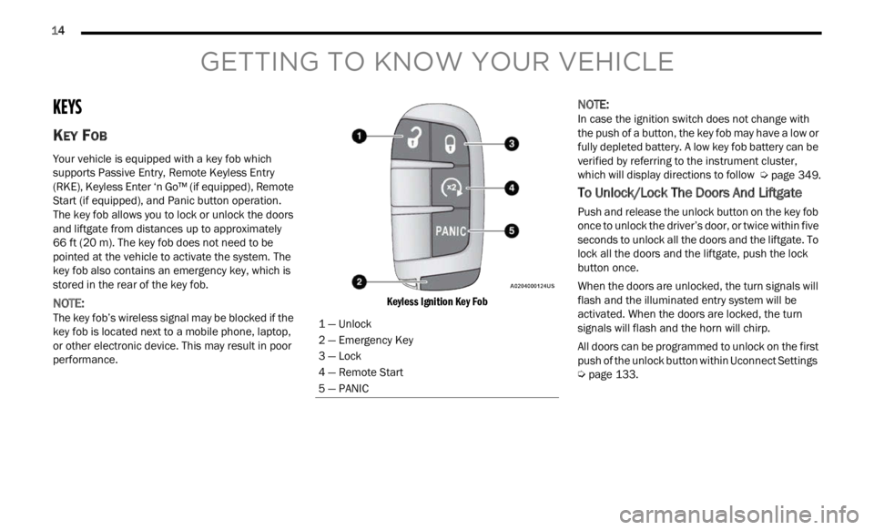
Keyless Ignition Key Fob
NOTE:
In case the ignition switch does not change with
the p u
sh of a button, the key fob may have a low or
fully depleted battery. A low key fob battery can be
verified by referring to the instrument cluster,
which will display directions to follow Ú page 349.
To Unlock/Lock The Doors And Liftgate
Push and release the unlock button on the key fob
once to unlock the driver’s door, or twice within five
seconds to unlock all the doors and the liftgate. To
lock all the doors and the liftgate, push the lock
button once.
When the doors are unlocked, the turn signals will
flash
and the illuminated entry system will be
activated. When the doors are locked, the turn
signals will flash and the horn will chirp.
All doors can be programmed to unlock on the first
push of
the unlock button within Uconnect Settings
Ú page 133.
1 — Unlock
2 — Emergency Key
3 — Lock
4 — Remote Start
5 — PANIC
Page 17 of 364
GETTING TO KNOW YOUR VEHICLE 15
Key Left Vehicle Feature — If Equipped
If a valid key fob is no longer detected inside the
vehicle while the vehicle’s ignition system is in the
ON/RUN or START position, the message “Key Fob
Has Left Vehicle” will be shown in the instrument
cluster display along with an interior chime. An
exterior audible and visual alert will also be
activated to warn the driver.
The vehicle’s horn will rapidly chirp three times
along
with a single flash of the vehicle’s exterior
lights.
NOTE:
The doors have to be open and then closed in
order for the vehicle to check for the presence of
a key fob; the Key Left Vehicle feature will not
activate until all of the doors are closed.
These alerts will not be activated in situations
where the vehicle’s engine is left running with
the key fob inside.
Replacing The Battery In The Key Fob
The replacement battery is one CR2032 battery.
NOTE:
Customers are recommended to use a battery
obtained from Mopar®. Aftermarket coin
battery dimensions may not meet the original
OEM coin battery dimensions.
Perchlorate Material — special handling may
apply. See www.dtsc.ca.gov/hazardouswaste/
perchlorate for further information.
Do not touch the battery terminals that are on
the back housing or the printed circuit board.
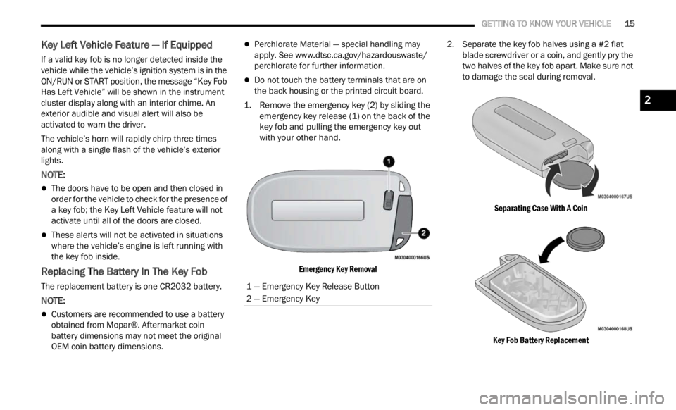
1. Remove the emergency key (2) by sliding the emerge
ncy key release (1) on the back of the
key fob and pulling the emergency key out
with your other hand.
Emergency Key Removal
2. Separate the key fob halves using a #2 flat
blad e
screwdriver or a coin, and gently pry the
two halves of the key fob apart. Make sure not
to damage the seal during removal.
Separating Case With A Coin
Key Fob Battery Replacement
1 — Emergency Key Release Button
2 — Emergency Key
2
Page 21 of 364
GETTING TO KNOW YOUR VEHICLE 19
(Continued)
All of the following conditions must be met before
the engine will remote start:
Gear selector in PARK
Doors closed
Hood closed
Liftgate closed
Hazard switch off
Brake switch inactive (brake pedal not pressed)
Battery at an acceptable charge level
PANIC button not pushed
System not disabled from previous Remote
Start event
Vehicle Security system indicator flashing
Ignition in OFF position
Fuel level meets minimum requirement
Vehicle Security system is not signaling an intru -
sion
Malfunction Indicator Light is not illuminated
TO EXIT REMOTE START MODE
To drive the vehicle after starting the Remote Start
system, push and release the START/STOP ignition
button while pressing the brake pedal prior to the
end of the 15 minute cycle.
The Remote Start system will turn the engine off if
t he Re
mote Start button on the key fob is pushed
again, or if the engine is allowed to run for the
entire 15 minute cycle. Once the ignition is placed
in th e
ON/RUN position, the climate controls will
resume previously set operations (temperature,
blower control, etc.).
NOTE:
The message “Remote Start Active — Push Start
Button” will show in the instrument cluster
display until you push the START/STOP ignition
button.
To avoid unintentional shutdowns, the system
will disable for two seconds after receiving a
valid Remote Start request.
REMOTE START FRONT DEFROST
A
CTIVATION — IF EQUIPPED
When Remote Start is active, and the outside
ambient temperature is 40°F (4.4°C) or below, the
system will automatically activate front defrost for
15 minutes or less. The time is dependent on the
ambie n
t temperature. Once the timer expires, the
system will automatically adjust the settings
depending on ambient conditions. See “Remote
Start Comfort Systems — If Equipped” in the next
section for detailed operation.
REMOTE START COMFORT SYSTEMS —
I
F EQUIPPED
When Remote Start is activated, the front and rear
defrost will automatically turn on in cold weather.
The heated steering wheel and driver heated seat
feature will turn on if selected in the comfort menu
screen within Uconnect Settings Ú page 133. The
vehicle will adjust the climate control settings
depen d
ing on the outside ambient temperature.
Automatic Temperature Control (ATC) —
If Equipped
The climate controls will be automatically adjusted
t o the
optimal temperature and mode settings
depending on the outside ambient temperature.
This will occur until the ignition is placed in the ON/
RUN position where the climate controls will
resume their previous settings.
WARNING!
Do not start or run an engine in a closed garage
or confined area. Exhaust gas contains Carbon
Monoxide (CO) which is odorless and colorless.
Carbon Monoxide is poisonous and can cause
serious injury or death when inhaled.
Keep key fobs away from children. Operation of
the Remote Start system, windows, door locks
or other controls could cause serious injury or
death.
WARNING!
2
Page 22 of 364

20 GETTING TO KNOW YOUR VEHICLE
Manual Temperature Control (MTC) — If Equipped
In ambient temperatures at 40°F (4.4°C) or
below, the climate settings will default to
maximum heat, with fresh air entering the
cabin. If the front defrost timer expires, the
vehicle will enter Mix Mode.
In ambient temperatures from 40°F (4.4°C) to
78°F (26°C), the climate settings will be based
on the last settings selected by the driver.
In ambient temperatures at 78°F (26°C) or
above, the climate settings will default to MAX
A/C, Bi-Level Mode, with Recirculation on.
For more information on ATC, MTC, and climate
control
settings, see Ú page 44.
NOTE:
These features will stay on through the duration of
Remote
Start until the ignition is placed in the ON/
RUN position. The climate control settings will
change if manually adjusted by the driver while the
vehicle is in Remote Start mode, and exit auto -
matic override. This includes the OFF button on the
clima t
e controls, which will turn the system off.
REMOTE START WINDSHIELD WIPER
D
E–ICER ACTIVATION — IF EQUIPPED
When Remote Start Is active and the outside
ambient temperature is less than 40°F (4.4°C),
the Windshield Wiper De-Icer will activate. Exiting
Remote Start will resume its previous operation. If the Windshield Wiper De-Icer was active, the timer
and operation will continue
Ú page 349.
REMOTE START CANCEL MESSAGE —
I
F EQUIPPED
The following messages will display in the
instrument cluster display if the vehicle fails to
remote start or exits Remote Start prematurely:
Remote Start Cancelled — Door Open
Remote Start Cancelled — Hood Open
Remote Start Cancelled — Fuel Low
Remote Start Cancelled — Liftgate Open
Remote Start Cancelled — Too Cold
Remote Start Cancelled — Time Expired
Remote Start Disabled — Start Vehicle To Reset
The message will stay active until the ignition is
p la
ce
d
in the ON/RUN position.
VEHICLE SECURITY SYSTEM — IF EQUIPPED
The Vehicle Security system monitors the vehicle
doors, hood, liftgate, and the Keyless Enter ‘n Go™
Ignition for unauthorized operation. While the
Vehicle Security system is armed, interior switches
for door locks and liftgate release are disabled. If
something triggers the system, the Vehicle Security
system will provide the following audible and
visible signals:
The horn will pulse
The turn signals will flash
The Vehicle Security Light in the instrument
cluster will flash
NOTE:
The Vehicle Security system is factory adjusted
to standards from different countries.
The Vehicle Security system is a complementary
security system developed to hinder the occur -
rence of vehicle theft and prevent vandalism. It
does not
prevent the theft of your vehicle; the
system is a deterrent.
The Vehicle Security system does not monitor
glass breakage or the movement of objects or
people inside the vehicle. The alarm does not
intervene in the case of vehicle tilt variations
when it is parked.
TO ARM THE SYSTEM
Follow these steps to arm the Vehicle Security
system:
1. Make sure the vehicle’s ignition is placed in the OF
F position.
2. Perform one of the following methods to lock the v
ehicle:
Push the lock button on the interior power
door lock switch with the driver and/or
passenger door open.
Page 32 of 364
30 GETTING TO KNOW YOUR VEHICLE
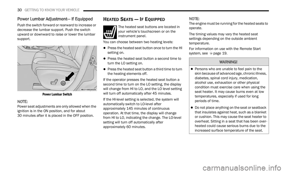
Power Lumbar Adjustment— If Equipped
Push the switch forward or rearward to increase or
decrease the lumbar support. Push the switch
upward or downward to raise or lower the lumbar
support.
Power Lumbar Switch
NOTE:
Power seat adjustments are only allowed when the
ignit i
on is in the ON position, and for about
30 minutes after it is placed in the OFF position.
HEATED SEATS — IF EQUIPPED
The heated seat buttons are located in
your vehicle’s touchscreen or on the
instr u
ment panel.
You can choose between two heating levels:
Press the heated seat button once to turn the HI
setting on.
Press the heated seat button a second time to
turn the LO setting on.
Press the heated seat button a third time to turn
the heating elements off.
If the operator presses the heated seat button a
second
time to turn on the LO setting, the display
will change from HI to LO, and the LO level setting
will turn off automatically after 45 minutes.
If the HI-level setting is selected, the system will
a utomat
ically switch to LO-level after
approximately 145 minutes of continuous
operati
on. At that time, the display will change
from HI to LO, indicating the change. The LO-level
setting will turn off automatically after
approximately 60 minutes.
NOTE:
The engine must be running for the heated seats to
operat e
.
The timing values may vary the heated seat
settin
gs depending on the outside ambient
temperature.
For information on use with the Remote Start
syste m
, see Ú page 19.
WARNING!
Persons who are unable to feel pain to the
skin because of advanced age, chronic illness,
diabetes, spinal cord injury, medication,
alcohol use, exhaustion or other physical
condition must exercise care when using the
seat heater. It may cause burns even at low
temperatures, especially if used for long
periods of time.
Do not place anything on the seat or seatback
that insulates against heat, such as a blanket
or cushion. This may cause the seat heater to
overheat. Sitting in a seat that has been over
-
heated could cause serious burns due to the
i ncrea
sed surface temperature of the seat.
Page 35 of 364
GETTING TO KNOW YOUR VEHICLE 33
UCONNECT VOICE RECOGNITION
INTRODUCING VOICE RECOGNITION
Start using Uconnect Voice Recognition with these
helpful quick tips. It provides the key Voice
Commands and tips you need to know to control
your vehicle’s Voice Recognition (VR) system.
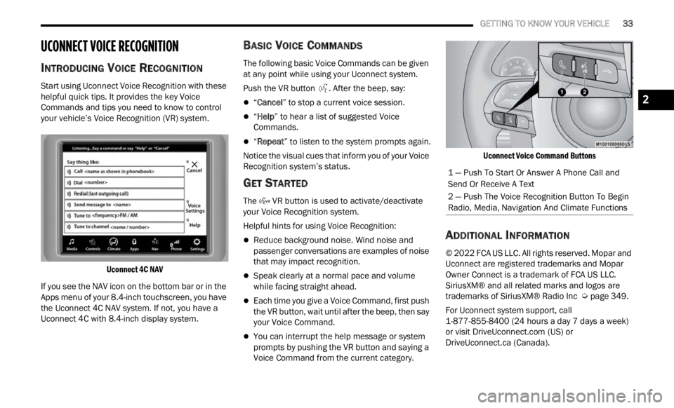
Uconnect 4C NAV
If you see the NAV icon on the bottom bar or in the
Apps m
enu of your 8.4-inch touchscreen, you have
the Uconnect 4C NAV system. If not, you have a
Uconnect 4C with 8.4-inch display system.
BASIC VOICE COMMANDS
The following basic Voice Commands can be given
at any point while using your Uconnect system.
Push the VR button . After the beep, say:
“Cancel ” to stop a current voice session.
“Help ” to hear a list of suggested Voice
Commands.
“ Repeat ” to listen to the system prompts again.
Notice the visual cues that inform you of your Voice
Recogn i
tion system’s status.
GET STARTED
The VR button is used to activate/deactivate
your Voice Recognition system.
Helpful hints for using Voice Recognition:
Reduce background noise. Wind noise and
passenger conversations are examples of noise
that may impact recognition.
Speak clearly at a normal pace and volume
while facing straight ahead.
Each time you give a Voice Command, first push
the VR button, wait until after the beep, then say
your Voice Command.
You can interrupt the help message or system
prompts by pushing the VR button and saying a
Voice Command from the current category.
Uconnect Voice Command Buttons
ADDITIONAL INFORMATION
© 2022 FCA US LLC. All rights reserved. Mopar and
Uconnect are registered trademarks and Mopar
Owner Connect is a trademark of FCA US LLC.
SiriusXM® and all related marks and logos are
trademarks of SiriusXM® Radio Inc
Ú page 349.
For Uconnect system support, call
1-877 -
855-8400 (24 hours a day 7 days a week)
or visit DriveUconnect.com (US) or
DriveUconnect.ca (Canada).
1 — Push To Start Or Answer A Phone Call and
Send Or Receive A Text
2 — Push The Voice Recognition Button To Begin
Radio, Media, Navigation And Climate Functions
2
Page 39 of 364
GETTING TO KNOW YOUR VEHICLE 37
Turning on the headlights will illuminate the
instrument cluster and the controls located on the
instrument panel.
NOTE:
On vehicles sold in Canada, both the rear position
light s
and Daytime Running Lights (DRLs) will turn
on when the headlight switch is rotated to the O
(off) position.
DAYTIME RUNNING LIGHTS (DRLS) —
I
F EQUIPPED
The Daytime Running Lights (DRLs), if enabled
through Uconnect Settings, will turn on when the
instrument cluster is on and remain on unless the
headlights are turned on or the instrument cluster
is switched off.
NOTE:
For vehicles sold in Canada, the Daytime
Running Lights will automatically deactivate
when the front fog lights are turned on.
On some vehicles, the Daytime Running Lights
may deactivate, or reduce intensity, on one side
of the vehicle (when a turn signal is activated on
that side), or on both sides of the vehicle (when
the hazard warning lights are activated).
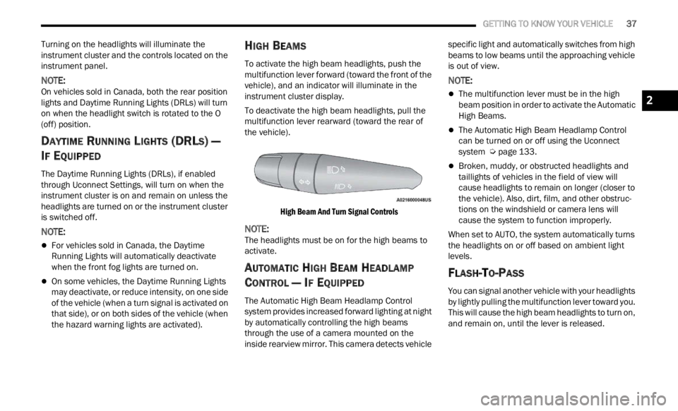
HIGH BEAMS
To activate the high beam headlights, push the
multifunction lever forward (toward the front of the
vehicle), and an indicator will illuminate in the
instrument cluster display.
To deactivate the high beam headlights, pull the
multif
unction lever rearward (toward the rear of
the vehicle).
High Beam And Turn Signal Controls
NOTE:
The headlights must be on for the high beams to
activ a
te.
AUTOMATIC HIGH BEAM HEADLAMP
C
ONTROL — IF EQUIPPED
The Automatic High Beam Headlamp Control
system provides increased forward lighting at night
by automatically controlling the high beams
through the use of a camera mounted on the
inside rearview mirror. This camera detects vehicle specific light and automatically switches from high
beams to low beams until the approaching vehicle
is out of view.
NOTE:
The multifunction lever must be in the high
beam position in order to activate the Automatic
High Beams.
The Automatic High Beam Headlamp Control
can be turned on or off using the Uconnect
system
Ú page 133.
Broken, muddy, or obstructed headlights and
taillights of vehicles in the field of view will
cause headlights to remain on longer (closer to
the vehicle). Also, dirt, film, and other obstruc
-
tions on the windshield or camera lens will
c ause
the system to function improperly.
When set to AUTO, the system automatically turns
the he
adlights on or off based on ambient light
levels.
FLASH-TO-PASS
You can signal another vehicle with your headlights
by lightly pulling the multifunction lever toward you.
This will cause the high beam headlights to turn on,
and remain on, until the lever is released.
2
Page 40 of 364
38 GETTING TO KNOW YOUR VEHICLE
AUTOMATIC HEADLIGHTS — IF EQUIPPED
This system automatically turns the headlights on
or off according to ambient light levels. To turn the
system on, rotate the headlight switch clockwise to
the last detent (AUTO position) for automatic
headlight operation. To turn the automatic system
off, move the headlight switch out of the AUTO
position.
NOTE:
The ignition must be in the ON/RUN or START
positi on
before the headlights will come on in the
automatic mode.
Dusk Sensor
There is an infrared LED sensor that works with the
rain sensor, located on the windshield. It detects
changes in light intensity outside the vehicle,
based on the sensitivity of light set by using the
menu on the display or on the Uconnect system.
The higher the sensitivity, the lesser the amount of
exter n
al light required for controlling the lighting.
To turn the dusk sensor on, rotate the headlight
switch
to the AUTO position. To turn it off, rotate the
headlight switch to a position other than AUTO.
NOTE:
The dusk sensor can only be activated with the
ignit i
on in the ON/RUN position.
PARKING LIGHTS
Rotate the headlight switch to the first detent to
turn on the parking lights. The parking light
indicator in the instrument cluster display will
illuminate.
HEADLIGHT TIME DELAY
This feature provides the safety of headlight
illumination for up to 90 seconds when leaving
your vehicle in an unlit area.
The time delay of the headlights is programmable
betwe e
n 0, 30, 60 and 90 seconds within
Uconnect Settings Ú page 133.
Headlight Delay Activation
To activate the delay feature, place the ignition in
t he OF
F position while the headlights are still on.
The delay interval begins when the headlight
switch is turned off from the low beam position.
If the headlight switch is in AUTO and the
headli
ghts were on before the ignition was turned
off, the delay interval begins automatically.
Headlight Delay Deactivation
The feature is disabled by turning on the
h eadli
ghts, the parking lights or by placing the
ignition in the RUN position.
If you shut off the lights before the ignition is
turne d
on, they will turn off in the normal manner.
NOTE:
The lights must be turned off within two minutes of
placi n
g the ignition in the OFF position to activate
this feature.
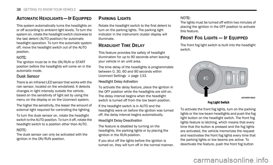
FRONT FOG LIGHTS — IF EQUIPPED
The front fog light switch is built into the headlight
switch.
Fog Light Switch
To activate the front fog lights, turn on the parking
light s
or the low beam headlights and push the fog
light button on the headlight switch. The front fog
lights feature is latching, which means that every
time that the button is pressed and the fog lights
are activated, the vehicle memorizes the request
and reactivates the front fog lights every time that
the parking lights or low beams are active. To
deactivate the feature, push the front fog button