display JEEP RENEGADE 2023 User Guide
[x] Cancel search | Manufacturer: JEEP, Model Year: 2023, Model line: RENEGADE, Model: JEEP RENEGADE 2023Pages: 364, PDF Size: 18.65 MB
Page 41 of 364
GETTING TO KNOW YOUR VEHICLE 39
again. The front fog lights are deactivated each
time the parking or low beam lights are
deactivated or the ignition is placed in the OFF
position.
An indicator light in the instrument cluster
illumi
nates when the fog lights are turned on.
NOTE:
The fog lights will operate with the low beam head -
lights or parking lights on. Selecting the high beam
h eadl i
ghts will turn off the fog lights.
Cornering Lights
The cornering lights are a feature to improve
visib i
lity at night while turning the vehicle. When
activated, a light incorporated in the front fog light
will illuminate on the side of the vehicle the
steering wheel is rotated or the turn signal
indicator is on. It can be activated through the
Uconnect system Ú page 133.
TURN SIGNALS
Move the multifunction lever up or down to
activate the turn signals. The arrows on each side
of the instrument cluster display flash to show
proper operation.
LANE CHANGE ASSIST
Lightly push the multifunction lever up or down,
without moving beyond the detent, and the turn
signal will flash five times then automatically turn
off.
COURTESY LIGHTS
The courtesy lights feature allows you to activate
the low beam, parking lights, and sidemarker lights
for 25 seconds when the vehicle is unlocked
(through the key fob or the Passive Entry door
handles [if equipped]). The courtesy lights feature
can be activated or deactivated through the
Uconnect Settings. When a door is open with the
feature active, the activation of the lights is
extended for five seconds. The feature is disabled
when the vehicle is locked or when the ignition is
placed in the ON/RUN position.
INTERIOR LIGHTS
FRONT MAP/READING LIGHTS
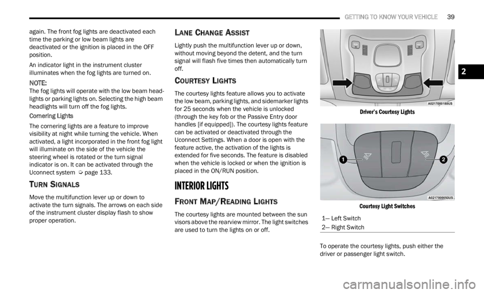
The courtesy lights are mounted between the sun
visors above the rearview mirror. The light switches
are used to turn the lights on or off.
Driver’s Courtesy Lights
Courtesy Light Switches
To operate the courtesy lights, push either the
d rive
r
or passenger light switch.
1— Left Switch
2— Right Switch
2
Page 46 of 364
44 GETTING TO KNOW YOUR VEHICLE
Activation By Rear Defrost — The Windshield
Wiper De-Icer will be activated automatically
when the rear defrost is turned on and the
ambient temperature is below 40°F (4.4°C).
Activation By Remote Start Operation — When
Remote Start is active and the outside ambient
temperature is less than 40°F (4.4°C), the
Windshield Wiper De-Icer will activate. Exiting
Remote Start will resume its previous operation.
If the Windshield Wiper De-Icer was active, the
timer and operation will continue Ú page 133.
Auto-On Rear Window Defroster/Windshield Wiper
De-Ic e
r — If Equipped
When placing the vehicle’s ignition in the ON/RUN
position
, the Rear Window Defroster and
Windshield Wiper De-Icer will automatically turn on
when the outside ambient temperature is less than
40°F (4.4°C).
The Rear Window Defroster and Windshield Wiper
De-Ic e
r automatically turn off after approximately
20 minutes. To manually shut the defroster/
windsh
ield off, push the Rear Defrost button.
Auto On can be enabled or disabled through the
Uconnec
t Settings Ú page 133.
CLIMATE CONTROLS
The Climate Control system allows you to regulate
the temperature, air flow, and direction of air
circulating throughout the vehicle. The controls are located on the touchscreen (if equipped) and on
the instrument panel below the radio.
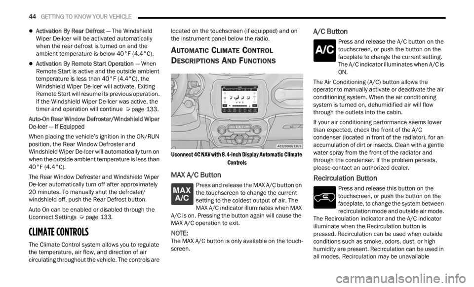
AUTOMATIC CLIMATE CONTROL
D
ESCRIPTIONS AND FUNCTIONS
Uconnect 4C NAV with 8.4-inch Display Automatic Climate
Controls
MAX A/C Button
Press and release the MAX A/C button on
the touchscreen to change the current
se t
ti
n
g to the coldest output of air. The
MAX A/C indicator illuminates when MAX
A/C is on. Pressing the button again will cause the
MAX A/C operation to exit.
NOTE:
The MAX A/C button is only available on the touch -
screen.
A/C Button
Press and release the A/C button on the
touchscreen, or push the button on the
facep l
ate to change the current setting.
The A/C indicator illuminates when A/C is
ON.
The Air Conditioning (A/C) button allows the
operator
to manually activate or deactivate the air
conditioning system. When the air conditioning
system is turned on, dehumidified air will flow
through the outlets into the cabin.
If your air conditioning performance seems lower
than e
xpected, check the front of the A/C
condenser (located in front of the radiator), for an
accumulation of dirt or insects. Clean with a gentle
water spray from the front of the radiator and
through the condenser. If the problem persists,
please contact an authorized dealer.
Recirculation Button
Press and release this button on the
touchscreen, or push the button on the
f a c
e p
l
ate, to change the system between
recirculation mode and outside air mode.
The Recirculation indicator and the A/C indicator
illuminate when the Recirculation button is
pressed. Recirculation can be used when outside
conditions such as smoke, odors, dust, or high
humidity are present. Recirculation can be used in
all modes. Recirculation may be unavailable
Page 49 of 364

GETTING TO KNOW YOUR VEHICLE 47
AUTOMATIC TEMPERATURE CONTROL
(ATC)
Automatic Operation
1. Push the AUTO button on the faceplate, or the
AUTO button on the touchscreen on the
Automatic Temperature Control (ATC) Panel.
2. Adjust the temperature you would like the syste
m to maintain, by adjusting the driver,
and passenger temperatures. Once the
desired temperature is displayed, the system
will achieve and automatically maintain that
comfort level.
3. When the system is set up for your comfort level
, it is not necessary to change the
settings. You will experience the greatest
efficiency by simply allowing the system to
function automatically.
NOTE:
It is not necessary to move the temperature
settings. The system automatically adjusts the
temperature, mode, and fan speed to provide
comfort as quickly as possible.
The temperature can be displayed in U.S. or
Metric units by selecting the U.S./Metric
customer programmable feature within
Uconnect Settings. To provide you with maximum comfort in the
automa
t
ic mode, during cold start-ups, the blower
fan will remain on low until the engine warms up.
The fan will engage immediately if the Defrost
mode is selected, or by changing the front blower
knob setting.
Manual Operation Override
This system offers a full complement of manual
override features. The AUTO symbol in the front
ATC display will be turned off when the system is
being used in the manual mode.
CLIMATE VOICE COMMANDS
Adjust vehicle temperatures hands-free and keep
everyone comfortable while you keep moving
ahead.
Push the VR button on the steering wheel. After the
beep,
say one of the following commands:
“Set the driver temperature to 70 degrees ”
“Set the passenger temperature to 70 degrees ”
Did You Know:
V oi
ce
Command for Climate may
only be used to adjust the interior temperature of
your vehicle. Voice Command will not adjust the
heated seats or steering wheel if equipped.
OPERATING TIPS
Refer to the chart at the end of this section for
suggested control settings for various weather
conditions.
Summer Operation
The engine cooling system must be protected with
a high-quality antifreeze coolant to provide proper
corrosion protection and to protect against engine
overheating. OAT coolant (conforming to
MS.90032) is recommended.
Winter Operation
To ensure the best possible heater and defroster
performance, make sure the engine cooling
system is functioning properly and the proper
amount, type, and concentration of coolant is
used. Use of the Air Recirculation mode during
Winter months is not recommended, because it
may cause window fogging.
Vacation/Storage
For information on maintaining the Climate Control
system when the vehicle is being stored for an
extended period of time, see Ú page 338.
Window Fogging
Vehicle windows tend to fog on the inside in mild,
rainy, and/or humid weather. To clear the
windows, select Defrost or Mix mode and increase
the front blower speed. Do not use the
Recirculation mode without A/C for long periods,
as fogging may occur.
Outside Air Intake
Make sure the air intake, located directly in front of
the windshield, is free of obstructions, such as
2
Page 66 of 364
64 GETTING TO KNOW YOUR INSTRUMENT PANEL
INSTRUMENT CLUSTER DESCRIPTIONS
1. Tachometer
Indicates the engine speed in revolutions
per minute (RPM x 1000).
2. Instrument Cluster Display
The instrument cluster display features a
driver interactive display Ú page 64.
3. Speedometer
Indicates vehicle speed.
4. T emperature Gauge
The temperature gauge shows engine
coolant temperature. Any reading within the
normal range indicates that the engine
cooling system is operating satisfactorily.
The gauge will likely indicate a higher
temperature when driving in hot weather or
up mountain grades. It should not be
allowed to exceed the upper limits of the
normal operating range. 5. Fuel Gauge
The fuel gauge shows the level of fuel in the
fuel tank when the ignition is in the ON/RUN
position.
The fuel pump symbol points to the
side of the vehicle where the fuel
d oor
is
located.
INSTRUMENT CLUSTER DISPLAY
Your vehicle is equipped with an instrument cluster
display, which offers useful information to the
driver. With the ignition in the OFF position,
opening/closing of a door will activate the display
for viewing, and display the total miles, or
kilometers, in the odometer. Your instrument
cluster display is designed to display important
information about your vehicle’s systems and
features. Using a driver interactive display located on the instrument panel, your instrument cluster
display can show you how systems are working and
give you warnings when they aren’t. The steering
wheel mounted controls allow you to scroll through
and enter the main menus and submenus. You can
access the specific information you want and
make selections and adjustments.
INSTRUMENT CLUSTER DISPLAY
L
OCATION AND CONTROLS
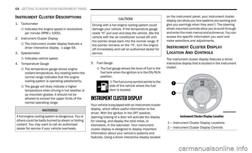
The instrument cluster display features a driver
interactive display that is located in the instrument
cluster.
Instrument Cluster Display Location
WARNING!
A hot engine cooling system is dangerous. You or
others could be badly burned by steam or boiling
coolant. You may want to call an authorized
dealer for service if your vehicle overheats.
CAUTION!
Driving with a hot engine cooling system could
damage your vehicle. If the temperature gauge
reads “H” pull over and stop the vehicle. Idle the
vehicle with the air conditioner turned off until
the pointer drops back into the normal range. If
the pointer remains on the “H”, turn the engine
off immediately and call an authorized dealer for
service.
1 — Instrument Cluster Display Locations
2 — Instrument Cluster Display Controls
Page 67 of 364
GETTING TO KNOW YOUR INSTRUMENT PANEL 65
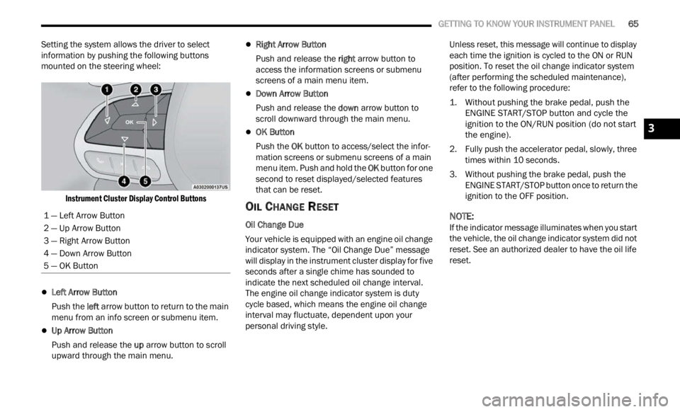
Setting the system allows the driver to select
information by pushing the following buttons
mounted on the steering wheel:
Instrument Cluster Display Control Buttons
Left Arrow Button
Push the l
eft a
rr
ow
button to return to the main
menu from an info screen or submenu item.
Up Arrow Button
Push and release the u
p a
rr
ow
button to scroll
upward through the main menu.
Right Arrow Button
Push and release the right
arrow button to
access the information screens or submenu
screens of a main menu item.
Down Arrow Button
Push and release the d
ow n
a r
r
ow button to
scroll downward through the main menu.
OK Button
Push the O
K b
ut
t
on to access/select the infor -
mation screens or submenu screens of a main
menu i
tem. Push and hold the OK button for one
second to reset displayed/selected features
that can be reset.
OIL CHANGE RESET
Oil Change Due
Your vehicle is equipped with an engine oil change
indic a
tor system. The “Oil Change Due” message
will display in the instrument cluster display for five
seconds after a single chime has sounded to
indicate the next scheduled oil change interval.
The engine oil change indicator system is duty
cycle based, which means the engine oil change
interval may fluctuate, dependent upon your
personal driving style. Unless reset, this message will continue to display
each
t
ime the ignition is cycled to the ON or RUN
position. To reset the oil change indicator system
(after performing the scheduled maintenance),
refer to the following procedure:
1. Without pushing the brake pedal, push the ENGI N
E START/STOP button and cycle the
ignition to the ON/RUN position (do not start
the engine).
2. Fully push the accelerator pedal, slowly, three times
within 10 seconds.
3. Without pushing the brake pedal, push the ENGIN
E START/STOP button once to return the
ignition to the OFF position.
NOTE:
If the indicator message illuminates when you start
the v e
hicle, the oil change indicator system did not
reset. See an authorized dealer to have the oil life
reset.
1 — Left Arrow Button
2 — Up Arrow Button
3 — Right Arrow Button
4 — Down Arrow Button
5 — OK Button
3
Page 68 of 364
66 GETTING TO KNOW YOUR INSTRUMENT PANEL
INSTRUMENT CLUSTER DISPLAY MENU
I
TEMS
NOTE:
The instrument cluster display menu items display
in th e
center of the instrument cluster. Menu items
may vary depending on your vehicle features.
Speedometer
Push and release the up or down arrow
button until the speedometer is displayed in the
i n s
tr
u
ment cluster display. Push and release the
OK button to toggle units (mph or km/h) of the
speedometer.
Vehicle Info
Push and release the up or down arrow
button until “Vehicle Info” is highlighted in the
instr u
ment cluster display. Push and release the
right arrow button and Coolant Temp will be
displayed. Push the right
or left arrow button
to sc
roll through the following information displays:
Tire Pressure — View the information relating to
the Tire Pressure Monitoring System (If
Equipped).
Coolant Temperature — View the engine coolant
temperature.
Trans Temperature — View the trans oil
temperature.
Oil Temperature — View the oil temperature.
Battery Voltage — View the voltage value (state
of charge) of the battery.
Service — View the service status message(s) (If
Equipped).
Driver Assist — If Equipped
Push and release the up or down arrow
button until the Driver Assist menu title displayed
is hi g
hlighted in the instrument cluster display.
LaneSense — If Equipped
The instrument cluster display displays the current
LaneSe n
se status and information. The
information displayed depends on LaneSense
system status and the conditions that need to be
met Ú page 133.
Fuel Economy
This menu item allows you to view the fuel
economy of the vehicle. The following will display:
Range (Miles or km)
Current Consumption (mpg or L/100 km or
km/L)
Average Consumption (mpg or L/100 km or
km/L)
Reset procedure shown at the bottom of the
d ispla
y.
Trip Info
Push and release the up or down arrow
button until the Trip menu title is displayed in the
instr u
ment cluster display. Toggle the left
or
right arrow button to select Trip A or Trip B. The
Trip information will display the following:
Distance – Shows the total distance (mi or km)
traveled for Trip A or Trip B since the last reset.
Average Fuel Economy – Shows the average
fuel economy (MPG or L/100 km or km/L) of
Trip A
or Trip B since the last reset.
Elapsed Time – Shows the total elapsed time of
travel since Trip A or Trip B has been reset.
Hold the OK butt
on to reset feature information.
Stop/Start – If Equipped
Push and release the up or down arrow
button until the Stop/Start menu title is displayed
i n
t h
e
instrument cluster display.
This menu shows messages related to Stop/Start.
Only on
e message can be viewed at a time until the
condition is cleared. When the Stop/Start is
engaged (and the engine is off), the associated
hardware telltale is turned on. Whenever a user
pushes the Stop/Start button on the central stack,
a pop-up message of the Stop/Start status will
appear on the instrument cluster display.
Page 69 of 364

GETTING TO KNOW YOUR INSTRUMENT PANEL 67
Audio
Push and release the up or down arrow
button until the Audio menu title is displayed in the
instr u
ment cluster display.
Stored Messages
Push and release the up or down arrow
button until the Messages Menu Icon is highlighted
in th e
instrument cluster display. This feature
shows the number of stored warning messages.
Pushing the left
or right arrow button will
all ow
you to scroll through the stored messages.
Screen Setup
This menu item allows you to change the position
of the information on the display.
Display Gears (Vehicles With Reconfigurable
Multi-
Functional Display And Automatic
Transmission)
By selecting this item, you can select the display
mode, t
he particulars relating to the automatic
transmission, and choose between the following
options:
“Single digit”
The right side of the display will show the letter
concer n
ing the automatic transmission gear
selector (P,R,N or D) position. After approxi -
mately two seconds, the letter will be displayed
in a c
entral position.
“Full PRND”
The letters PRND will display on the right side,
the p o
sition assumed by the gear selector will
be highlighted in the display. During the opera -
tion in sequential mode (“AutoStick”), in place
of the
letter D, the gear will be will be displayed.
In The Upper Left/Top Right
The information relating to the following can be
displ a
yed:
External temperature
Ignition Button — If Equipped
Compass — If Equipped
Date (Month/Day)
Time (Hours/Minutes)
In the central area of the display, you can view all
of t
h e
information listed above as well as the
following:
Compass — If Equipped
Speed Display — If Equipped
Date (Day/Month/Year)
Time
Compass — If Equipped
Ignition Button — If Equipped
External Temp — If equipped
Menu Item
Distance Traveled A (Trip A)
Distance Traveled B (Trip B)
Restore Default Settings
Selecting this item, and you can reset and restore
t he de
fault settings.
Settings
This menu item allows you to change the settings
for the following:
Display
Units
Clock and Date
Security
Safety and Assistance
Lights
Doors and Locks
NOTE:
Some items may be displayed and managed
throug h
the Uconnect system.
Vehicles Equipped With Multi-functional Display
Reconfi
gurable:
The following menu/submenu items are available
in the
cluster display.
3
Page 70 of 364

68 GETTING TO KNOW YOUR INSTRUMENT PANEL
“Vehicle Shut Off (If Equipped)”
By selecting the item “Vehicle Shut Off”, you can
turn of
f the engine from the instrument cluster.
This feature is available in the event of an ignition
switch failure, and will display instructions for
turning off the engine via the instrument cluster
display controls.
“Display”
By selecting the “Display,” you can access the
follow i
ng setting:
Language : allows you to select the language in
which to display the information/warnings.
“Units Of Measure”
By selecting the item “Units of Measure,” you can
selec t
the unit of measure to use for displaying
various magnitudes.
Possible options are:
US
Metric
Custom
“Clock & Date”
By selecting the item, “Clock & Date” you can
a djust
the clock.
Possible options are:
Set Time: adjust hours/minutes
Set Format: adjust the time format “12h”
(12 hours) or “24h” (24 hours)
Set Date: adjust day/month/year
“Security”
By selecting the item “Security,” you can make the
f ollowi
ng adjustments:
Speed Warning:
Set the vehicle speed limit, which the driver is
notifi e
d through a visual and acoustic signaling
(display of a message and a symbol on the
display).
When the speed warning is set, the icon should
remain
visualized for the same duration time of
the pop-up. If the driver exceeded the set speed,
the icon should remain for however long the
vehicle is over the set speed.
Driver may also turn the Speed Warning “OFF”
should
you choose not to use this feature.
Seat Belt Reminder:
This function is only viewable when the Seat Belt
Remin d
er (SBR) system is active.
Hill Start Assist:
Activation/Deactivation of the Hill Start Assist
syste m
.
Passenger Air Bag — If Equipped
Front passenger air bag may be enabled or
disab l
ed. “Lights”
By selecting the item “Lights,” you can make the
followi
n
g adjustments:
Headlight Off Delay: set the delay for headlight
shutoff after engine shutoff
Headlight Sensitivity: adjust the sensitivity of
headlight brightness
Daytime Running Lights: activate/deactivate
the daytime running lights
Cornering lights: activate/deactivate the
cornering lights (If Equipped)
Interior Ambient lights: adjust the level of inte-
rior ambient lights
Greeting Lights: activate / deactivate greeting
lights
“Doors & Locks”
By selecting the item “Doors & Locks,” you can
make t
he following adjustments:
Auto Door Lock: activate/deactivate the auto -
matic locking of the doors with the vehicle
m ov i
n g
Auto Unlock On Exit: automatic unlocking of the
doors when exiting the vehicle
Flash Light with Lock: activate the direction indi
-
cators when closing the doors
Page 71 of 364

GETTING TO KNOW YOUR INSTRUMENT PANEL 69
Sound Horn With Lock: activate/deactivate the
horn when pushing the LOCK button on the key
fob. The options are “Off,” “First Press,” and
“Second Press”
Horn With Remote Start: activate/deactivate
the horn at the Remote Starting of the engine
with the key fob
Remote Door Unlock: allows you to open the
driver door only on the first push of the UNLOCK
button on the key fob
“Compass”
By selecting the item “Compass” you can make the
f ollowi
ng adjustments:
Compass Calibration
Compass Variance
TRIP COMPUTER
The Trip computer is used to display information on
car operation when the key is turned to the RUN
position.
This function allows you to define two separate
trips
called “Trip A” and “Trip B” where the car's
“complete trips” are monitored in an independent
manner.
Both trips can be reset (reset - start of a new trip).
To perf
orm a reset, push and hold the OK button on
the steering wheel controls. “Trip A” and “Trip B” are used to display the figures
relat
i
ng to:
Distance Traveled
Average Consumption
Travel Time (driving time)
Quantities Displayed
Distance Traveled
Indicates the distance traveled by the start of
the new trip.
Average Consumption
Represents the average fuel consumption since
the start of the new trip.
Travel Time
Elapsed time since the start of the new trip.
OK Button
Short Push Of The Button: display of various
p arame
ters.
Long Push Of The Button: reset quantities and
begin
a new trip.
New trip
Starts after reset:
“Manual” by pushing the OK button.
“Automatic” when the “distance” reaches the
value of 62140 (99999.9 km) or when the “time
travel” reaches the value of 999.59
(999 hours and 59 minutes).
After each disconnection and reconnection of
the battery.
WARNING/INDICATOR LIGHTS AND
MESSAGES
The warning/indicator light switches on in the
instrument panel together with a dedicated
message and/or acoustic signal when applicable.
These indications are indicative and precautionary
and as such must not be considered as exhaustive
and/or alternative to the information contained in
the Owner Manual, which you are advised to read
carefully in all cases. Always refer to the
information in this chapter in the event of a failure
indication.
All active telltales will display first, if applicable.
The sy
stem check menu may appear different
based upon equipment options and current vehicle
status. Some telltales are optional and may not
appear.
The following warning lamps and indicators will
alert
you to a vehicle condition that may become
serious. Some lamps will illuminate when you start
your vehicle to make sure they work. If any lamps
remain on after starting your vehicle, refer to the
respective system warning lamp for further
information.
3
Page 76 of 364
74 GETTING TO KNOW YOUR INSTRUMENT PANEL
Service Forward Collision Warning (FCW)
Light — If Equipped
This warning light will illuminate to
indicate a fault in the Forward Collision
W
ar
n i
n
g System. Contact an authorized
dealer for service Ú page 232.
Service Stop/Start System Warning Light —
If Equipped
This warning light will illuminate when the
Stop/Start system is not functioning
p
rop
er
l
y and service is required. Contact
an authorized dealer for service.
Tire Pressure Monitoring System (TPMS)
Warning Light
The warning light switches on and a
message is displayed to indicate that the
tire p
ressure is lower than the
recommended value and/or that slow
pressure loss is occurring. In these cases, optimal
tire duration and fuel consumption may not be
guaranteed.
Should one or more tires be in the condition
mention
ed above, the display will show the
indications corresponding to each tire. Each tire, including the spare (if provided), should
be ch
e
cked monthly when cold and inflated to the
inflation pressure recommended by the vehicle
manufacturer on the vehicle placard or tire
inflation pressure label. If your vehicle has tires of
a different size than the size indicated on the
vehicle placard or tire inflation pressure label, you
should determine the proper tire inflation pressure
for those tires.
As an added safety feature, your vehicle has been
equip p
ed with a TPMS that illuminates a low tire
pressure telltale when one or more of your tires is
significantly underinflated. Accordingly, when the
low tire pressure telltale illuminates, you should
stop and check your tires as soon as possible, and
inflate them to the proper pressure. Driving on a
significantly underinflated tire causes the tire to
overheat and can lead to tire failure. Underinflation
also reduces fuel efficiency and tire tread life, and
may affect the vehicle’s handling and stopping
ability. Please note that the TPMS is not a substitute for
proper
tire maintenance, and it is the driver’s
responsibility to maintain correct tire pressure,
even if underinflation has not reached the level to
trigger illumination of the TPMS low tire pressure
telltale.
Your vehicle has also been equipped with a TPMS
malfu n
ction indicator to indicate when the system
is not operating properly. The TPMS malfunction
indicator is combined with the low tire pressure
telltale. When the system detects a malfunction,
the telltale will flash for approximately one minute
and then remain continuously illuminated. This
sequence will continue upon subsequent vehicle
start-ups as long as the malfunction exists. When
the malfunction indicator is illuminated, the
system may not be able to detect or signal low tire
pressure as intended. TPMS malfunctions may
occur for a variety of reasons, including the
installation of replacement or alternate tires or
wheels on the vehicle that prevent the TPMS from
functioning properly. Always check the TPMS
malfunction telltale after replacing one or more
tires or wheels on your vehicle to ensure that the
replacement or alternate tires and wheels allow
the TPMS to continue to function properly.
CAUTION!
Do not continue driving with one or more flat
tires as handling may be compromised. Stop the
vehicle, avoiding sharp braking and steering. If a
tire puncture occurs, repair immediately using
the dedicated tire repair kit and contact an
authorized dealer as soon as possible.