electrical JEEP WAGONEER 2023 User Guide
[x] Cancel search | Manufacturer: JEEP, Model Year: 2023, Model line: WAGONEER, Model: JEEP WAGONEER 2023Pages: 396, PDF Size: 15.17 MB
Page 161 of 396
STARTING AND OPERATING159
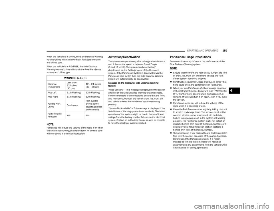
When the vehicle is in DRIVE, the Side Distance Warning
volume/chime will match the Front ParkSense volume
and chime type.
When the vehicle is in REVERSE, the Side Distance
Warning volume/chime will match the Rear ParkSense
volume and chime type.
NOTE:Parksense will reduce the volume of the radio if on when
the system is sounding an audible tone. An audible tone
will only sound if a collision is possible.
Activation/Deactivation
The system can operate only after driving a short distance
and if the vehicle speed is between 0 and 7 mph
(0 and 11 km/h). The system can be activated/
deactivated via the Settings menu of the Uconnect
system. If the ParkSense System is deactivated via the
ParkSense hard switch then the Side Distance Warning
system will automatically be deactivated.
Message on the display for Side Distance Warning
feature:
“Wipe Sensors” — This message is displayed in the case of
a failure of the Side Distance Warning system sensors.
Free the bumpers of any obstacles, ensure that the front
and rear fascia/bumper are free of snow, ice, mud, dirt
and debris to keep the ParkSense system operating
properly.
“System Not Available” — This message is displayed if the
Side Distance Warning system is not available. The failed
operation of the system might be due to the insufficient
voltage from the battery or other failures on the electrical
system. Contact an authorized dealer as soon as possible
to have the electrical system checked.
ParkSense Usage Precautions
Some conditions may influence the performance of the
Side Distance Warning system:
NOTE:
Ensure that the front and rear fascia/bumper are free
of snow, ice, mud, dirt and debris to keep the Park -
Sense system operating properly.
Construction equipment, large trucks, and other vibra -
tions could affect the performance of ParkSense.
When you turn ParkSense off, the message to appear
in the instrument cluster display will read “PARKSENSE
OFF.” Furthermore, once you turn ParkSense off, it
remains off until you turn it on again, even if you cycle
the ignition.
ParkSense, when on, will reduce the volume of the
radio when it is sounding a tone.
Clean the ParkSense sensors regularly, taking care not
to scratch or damage them. The sensors must not be
covered with ice, snow, slush, mud, dirt or debris.
Failure to do so can result in the system not working
properly. The ParkSense system might not detect an
obstacle behind or in front of the fascia/bumper, or it
could provide a false indication that an obstacle is
behind or in front of the fascia/bumper.
The presence of a tow hook without a trailer may inter -
fere with the correct operation of the parking sensors.
Before using the ParkSense system, it is recom -
mended to remove the removable tow hook ball
assembly and any attachments from the vehicle when
it is not used for towing operations.
WARNING ALERTS
Distance
(inches/cm) Less than
12 inches
(30 cm)12 – 24 inches
(30 – 60 cm)
Arcs-Left 11th Flashing 12th Flashing
Arcs-Right 11th Flashing 12th Flashing
Audible Alert
Chime ContinuousFast audible
chime as the
objects get close
to the vehicle
Radio Volume
Reduced Yes
Yes
4
23_WS_OM_EN_USC_t.book Page 159
Page 189 of 396
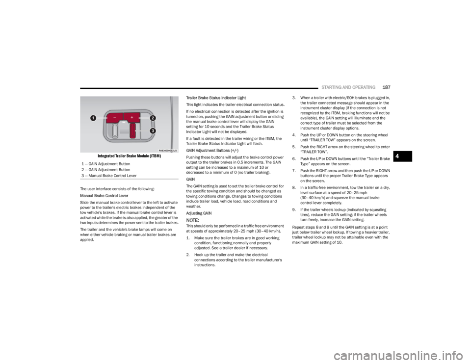
STARTING AND OPERATING187
Integrated Trailer Brake Module (ITBM)
The user interface consists of the following:
Manual Brake Control Lever
Slide the manual brake control lever to the left to activate
power to the trailer's electric brakes independent of the
tow vehicle's brakes. If the manual brake control lever is
activated while the brake is also applied, the greater of the
two inputs determines the power sent to the trailer brakes.
The trailer and the vehicle's brake lamps will come on
when either vehicle braking or manual trailer brakes are
applied. Trailer Brake Status Indicator Light
This light indicates the trailer electrical connection status.
If no electrical connection is detected after the ignition is
turned on, pushing the GAIN adjustment button or sliding
the manual brake control lever will display the GAIN
setting for 10 seconds and the Trailer Brake Status
Indicator Light will not be displayed.
If a fault is detected in the trailer wiring or the ITBM, the
Trailer Brake Status Indicator Light will flash.
GAIN Adjustment Buttons (+/-)
Pushing these buttons will adjust the brake control power
output to the trailer brakes in 0.5 increments. The GAIN
setting can be increased to a maximum of 10 or
decreased to a minimum of 0 (no trailer braking).
GAIN
The GAIN setting is used to set the trailer brake control for
the specific towing condition and should be changed as
towing conditions change. Changes to towing conditions
include trailer load, vehicle load, road conditions and
weather.
Adjusting GAIN
NOTE:This should only be performed in a traffic free environment
at speeds of approximately 20–25 mph (30–40 km/h).
1. Make sure the trailer brakes are in good working condition, functioning normally and properly
adjusted. See a trailer dealer if necessary.
2. Hook up the trailer and make the electrical connections according to the trailer manufacturer's
instructions. 3. When a trailer with electric/EOH brakes is plugged in,
the trailer connected message should appear in the
instrument cluster display (if the connection is not
recognized by the ITBM, braking functions will not be
available), the GAIN setting will illuminate and the
correct type of trailer must be selected from the
instrument cluster display options.
4. Push the UP or DOWN button on the steering wheel until “TRAILER TOW” appears on the screen.
5. Push the RIGHT arrow on the steering wheel to enter “TRAILER TOW”.
6. Push the UP or DOWN buttons until the “Trailer Brake Type” appears on the screen.
7. Push the RIGHT arrow and then push the UP or DOWN buttons until the proper Trailer Brake Type appears
on the screen.
8. In a traffic-free environment, tow the trailer on a dry, level surface at a speed of 20–25 mph
(30–40 km/h) and squeeze the manual brake
control lever completely.
9. If the trailer wheels lockup (indicated by squealing tires), reduce the GAIN setting; if the trailer wheels
turn freely, increase the GAIN setting.
Repeat steps 8 and 9 until the GAIN setting is at a point
just below trailer wheel lockup. If towing a heavier trailer,
trailer wheel lockup may not be attainable even with the
maximum GAIN setting of 10.
1 — GAIN Adjustment Button
2 — GAIN Adjustment Button
3 — Manual Brake Control Lever
4
23_WS_OM_EN_USC_t.book Page 187
Page 190 of 396
188STARTING AND OPERATING
Display Messages
The trailer brake control interacts with the instrument
cluster display. Display messages, along with a single
chime, will be displayed when a malfunction is determined
in the trailer connection, trailer brake control, or on the
trailer
Úpage 99.
NOTE:
An aftermarket controller may be available for use with
trailers with air or EOH trailer brake systems. To deter -
mine the type of brakes on your trailer and the avail -
ability of controllers, check with your trailer
manufacturer or dealer.
Removal of the ITBM will cause errors and it may cause
damage to the electrical system and electronic
modules of the vehicle. See an authorized dealer if an
aftermarket module is to be installed.
Towing Requirements — Trailer Lights
And Wiring
Whenever pulling a trailer, regardless of the trailer size,
stop lights and turn signals on the trailer are required for
motoring safety.
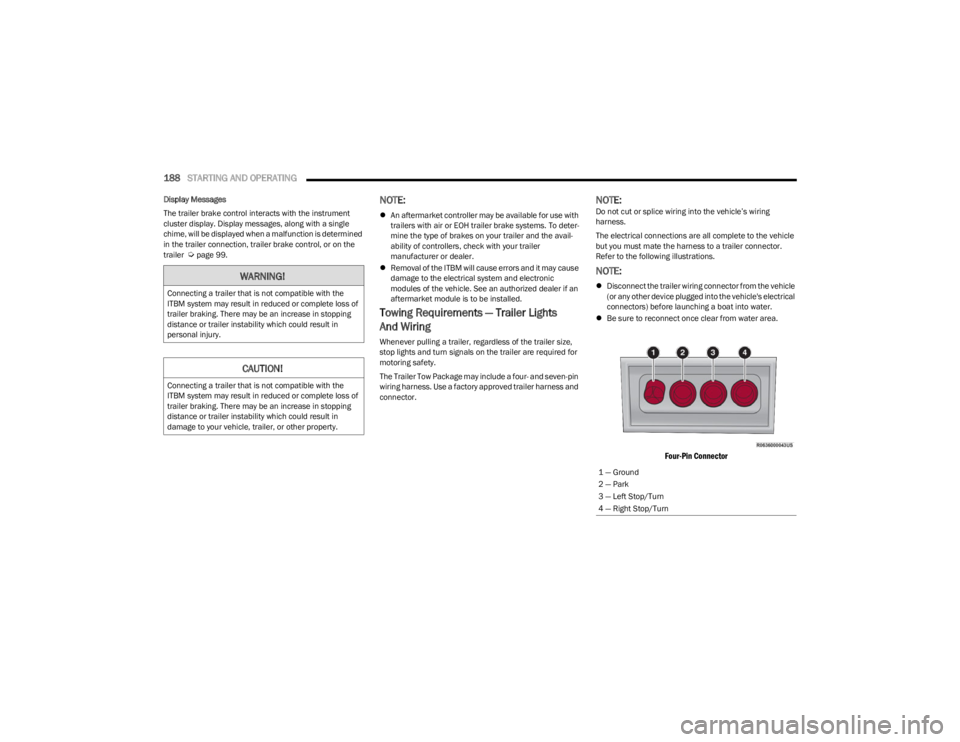
The Trailer Tow Package may include a four- and seven-pin
wiring harness. Use a factory approved trailer harness and
connector.
NOTE:Do not cut or splice wiring into the vehicle’s wiring
harness.
The electrical connections are all complete to the vehicle
but you must mate the harness to a trailer connector.
Refer to the following illustrations.
NOTE:
Disconnect the trailer wiring connector from the vehicle
(or any other device plugged into the vehicle's electrical
connectors) before launching a boat into water.
Be sure to reconnect once clear from water area.
Four-Pin Connector
WARNING!
Connecting a trailer that is not compatible with the
ITBM system may result in reduced or complete loss of
trailer braking. There may be an increase in stopping
distance or trailer instability which could result in
personal injury.
CAUTION!
Connecting a trailer that is not compatible with the
ITBM system may result in reduced or complete loss of
trailer braking. There may be an increase in stopping
distance or trailer instability which could result in
damage to your vehicle, trailer, or other property.
1 — Ground
2 — Park
3 — Left Stop/Turn
4 — Right Stop/Turn
23_WS_OM_EN_USC_t.book Page 188
Page 203 of 396
MULTIMEDIA201
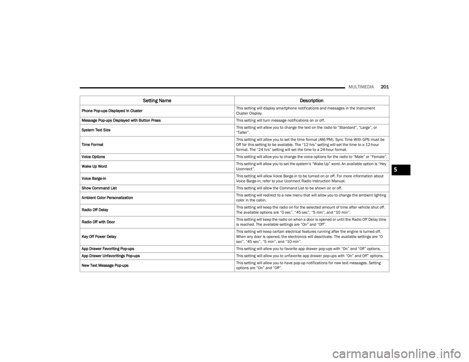
Phone Pop-ups Displayed In Cluster This setting will display smartphone notifications and messages in the Instrument
Cluster Display.
Message Pop-ups Displayed with Button Press This setting will turn message notifications on or off.
System Text Size This setting will allow you to change the text on the radio to “Standard”, “Large”, or
“Taller”.
Time Format This setting will allow you to set the time format (AM/PM). Sync Time With GPS must be
Off for this setting to be available. The “12 hrs” setting will set the time to a 12-hour
format. The “24 hrs” setting will set the time to a 24-hour format.
Voice Options This setting will allow you to change the voice options for the radio to “Male” or “Female”.
Wake Up Word This setting will allow you to set the system’s “Wake Up” word. An available option is “Hey
Uconnect”.
Voice Barge-in This setting will allow Voice Barge-in to be turned on or off. For more information about
Voice Barge-in, refer to your Uconnect Radio Instruction Manual.
Show Command List This setting will allow the Command List to be shown on or off.
Ambient Color Personalization This setting will redirect to a new menu that will allow you to change the ambient lighting
color in the cabin.
Radio Off Delay This setting will keep the radio on for the selected amount of time after vehicle shut off.
The available options are “0 sec”, “45 sec”, “5 min”, and “10 min”.
Radio Off with Door This setting will keep the radio on when a door is opened or until the Radio Off Delay time
is reached. The available settings are “On” and “Off”.
Key Off Power Delay This setting will keep certain electrical features running after the engine is turned off.
When any door is opened, the electronics will deactivate. The available settings are “0
sec”, “45 sec”, “5 min”, and “10 min”.
App Drawer Favoriting Pop-ups This setting will allow you to favorite app drawer pop-ups with “On” and “Off” options.
App Drawer Unfavoritings Pop-ups This setting will allow you to unfavorite app drawer pop-ups with “On” and Off” options.
New Text Message Pop-ups This setting will allow you to have pop-up notifications for new text messages. Setting
options are “On” and “Off”.
Setting Name
Description
5
23_WS_OM_EN_USC_t.book Page 201
Page 216 of 396

214MULTIMEDIA
Key Off Options
When the Key Off Options button is pressed on the touchscreen, the system displays the options related to vehicle shutoff. These settings will only activate when the ignition is set to
OFF.
NOTE:Depending on the vehicle’s options, feature settings may vary.
Setting Name Description
Easy Exit Seat This setting adjusts the seats to make exiting the vehicle easier.
Key Off Power Delay This setting will keep certain electrical features running after the engine is turned off.
When any door is opened, the electronics will deactivate. The available settings are
“0 sec”, “45 sec”, “5 min”, and “10 min”.
Headlight Off Delay This setting will allow you to set the amount of time the headlights remain on after the
vehicle has been turned off. The available settings are “0 sec”, “30 sec”, “60 sec”, and
“90 sec”.
Auto Entry/Exit Suspension This setting will turn the Auto Entry/Exit Suspension system on or off.
Radio Off Delay This setting will keep the radio on for the selected amount of time after vehicle shut off.
The available options are “0 sec”, “45 sec”, “5 min”, and “10 min”.
Radio Off With Door This setting will keep the radio on when a door is opened or until the Radio Off Delay time
is reached. The available settings are “On” and “Off”.
Windows With Key Fob This setting will allow you to control window function while the vehicle is off. The available
options are “On” and “Off”.
23_WS_OM_EN_USC_t.book Page 214
Page 266 of 396
264SAFETY
If the passenger seating position is equipped with an ALR
and is being used for normal usage, only pull the seat belt
webbing out far enough to comfortably wrap around the
occupant’s mid-section so as to not activate the ALR. If the
ALR is activated, you will hear a clicking sound as the seat
belt retracts. Allow the webbing to retract completely in
this case and then carefully pull out only the amount of
webbing necessary to comfortably wrap around the
occupant’s mid-section. Slide the latch plate into the
buckle until you hear a "click”.
In Automatic Locking Mode, the shoulder belt is
automatically pre-locked. The seat belt will still retract to
remove any slack in the shoulder belt. Use the Automatic
Locking Mode anytime a child restraint is installed in a
seating position that has a seat belt with this feature.
Children 12 years old and under should always be properly
restrained in the rear seat of a vehicle with a rear seat. How To Engage The Automatic Locking Mode
1. Buckle the combination lap and shoulder belt.
2. Grab the shoulder portion and pull downward until
the entire seat belt is extracted.
3. Allow the seat belt to retract. As the seat belt retracts, you will hear a clicking sound. This indicates the seat
belt is now in the Automatic Locking Mode.
How To Disengage The Automatic Locking Mode
Unbuckle the combination lap/shoulder belt and allow it
to retract completely to disengage the Automatic Locking
Mode and activate the vehicle sensitive (emergency)
locking mode.SUPPLEMENTAL RESTRAINT SYSTEMS
(SRS)
Some of the safety features described in this section may
be standard equipment on some models, or may be
optional equipment on others. If you are not sure, ask an
authorized dealer.
The air bag system must be ready to protect you in a
collision. The Occupant Restraint Controller (ORC)
monitors the internal circuits and interconnecting wiring
associated with the electrical Air Bag System
Components. Your vehicle may be equipped with the
following Air Bag System Components:
Air Bag System Components
Occupant Restraint Controller (ORC)
Air Bag Warning Light
Steering Wheel and Column
Instrument Panel
Knee Impact Bolsters
Driver and Front Passenger Air Bags
Seat Belt Buckle Switch
Supplemental Side Air Bags
Supplemental Knee Air Bags
Front and Side Impact Sensors
Seat Belt Pretensioners
Seat Track Position Sensors
Occupant Classification System
WARNING!
Never place a rear-facing child restraint in front of an
air bag. A deploying passenger front air bag can
cause death or serious injury to a child 12 years or
younger, including a child in a rear-facing child
restraint.
Never install a rear-facing child restraint in the front
seat of a vehicle. Only use a rear-facing child
restraint in the rear seat. If the vehicle does not have
a rear seat, do not transport a rear-facing child
restraint in that vehicle.
WARNING!
The seat belt assembly must be replaced if the
switchable Automatic Locking Retractor (ALR)
feature or any other seat belt function is not working
properly when checked according to the procedures
in the Service Manual.
Failure to replace the seat belt assembly could
increase the risk of injury in collisions.
Do not use the Automatic Locking Mode to restrain
occupants who are wearing the seat belt or children
who are using booster seats. The locked mode is only
used to install rear-facing or forward-facing child
restraints that have a harness for restraining the
child.
23_WS_OM_EN_USC_t.book Page 264
Page 274 of 396

272SAFETY
Vehicle damage by itself is not a good indicator of whether
or not Side Air Bags should have deployed.The Side Air
Bags will not deploy in all side collisions, including some
collisions at certain angles, or some side collisions that do
not impact the area of the passenger compartment. The
Side Air Bags may deploy during angled or offset frontal
collisions where the front air bags deploy.
Side Air Bags are a supplement to the seat belt restraint
system. Side Air Bags deploy in less time than it takes to
blink your eyes.
NOTE:Air bag covers may not be obvious in the interior trim, but
they will open during air bag deployment.
Rollover Events
Side Air Bags and seat belt pretensioners are designed to
activate in certain rollover events. The Occupant Restraint
Controller (ORC) determines whether deployment in a
particular rollover event is appropriate, based on the
severity and type of collision. Vehicle damage by itself is
not a good indicator of whether or not Side Air Bags and
seat belt pretensioners should have deployed.
The Side Air Bags and seat belt pretensioners will not
deploy in all rollover events. The rollover sensing system
determines if a rollover event may be in progress and
whether deployment is appropriate. In the event the vehicle experiences a rollover or near
rollover event, and deployment is appropriate, the rollover
sensing system will deploy the side air bags and seat belt
pretensioners on both sides of the vehicle.
The SABICs may help reduce the risk of partial or complete
ejection of vehicle occupants through side windows in
certain rollover or side impact events.
Air Bag System Components
NOTE:The Occupant Restraint Controller (ORC) monitors the
internal circuits and interconnecting wiring associated
with electrical Air Bag System Components listed below:
Occupant Restraint Controller (ORC)
Air Bag Warning Light
Steering Wheel and Column
Instrument Panel
Knee Impact Bolsters
Driver and Front Passenger Air Bags
Seat Belt Buckle Switch
Supplemental Side Air Bags
Supplemental Knee Air Bags
Front and Side Impact Sensors
Seat Belt Pretensioners
Seat Track Position Sensors
Occupant Classification SystemWARNING!
Occupants, including children, who are up against or
very close to Side Air Bags can be seriously injured or
killed. Occupants, including children, should never
lean on or sleep against the door, side windows, or
area where the side air bags inflate, even if they are
in an infant or child restraint.
Seat belts (and child restraints where appropriate)
are necessary for your protection in all collisions.
They also help keep you in position, away from an
inflating Side Air Bag. To get the best protection from
the Side Air Bags, occupants must wear their seat
belts properly and sit upright with their backs against
the seats. Children must be properly restrained in a
child restraint or booster seat that is appropriate for
the size of the child.
WARNING!
Side Air Bags need room to inflate. Do not lean
against the door or window. Sit upright in the center
of the seat.
Being too close to the Side Air Bags during deploy -
ment could cause you to be severely injured or killed.
Relying on the Side Air Bags alone could lead to more
severe injuries in a collision. The Side Air Bags work
with your seat belt to restrain you properly. In some
collisions, Side Air Bags won’t deploy at all. Always
wear your seat belt even though you have Side
Air Bags.
23_WS_OM_EN_USC_t.book Page 272
Page 294 of 396
292IN CASE OF EMERGENCY
SOS Call System Limitations
Vehicles sold in Mexico DO NOT have SOS Call system
capabilities.
SOS or other emergency line operators in Mexico may not
answer or respond to SOS system calls.
If the SOS Call system detects a malfunction, any of the
following may occur at the time the malfunction is
detected, and at the beginning of each ignition cycle:
The overhead console lights located within the ASSIST
and SOS buttons will continuously illuminate red.
The Device Screen will display the following message
“Vehicle device requires service. Please contact an
authorized dealer.”
An In-Vehicle Audio message will state “Vehicle device
requires service. Please contact an authorized dealer.”
Even if the SOS Call system is fully functional, factors
beyond FCA US LLC’s control may prevent or stop the SOS
Call system operation. These include, but are not limited
to, the following factors:
The ignition is in the OFF position
The vehicle’s electrical systems are not intact
The SOS Call system software and/or hardware are
damaged during a crash
The vehicle battery loses power or becomes discon -
nected during a vehicle crash
LTE (voice/data) or 4G (data) network and/or Global
Positioning Satellite signals are unavailable or
obstructed
Equipment malfunction at the SOS operator facility
Operator error by the SOS operator
LTE (voice/data) or 4G (data) network congestion
Weather
Buildings, structures, geographic terrain, or tunnels
NOTE:
Your vehicle may be transmitting data as authorized by
the subscriber.
Never place anything on or near the vehicle’s LTE
(voice/data) or 4G (data) and GPS antennas. You could
prevent LTE (voice/data) or 4G (data) and GPS signal
reception, which can prevent your vehicle from placing
an emergency call. An operable LTE (voice/data) or 4G
(data) network connection and a GPS signal is required
for the SOS Call system to function properly.
NOTE:Changes or modifications not expressly approved by the
party responsible for compliance could void the user's
authority to operate the equipment.
The SOS Call system is embedded into the vehicle’s
electrical system. Do not add aftermarket electrical
equipment to the vehicle’s electrical system. This
may prevent your vehicle from sending a signal to
initiate an emergency call. To avoid interference that
can cause the SOS Call system to fail, never add
aftermarket equipment (e.g., two-way mobile radio,
CB radio, data recorder, etc.) to your vehicle’s elec -
trical system or modify the antennas on your vehicle.
IF YOUR VEHICLE LOSES BATTERY POWER FOR ANY
REASON (INCLUDING DURING OR AFTER AN ACCI -
DENT), THE UCONNECT FEATURES, APPS AND
SERVICES, AMONG OTHERS, WILL NOT OPERATE.
Modifications to any part of the SOS Call system
could cause the air bag system to fail when you need
it. You could be injured if the air bag system is not
there to help protect you.
WARNING!
WARNING!
Ignoring the overhead console light could mean you
will not have SOS Call services. If the overhead
console light is illuminated, have an authorized
dealer service the SOS Call system immediately.
The Occupant Restraint Control module turns on the
air bag Warning Light on the instrument panel if a
malfunction in any part of the system is detected. If
the Air Bag Warning Light is illuminated, have an
authorized dealer service the Occupant Restraint
Control system immediately.
WARNING!
ALWAYS obey traffic laws and pay attention to the road.
ALWAYS drive safely with your hands on the steering
wheel. You have full responsibility and assume all risks
related to the use of the features and applications in
this vehicle. Only use the features and applications
when it is safe to do so. Failure to do so may result in an
accident involving serious injury or death.
23_WS_OM_EN_USC_t.book Page 292
Page 302 of 396

300IN CASE OF EMERGENCY
12. Lower the jack to the fully closed position.
13. Return the Jack and tools back into the jack storage
bin. Reinstall the jack storage cover by firmly pushing
down until the clips lock into position.
14. After 25 miles (40 km), check the lug nut torque with a torque wrench to ensure that all lug nuts are
properly seated against the wheel.
15. Have the road wheel and tire repaired as soon as possible and properly secure the spare tire, jack and
tool kit.
NOTE:Do not drive with the spare tire installed for more than
50 miles (80 km) at a max speed of 50 mph (80 km/h).
JUMP STARTING
If your vehicle has a discharged battery, it can be jump
started using a set of jumper cables and a battery in
another vehicle, or by using a portable battery booster
pack. Jump starting can be dangerous if done improperly,
so please follow the procedures in this section carefully.
NOTE:When using a portable battery booster pack, follow the
manufacturer's operating instructions and precautions.
PREPARATIONS FOR JUMP START
The battery in your vehicle is located in the front of the
engine compartment, behind the left headlight assembly.
Positive (+) Jump Starting Post
NOTE:The positive (+) battery post may be covered with a
protective cap. Lift up on the cap to gain access to the
positive battery post. Do not jump off fuses. Only jump
directly off positive post which has a positive (+) symbol on
or around the post.
See the following steps to prepare for jump starting:
1. Apply the parking brake, shift the automatic transmission into PARK (P) and turn the ignition OFF.
2. Turn off the heater, radio, and all electrical accessories.
3. If using another vehicle to jump start the battery, park the vehicle within the jumper cables’ reach, apply the
parking brake and make sure the ignition is OFF.
NOTE:Be sure that the disconnected cable ends do not touch
each other, or either vehicle, until properly connected for
jump starting.
WARNING!
Do not attempt jump starting if the battery is frozen. It
could rupture or explode and cause personal injury.
CAUTION!
Do not use a portable battery booster pack or any other
booster source with a system voltage greater than
12 Volts or damage to the battery, starter motor,
alternator or electrical system may occur.
WARNING!
Do not allow vehicles to touch each other as this could
establish a ground connection and personal injury
could result.
23_WS_OM_EN_USC_t.book Page 300
Page 303 of 396
IN CASE OF EMERGENCY301
JUMP STARTING PROCEDURE
NOTE:Make sure at all times that unused ends of jumper cables
are not contacting each other or either vehicle while
making connections.
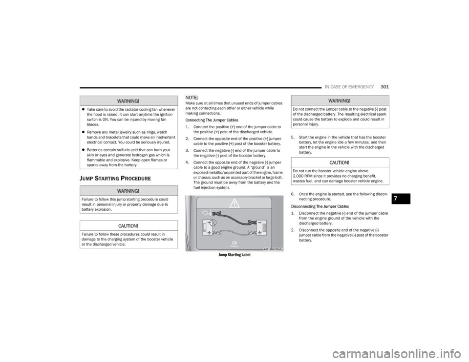
Connecting The Jumper Cables
1. Connect the positive
(+) end of the jumper cable to
the positive (+)
post of the discharged vehicle.
2. Connect the opposite end of the positive (+) jumper
cable to the positive (+) post of the booster battery.
3. Connect the negative (-) end of the jumper cable to
the negative (-) post of the booster battery.
4. Connect the opposite end of the negative (-) jumper
cable to a good engine ground. A “ground” is an
exposed metallic/unpainted part of the engine, frame
or chassis, such as an accessory bracket or large bolt.
The ground must be away from the battery and the
fuel injection system.
Jump Starting Label
5. Start the engine in the vehicle that has the booster battery, let the engine idle a few minutes, and then
start the engine in the vehicle with the discharged
battery.
6. Once the engine is started, see the following discon- necting procedure.
Disconnecting The Jumper Cables
1. Disconnect the negative
(-)
end of the jumper cable
from the engine ground of the vehicle with the
discharged battery.
2. Disconnect the opposite end of the negative (-)
jumper cable from the negative (-) post of the booster
battery.
WARNING!
Take care to avoid the radiator cooling fan whenever
the hood is raised. It can start anytime the ignition
switch is ON. You can be injured by moving fan
blades.
Remove any metal jewelry such as rings, watch
bands and bracelets that could make an inadvertent
electrical contact. You could be seriously injured.
Batteries contain sulfuric acid that can burn your
skin or eyes and generate hydrogen gas which is
flammable and explosive. Keep open flames or
sparks away from the battery.
WARNING!
Failure to follow this jump starting procedure could
result in personal injury or property damage due to
battery explosion.
CAUTION!
Failure to follow these procedures could result in
damage to the charging system of the booster vehicle
or the discharged vehicle.
WARNING!
Do not connect the jumper cable to the negative (-) post
of the discharged battery. The resulting electrical spark
could cause the battery to explode and could result in
personal injury.
CAUTION!
Do not run the booster vehicle engine above
2,000 RPM since it provides no charging benefit,
wastes fuel, and can damage booster vehicle engine.
7
23_WS_OM_EN_USC_t.book Page 301