stop start JEEP WAGONEER 2023 Workshop Manual
[x] Cancel search | Manufacturer: JEEP, Model Year: 2023, Model line: WAGONEER, Model: JEEP WAGONEER 2023Pages: 396, PDF Size: 15.17 MB
Page 175 of 396
STARTING AND OPERATING173
(Continued)
Level 1 Warnings:
Yellow telltale in the instrument cluster display
Yellow highlights around the detected
pedestrian/animal
Occurs when the vehicle is moving at speeds greater
than 8 mph (13 km/h) and the target is in or
approaching the vehicle path
Level 2 Warnings:
Red telltale in the instrument cluster display
Red highlights around the detected pedestrian/animal
Occurs when the vehicle is moving at speeds greater
than 8 mph (13 km/h) and a collision with the detected
pedestrian/animal is possible
The pedestrian/animal is directly in the vehicle path,
close to the headlight area
A video pop-up will display when there is a target
detected and the instrument cluster display is not
showing the Night Vision page
A chime will sound for a Level 2 Warning detection
event
Only one telltale can be displayed at a time based upon
priority.
The priority order of the warnings from highest to lowest is:
1. Pedestrian Warning Level 2
2. Animal Warning Level 2
3. Pedestrian Warning Level 1
4. Animal Warning Level 1
Level 2 Warnings may display in the Head Up Display
(if equipped).
NOTE:If the vehicle is stopped, or slowing down, all Level 2
warnings become Level 1 warnings.
You can enable or disable the warnings within the
Uconnect system
Úpage 197.
If the warnings are off, the telltales, chimes, and warning
messages will all be off. Pedestrians and animals can still
be detected by the system, but there will be no warnings. The Night Vision alert status telltale will be gray
when the warnings are suppressed. The telltale
will also turn gray to indicate that the alerts are
suppressed due to environmental factors (e.g.
daylight hours, external temperature is greater than 86°F
(30°C)) or if the gear selector is in REVERSE. When the
Night Vision alerts are active, the telltale will be green
Úpage 108.
Camera Washers
When the front window washer is activated, the Night
Vision camera will also be washed
Úpage 63.DETECTION RANGE
The system can detect people 4 ft (1.25 m) tall or greater
in the upright position. The system can also detect
animals that are four-legged and 3 ft (1 m) tall or greater
in the upright position.
The detection distance for the system is between 26 ft
(8 m) and 328 ft (100 m) from the front of the vehicle.WARNING!
Do not jerk the steering wheel in response to a
warning.
Never attempt to swerve around animals if doing so
would endanger you or others.
Do not stare at the image while driving. You could
crash and you or others could be injured.
The Night Vision system only provides alerts to
objects of interest and cannot serve as a substitute
for the driver’s personal judgment. The warnings are
meant to direct your attention to the detected
objects, but the Night Vision system does not auto -
matically brake the vehicle and may not provide a
warning with enough time to help avoid a crash.
Warnings are only provided if a pedestrian or large
animal is detected by the system.
It is always the driver’s responsibility to be attentive
of road, traffic, and weather conditions, vehicle
speed, distance to the vehicle ahead, and most
importantly, brake operation, to ensure safe opera -
tion of the vehicle under all road conditions. Your
complete attention is always required while driving to
maintain safe control of your vehicle.
WARNING!
4
23_WS_OM_EN_USC_t.book Page 173
Page 178 of 396
176STARTING AND OPERATING
Top View Plus Front View
The Front View will show you what is
immediately in front of the vehicle and is
always paired with the Top View of the vehicle.
Front Cross Path View Pressing the Front Cross Path button will give
the driver a wider angle view of the front
camera system. The Top View will be disabled
when this is selected.
Back Up Camera View Pressing the Back Up Camera button will
provide a full screen rear view with Zoom View.
NOTE:If the Rear View Camera view was selected through the
Surround View Camera menu, exiting out of the Rear View
screen will return to the Surround View Camera menu. If
the Back Up Camera was manually activated through the
Controls menu of the Uconnect system, exiting out of the
display screen will return to the Controls menu.
Deactivation
The system can be deactivated under the following
conditions:
The speed of the vehicle is greater than 8 mph
(13 km/h).
The vehicle is shifted into PARK.
The vehicle is in any gear other than REVERSE and the
touchscreen X button is pressed.
The camera delay system is turned off manually
through Uconnect Settings
Úpage 197.
Camera Washers
When the rear window washer is activated, the rear Back
Up and digital rearview mirror (if equipped) cameras are
also washed
Úpage 64.
When the front window washer is activated, the front
cameras will also be washed
Úpage 63.
NOTE:
If snow, ice, mud, or any foreign substance builds up on
the camera lenses, clean the lenses, rinse with water,
and dry with a soft cloth. Do not cover the lenses.
If a malfunction with the system has occurred, see an
authorized dealer.ZOOM VIEW
When the Rear View Camera image is being displayed, and
the vehicle speed is below 8 mph (13 km/h) while in any
gear selector position, Zoom View is available. By pressing the “magnifying glass” icon in the
upper left of the display screen, the image will
zoom in to two times the standard view.
Pressing the icon a second time will return the
view to the standard Back Up Camera display.
When Zoom View is selected while the vehicle
is in
REVERSE, then shifted to DRIVE, the camera delay view
will display the standard Back Up Camera view. If the
vehicle is then returned to REVERSE gear from DRIVE,
the Zoom View selection will automatically resume.
Shifting to NEUTRAL from any gear will maintain the
selected view (Zoom or Standard) as long as the vehicle
is below 8 mph (13 km/h).
WARNING!
Drivers must be careful when backing up even when
using the Surround View Camera. Always check
carefully behind your vehicle, and be sure to check for
pedestrians, animals, other vehicles, obstructions, or
blind spots before backing up. You are responsible for
the safety of your surroundings and must continue to
pay attention while backing up. Failure to do so can
result in serious injury or death.
CAUTION!
To avoid vehicle damage, Surround View should only
be used as a parking aid. The Surround View camera
is unable to view every obstacle or object in your
drive path.
To avoid vehicle damage, the vehicle must be driven
slowly when using Surround View to be able to stop
in time when an obstacle is seen. It is recommended
that the driver look frequently over his/her shoulder
when using Surround View.
23_WS_OM_EN_USC_t.book Page 176
Page 188 of 396
186STARTING AND OPERATING
Towing Requirements — Tires
Do not attempt to tow a trailer while using a compact
spare tire.
Do not drive more than 50 mph (80 km/h) when towing
while using a full-size spare tire.
Proper tire inflation pressures are essential to the safe
and satisfactory operation of your vehicle.
Check the trailer tires for proper tire inflation pressures
before trailer usage.
Check for signs of tire wear or visible tire damage
before towing a trailer.
Replacing tires with a higher load carrying capacity will
not increase the vehicle's GVWR and GAWR limits.
For further information
Úpage 349.
Towing Requirements — Trailer Brakes
Do not interconnect the hydraulic brake system or
vacuum system of your vehicle with that of the trailer.
This could cause inadequate braking and possible
personal injury.
An electronically actuated trailer brake controller is
required when towing a trailer with electronically actu -
ated brakes. When towing a trailer equipped with a
hydraulic surge actuated brake system, an electronic
brake controller is not required.
Trailer brakes are recommended for trailers over
1,000 lb (453 kg) and required for trailers in excess of
2,000 lb (907 kg).
Integrated Trailer Brake Module (ITBM) —
If Equipped
Your vehicle may have an ITBM for Electric and Electric
Over Hydraulic (EOH) trailer brakes. The controller is
located below the instrument panel on the right side of the
steering column.
NOTE:This module has been designed and verified with electric
trailer brakes and EOH systems. Some previous EOH
systems may not be compatible with ITBM.
Total weight must be distributed between the tow
vehicle and the trailer such that the following four
ratings are not exceeded :
GVWR
GTW
GAWR
Tongue weight rating for the trailer hitch utilized
WARNING!
WARNING!
Do not connect trailer brakes to your vehicle's
hydraulic brake lines. It can overload your brake
system and cause it to fail. You might not have
brakes when you need them and could have an acci -
dent.
Towing any trailer will increase your stopping
distance. When towing, you should allow for addi -
tional space between your vehicle and the vehicle in
front of you. Failure to do so could result in an
accident.
CAUTION!
If the trailer weighs more than 1,000 lb (453 kg)
loaded, it should have its own brakes and they should
be of adequate capacity. Failure to do this could lead to
accelerated brake lining wear, higher brake pedal
effort, and longer stopping distances.
23_WS_OM_EN_USC_t.book Page 186
Page 190 of 396
188STARTING AND OPERATING
Display Messages
The trailer brake control interacts with the instrument
cluster display. Display messages, along with a single
chime, will be displayed when a malfunction is determined
in the trailer connection, trailer brake control, or on the
trailer
Úpage 99.
NOTE:
An aftermarket controller may be available for use with
trailers with air or EOH trailer brake systems. To deter -
mine the type of brakes on your trailer and the avail -
ability of controllers, check with your trailer
manufacturer or dealer.
Removal of the ITBM will cause errors and it may cause
damage to the electrical system and electronic
modules of the vehicle. See an authorized dealer if an
aftermarket module is to be installed.
Towing Requirements — Trailer Lights
And Wiring
Whenever pulling a trailer, regardless of the trailer size,
stop lights and turn signals on the trailer are required for
motoring safety.
The Trailer Tow Package may include a four- and seven-pin
wiring harness. Use a factory approved trailer harness and
connector.
NOTE:Do not cut or splice wiring into the vehicle’s wiring
harness.
The electrical connections are all complete to the vehicle
but you must mate the harness to a trailer connector.
Refer to the following illustrations.
NOTE:
Disconnect the trailer wiring connector from the vehicle
(or any other device plugged into the vehicle's electrical
connectors) before launching a boat into water.
Be sure to reconnect once clear from water area.
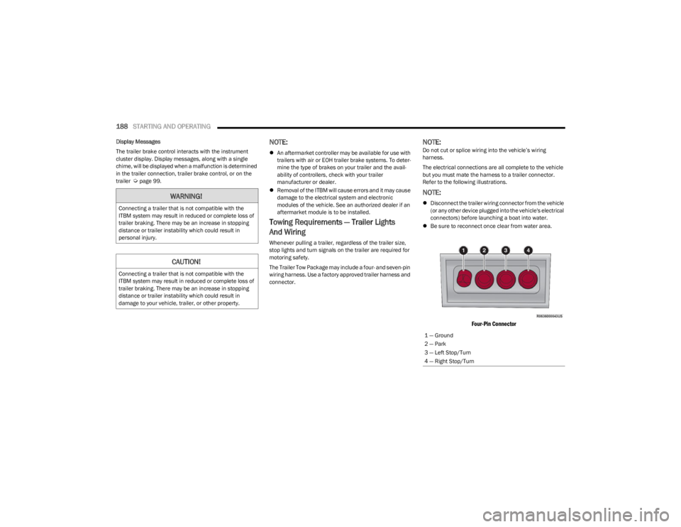
Four-Pin Connector
WARNING!
Connecting a trailer that is not compatible with the
ITBM system may result in reduced or complete loss of
trailer braking. There may be an increase in stopping
distance or trailer instability which could result in
personal injury.
CAUTION!
Connecting a trailer that is not compatible with the
ITBM system may result in reduced or complete loss of
trailer braking. There may be an increase in stopping
distance or trailer instability which could result in
damage to your vehicle, trailer, or other property.
1 — Ground
2 — Park
3 — Left Stop/Turn
4 — Right Stop/Turn
23_WS_OM_EN_USC_t.book Page 188
Page 191 of 396
STARTING AND OPERATING189
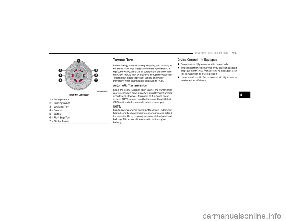
Seven-Pin Connector
TOWING TIPS
Before towing, practice turning, stopping, and backing up
the trailer in an area located away from heavy traffic. If
equipped with Quadra-Lift air suspension, the automatic
Entry/Exit feature may be disabled through the Uconnect
Touchscreen Radio to prevent vehicle and trailer
movement when gear selector is moved to PARK.
Automatic Transmission
Select the DRIVE (D) range when towing. The transmission
controls include a drive strategy to avoid frequent shifting
when towing. However, if frequent shifting does occur
while in DRIVE, you can use the Electronic Range Select
(ERS) shift control to manually select a lower gear.
NOTE:Using a lower gear while operating the vehicle under heavy
loading conditions, will improve performance and extend
transmission life by reducing excessive shifting and heat
build-up. This action will also provide better engine
braking.
Cruise Control — If Equipped
Do not use on hilly terrain or with heavy loads.
When using the Cruise Control, if you experience speed
drops greater than 10 mph (16 km/h), disengage until
you can get back to cruising speed.
Use Cruise Control in flat terrain and with light loads to
maximize fuel efficiency.
1 — Backup Lamps
2 — Running Lamps
3 — Left Stop/Turn
4 — Ground
5 — Battery
6 — Right Stop/Turn
7 — Electric Brakes
4
23_WS_OM_EN_USC_t.book Page 189
Page 194 of 396
192STARTING AND OPERATING
Use the following procedure to prepare your vehicle for
recreational towing:
1. Bring the vehicle to a complete stop on level ground,
with the engine running.
2. Press and hold the brake pedal.
3. Shift the transmission into NEUTRAL.
4. If vehicle is equipped with Quadra-Lift air suspension, ensure the vehicle is set to Normal Ride Height.
NOTE:
Steps 1 through 4 are requirements that must be
met before pushing the N (Neutral) button, and
must continue to be met until the shift has been
completed. If any of these requirements are not
met before pushing the N (Neutral) button or are
no longer met during the shift, then the N (Neutral)
indicator light will flash continuously until all
requirements are met or until the N (Neutral)
button is released.
The ignition must be in the ON/RUN position for a
shift to take place and for the position indicator
lights to be operable. If the ignition is not in the
ON/RUN position, the shift will not take place and
no position indicator lights will be on or flashing.
A flashing N (Neutral) position indicator light indi-
cates that shift requirements have not been met.
If the vehicle is equipped with Quadra-Lift air
suspension, the engine should be started and left
running for a minimum of 60 seconds (with all the
doors closed) at least once every 24 hours. This
process allows the air suspension to adjust the
vehicle’s ride height to compensate for tempera -
ture effects.
Engaging/disengaging of the Electric Park Brake
requires the ignition to be in the ON/RUN position.
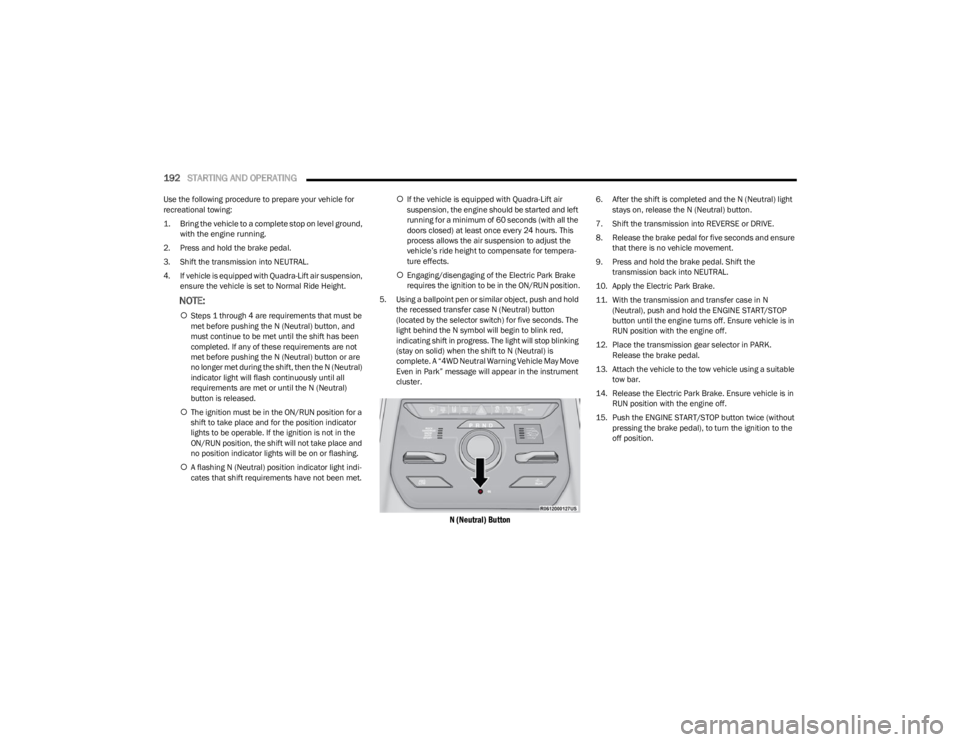
5. Using a ballpoint pen or similar object, push and hold the recessed transfer case N (Neutral) button
(located by the selector switch) for five seconds. The
light behind the N symbol will begin to blink red,
indicating shift in progress. The light will stop blinking
(stay on solid) when the shift to N (Neutral) is
complete. A “4WD Neutral Warning Vehicle May Move
Even in Park” message will appear in the instrument
cluster.
N (Neutral) Button
6. After the shift is completed and the N (Neutral) light stays on, release the N (Neutral) button.
7. Shift the transmission into REVERSE or DRIVE.
8. Release the brake pedal for five seconds and ensure that there is no vehicle movement.
9. Press and hold the brake pedal. Shift the transmission back into NEUTRAL.
10. Apply the Electric Park Brake.
11. With the transmission and transfer case in N (Neutral), push and hold the ENGINE START/STOP
button until the engine turns off. Ensure vehicle is in
RUN position with the engine off.
12. Place the transmission gear selector in PARK. Release the brake pedal.
13. Attach the vehicle to the tow vehicle using a suitable tow bar.
14. Release the Electric Park Brake. Ensure vehicle is in RUN position with the engine off.
15. Push the ENGINE START/STOP button twice (without pressing the brake pedal), to turn the ignition to the
off position.
23_WS_OM_EN_USC_t.book Page 192
Page 195 of 396
STARTING AND OPERATING193
Shifting Out Of N (Neutral)
Use the following procedure to prepare your vehicle for
normal usage:
1. Bring the vehicle to a complete stop, leaving it
connected to the tow vehicle.
2. Apply the Electric Park Brake.
3. Start the engine.
NOTE:
Steps 1 through 5 are requirements that must be
met before pushing the N (Neutral) button, and
must continue to be met until the shift has been
completed. If any of these requirements are not
met before pushing the N (Neutral) button or are
no longer met during the shift, the N (Neutral) indi -
cator light will flash continuously until all require -
ments are met or until the N (Neutral) button is
released.
The ignition must be in the ON/RUN position for a
shift to take place and for the position indicator
lights to be operable. If the ignition is not in the
ON/RUN position, the shift will not take place and
no position indicator lights will be on or flashing.
A flashing N (Neutral) position indicator light indi-
cates that shift requirements have not been met.
4. Press and hold the brake pedal.
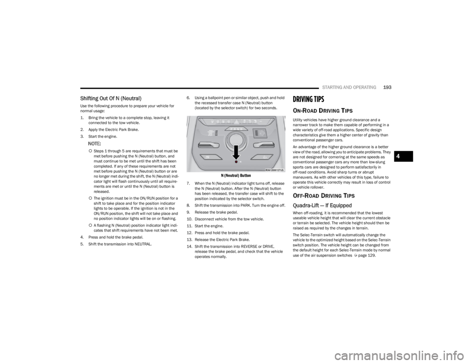
5. Shift the transmission into NEUTRAL. 6. Using a ballpoint pen or similar object, push and hold
the recessed transfer case N (Neutral) button
(located by the selector switch) for two seconds.
N (Neutral) Button
7. When the N (Neutral) indicator light turns off, release the N (Neutral) button. After the N (Neutral) button
has been released, the transfer case will shift to the
position indicated by the selector switch.
8. Shift the transmission into PARK. Turn the engine off.
9. Release the brake pedal.
10. Disconnect vehicle from the tow vehicle.
11. Start the engine.
12. Press and hold the brake pedal.
13. Release the Electric Park Brake.
14. Shift the transmission into REVERSE or DRIVE, release the brake pedal, and check that the vehicle
operates normally.
DRIVING TIPS
ON-ROAD DRIVING TIPS
Utility vehicles have higher ground clearance and a
narrower track to make them capable of performing in a
wide variety of off-road applications. Specific design
characteristics give them a higher center of gravity than
conventional passenger cars.
An advantage of the higher ground clearance is a better
view of the road, allowing you to anticipate problems. They
are not designed for cornering at the same speeds as
conventional passenger cars any more than low-slung
sports cars are designed to perform satisfactorily in
off-road conditions. Avoid sharp turns or abrupt
maneuvers. As with other vehicles of this type, failure to
operate this vehicle correctly may result in loss of control
or vehicle rollover.
OFF-ROAD DRIVING TIPS
Quadra-Lift — If Equipped
When off-roading, it is recommended that the lowest
useable vehicle height that will clear the current obstacle
or terrain be selected. The vehicle height should then be
raised as required by the changes in terrain.
The Selec-Terrain switch will automatically change the
vehicle to the optimized height based on the Selec-Terrain
switch position. The vehicle height can be changed from
the default height for each Selec-Terrain mode by normal
use of the air suspension switches
Úpage 129.
4
23_WS_OM_EN_USC_t.book Page 193
Page 197 of 396
STARTING AND OPERATING195
If you stall or begin to lose forward motion while climbing
a steep hill, allow your vehicle to come to a stop and
immediately apply the brakes. Restart the engine, and
shift into REVERSE (R). Back slowly down the hill, allowing
the compression braking of the engine to help regulate
your speed. If the brakes are required to control vehicle
speed, apply them lightly and avoid locking or skidding the
tires.
Remember, never drive diagonally across a hill. Always
drive straight up or down.
If the wheels start to slip as you approach the crest of a
hill, ease off the accelerator and maintain forward motion
by turning the front wheels slowly. This may provide a fresh
“bite” into the surface and will usually provide traction to
complete the climb.Traction Downhill
When descending mountains or hills, use Hill Descent
Control or Selec-Speed Control to avoid repeated heavy
braking.
If not equipped with Hill Descent Control or Selec-Speed
Control use the following procedure:
Shift the transmission into a low gear, and the transfer
case into 4WD LOW range. Let the vehicle go slowly down
the hill with all four wheels turning against engine
compression drag. This will permit you to control the
vehicle speed and direction.
When descending mountains or hills, repeated braking
can cause brake fade with loss of braking control. Avoid
repeated heavy braking by downshifting the transmission
whenever possible.
After Driving Off-Road
Off-road operation puts more stress on your vehicle than
does most on-road driving. After going off-road, it is always
a good idea to check for damage. That way you can get any
problems taken care of right away and have your vehicle
ready when you need it.
Completely inspect the underbody of your vehicle.
Check tires, body structure, steering, suspension, and
exhaust system for damage.
Inspect the radiator for mud and debris and clean as
required.
Check threaded fasteners for looseness, particularly
on the chassis, drivetrain components, steering, and
suspension. Retighten them, if required, and torque to
the values specified in the Service Manual.
Check for accumulations of plants or brush. These
things could be a fire hazard. They might hide damage
to fuel lines, brake hoses, axle pinion seals, and
propeller shafts.
After extended operation in mud, sand, water, or
similar dirty conditions, have the radiator, fan, brake
rotors, wheels, brake linings, and axle yokes inspected
and cleaned as soon as possible.
If you experience unusual vibration after driving in
mud, slush or similar conditions, check the wheels for
impacted material. Impacted material can cause a
wheel imbalance and freeing the wheels of it will
correct the situation.
WARNING!
If the engine stalls, you lose forward motion, or cannot
make it to the top of a steep hill or grade, never attempt
to turn around. To do so may result in tipping and rolling
the vehicle. Always back carefully straight down a hill in
REVERSE gear. Never back down a hill in NEUTRAL
using only the brake.
WARNING!
Abrasive material in any part of the brakes may cause
excessive wear or unpredictable braking. You might not
have full braking power when you need it to prevent a
collision. If you have been operating your vehicle in dirty
conditions, get your brakes checked and cleaned as
necessary.
4
23_WS_OM_EN_USC_t.book Page 195
Page 241 of 396
239
(Continued)
SAFETY
SAFETY FEATURES
ANTI-LOCK BRAKE SYSTEM (ABS)
The ABS provides increased vehicle stability and brake
performance under most braking conditions. The system
automatically prevents wheel lock and enhances vehicle
control during braking.
The ABS performs a self-check cycle to ensure that the
ABS is working properly each time the vehicle is started
and driven. During this self-check, you may hear a slight
clicking sound as well as some related motor noises.
The ABS is activated during braking when the system
detects one or more wheels are beginning to lock. Road
conditions such as ice, snow, gravel, bumps, railroad
tracks, loose debris, or panic stops may increase the
likelihood of ABS activation(s).
You also may experience the following normal
characteristics when the ABS activates:
ABS motor noise or clicking sounds (you may continue
to hear for a short time after the stop).
Brake pedal pulsations.
A slight drop of the brake pedal at the end of the stop. The ABS is designed to function with the Original
Equipment Manufacturer (OEM) tires. Modification may
result in degraded ABS performance.
Anti-Lock Brake System (ABS) Warning
Light
The yellow ABS Warning Light will turn on when the ignition
is placed in the ON/RUN mode and may stay on for as long
as four seconds.
If the ABS Warning Light remains on or comes on while
driving, it indicates that the anti-lock portion of the brake
system is not functioning and that service is required.
However, the conventional brake system will continue to
operate normally if the ABS Warning Light is on.
If the ABS Warning Light is on, the brake system should be
serviced as soon as possible to restore the benefits of
Anti-Lock Brakes. If the ABS Warning Light does not come
on when the ignition is placed in the ON/RUN mode, have
the light repaired as soon as possible.
WARNING!
The ABS contains sophisticated electronic equip -
ment that may be susceptible to interference caused
by improperly installed or high output radio transmit -
ting equipment. This interference can cause possible
loss of anti-lock braking capability. Installation of
such equipment should be performed by qualified
professionals.
Pumping of the Anti-Lock Brakes will diminish their
effectiveness and may lead to a collision. Pumping
makes the stopping distance longer. Just press firmly
on your brake pedal when you need to slow down or
stop.
The ABS cannot prevent the natural laws of physics
from acting on the vehicle, nor can it increase
braking or steering efficiency beyond that afforded
by the condition of the vehicle brakes and tires or the
traction afforded.
The ABS cannot prevent collisions, including those
resulting from excessive speed in turns, following
another vehicle too closely, or hydroplaning.
The capabilities of an ABS equipped vehicle must
never be exploited in a reckless or dangerous
manner that could jeopardize the user’s safety or the
safety of others.
WARNING!
6
23_WS_OM_EN_USC_t.book Page 239
Page 243 of 396
SAFETY241
ELECTRONIC BRAKE CONTROL (EBC)
S
YSTEM
Your vehicle is equipped with an advanced EBC system.
This system includes the Anti-Lock Brake System (ABS),
Brake Assist System (BAS), Electronic Brake Force
Distribution (EBD), Electronic Stability Control (ESC),
Electronic Roll Mitigation (ERM), Hill Start Assist (HSA),
Intersection Collision Assist (ICA), and Traction Control
System (TCS). These systems work together to enhance
both vehicle stability and control in various driving
conditions.
Your vehicle may also be equipped with Dynamic Steering
Torque (DST), Rain Brake Support (RBS), Ready Alert
Braking (RAB), and Trailer Sway Control (TSC).
Brake Assist System (BAS)
The BAS is designed to optimize the vehicle’s braking
capability during emergency braking maneuvers. The
system detects an emergency braking situation by sensing
the rate and amount of brake application and then applies
optimum pressure to the brakes. This can help reduce
braking distances. The BAS complements the Anti-Lock
Brake System (ABS). Applying the brakes very quickly
results in the best BAS assistance. To receive the benefit
of the system, you must apply continuous braking
pressure during the stopping sequence (do not “pump”
the brakes). Do not reduce brake pedal pressure unless
braking is no longer desired. Once the brake pedal is
released, the BAS is deactivated.
Brake System Warning Light
The red Brake System Warning Light will turn on when the
ignition is placed in the ON/RUN mode and may stay on for
as long as four seconds.
If the Brake System Warning Light remains on or comes on
while driving, it indicates that the brake system is not
functioning properly and that immediate service is
required. If the Brake System Warning Light does not
come on when the ignition is placed in the ON/RUN mode,
have the light repaired as soon as possible.
Electronic Brake Force Distribution (EBD)
EBD manages the distribution of the braking torque
between the front and rear axles by limiting braking
pressure to the rear axle. This is done to prevent
overslip of the rear wheels to avoid vehicle instability, and
to prevent the rear axle from entering ABS before the
front axle.
Electronic Roll Mitigation (ERM)
ERM anticipates the potential for wheel lift by monitoring
the driver’s steering wheel input and the speed of the
vehicle. When ERM determines that the rate of change of
the steering wheel angle and vehicle’s speed are
sufficient to potentially cause wheel lift, it then applies the
appropriate brake and may also reduce engine power to
lessen the chance that wheel lift will occur. ERM can only
reduce the chance of wheel lift occurring during severe or
evasive driving maneuvers; it cannot prevent wheel lift
due to other factors, such as road conditions, leaving the
roadway, or striking objects or other vehicles.
NOTE:
ERM is disabled any time the ESC is in “Full Off” mode (if
equipped). See
Úpage 242 for a complete explanation of
the available ESC modes.
WARNING!
The Brake Assist System (BAS) cannot prevent the
natural laws of physics from acting on the vehicle, nor
can it increase the traction afforded by prevailing road
conditions. BAS cannot prevent collisions, including
those resulting from excessive speed in turns, driving
on very slippery surfaces, or hydroplaning. The
capabilities of a BAS-equipped vehicle must never be
exploited in a reckless or dangerous manner, which
could jeopardize the user's safety or the safety of
others.
WARNING!
Many factors, such as vehicle loading, road conditions
and driving conditions, influence the chance that wheel
lift or rollover may occur. ERM cannot prevent all wheel
lift or rollovers, especially those that involve leaving the
roadway or striking objects or other vehicles. The
capabilities of an ERM-equipped vehicle must never be
exploited in a reckless or dangerous manner which
could jeopardize the user's safety or the safety of
others.
6
23_WS_OM_EN_USC_t.book Page 241