sensor JEEP WAGONEER 2023 Owners Manual
[x] Cancel search | Manufacturer: JEEP, Model Year: 2023, Model line: WAGONEER, Model: JEEP WAGONEER 2023Pages: 396, PDF Size: 15.17 MB
Page 6 of 396

4
STARTING AND OPERATING
STARTING THE ENGINE ................................................. 119
Automatic Transmission ........................................... 119
Keyless Enter ‘n Go™ — Ignition .............................. 119
Normal Starting ...................................................... 119AutoPark .................................................................... 120Extended Park Starting............................................. 121
If Engine Fails To Start ............................................. 121
Cold Weather Operation
(Below –22°F Or −30°C) ........................................ 122After Starting ............................................................. 122Turbocharger “Cool Down” —
3.0L Engine Only ....................................................... 122
ENGINE BLOCK HEATER — IF EQUIPPED ..................... 122
ENGINE BREAK-IN RECOMMENDATIONS ..................... 122
PARKING BRAKE ........................................................... 122 Electric Park Brake (EPB) ....................................... 122
AUTOMATIC TRANSMISSION ........................................ 125 Ignition Park Interlock............................................... 126Brake/Transmission Shift Interlock (BTSI)
System ...................................................................... 126
8-Speed Automatic Transmission ........................... 126
FOUR-WHEEL DRIVE OPERATION ................................. 129 Quadra-Trac I Operating Instructions/
Precautions — If Equipped........................................ 129Quadra-Trac II Operating Instructions/
Precautions — If Equipped........................................ 130Shift Positions ........................................................... 130
Shifting Procedures .................................................. 130
Quadra-Drive II System — If Equipped ..................... 131
SELEC-TERRAIN — IF EQUIPPED .................................... 131 Selec-Terrain Mode Selection .................................. 131Instrument Cluster Display Messages ..................... 132 QUADRA-LIFT — IF EQUIPPED ........................................ 132
Description ................................................................ 132Air Suspension Modes.............................................. 134
Instrument Cluster Display Messages .................... 134
Operation................................................................... 135
FUEL SAVER TECHNOLOGY 5.7L AND 6.4L
ONLY — IF EQUIPPED ...................................................... 135
POWER STEERING ........................................................... 135
STOP/START SYSTEM — IF EQUIPPED ......................... 136 Autostop Mode.......................................................... 136
Possible Reasons The Engine Does
Not Autostop ............................................................. 136
To Start The Engine While In Autostop Mode ......... 136
To Manually Turn Off The
Stop/Start System .................................................... 137
To Manually Turn On The
Stop/Start System .................................................... 137
System Malfunction.................................................. 137
CRUISE CONTROL SYSTEMS — IF EQUIPPED .............. 137 Cruise Control ........................................................... 138
Adaptive Cruise Control (ACC).................................. 139
TRAFFIC SIGN ASSIST SYSTEM —
IF EQUIPPED ..................................................................... 146 Activation/Deactivation ............................................ 147
Traffic Sign Assist Modes ......................................... 147
Indications On The Display....................................... 147
ACTIVE DRIVING ASSIST SYSTEM —
IF EQUIPPED ..................................................................... 148 Operation................................................................... 148
Turning Active Driving Assist On Or Off ................... 150
Indications On The Display....................................... 152
System Status ........................................................... 152
System Operation/Limitations................................. 153 PARKSENSE FRONT/REAR PARK
ASSIST SYSTEM ................................................................ 154
ParkSense Sensors ................................................... 154
ParkSense Display .................................................... 154
ParkSense Warning Display...................................... 157Enabling And Disabling ParkSense .......................... 157
Service The ParkSense Park Assist System ............ 157
Cleaning The ParkSense System ............................. 157
ParkSense System Usage Precautions .................... 158
Side Distance Warning System —
If Equipped................................................................. 158
PARKSENSE ACTIVE PARK ASSIST
SYSTEM — IF EQUIPPED .................................................. 160 Enabling And Disabling The ParkSense
Active Park Assist System ......................................... 161
ParkSense Automated Parking —
If Equipped................................................................. 162
Semi-Automatic ParkSense Active
Park Assist — If Equipped ......................................... 165
ACTIVE LANE MANAGEMENT SYSTEM —
IF EQUIPPED......................................................................167 Active Lane Management Operation ....................... 167
Turning Active Lane Management On Or Off ........... 168Active Lane Management Warning Message .......... 168Changing Active Lane Management Status ............ 170
PARKVIEW REAR BACK UP CAMERA ........................... 170 Zoom View ................................................................. 171
Viewing At Speed ....................................................... 171
FAMCAM SYSTEM — IF EQUIPPED ................................171
NIGHT VISION CAMERA SYSTEM —
IF EQUIPPED ....................................................................172 Detection Range ........................................................ 173
Service The Night Vision System .............................. 174
Night Vision System Limitations ............................... 174
23_WS_OM_EN_USC_t.book Page 4
Page 15 of 396
13
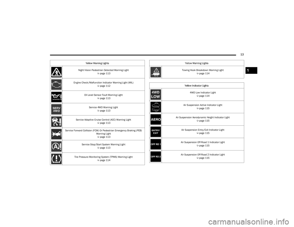
Night Vision Pedestrian Detected Warning Light Úpage 113
Engine Check/Malfunction Indicator Warning Light (MIL)
Úpage 112
Oil Level Sensor Fault Warning Light
Úpage 113
Service 4WD Warning Light
Úpage 113
Service Adaptive Cruise Control (ACC) Warning Light
Úpage 113
Service Forward Collision (FCW) Or Pedestrian Emergency Braking (PEB) Warning Light
Úpage 113
Service Stop/Start System Warning Light
Úpage 113
Tire Pressure Monitoring System (TPMS) Warning Light
Úpage 114
Yellow Warning Lights
Towing Hook Breakdown Warning Light
Úpage 114
Yellow Indicator Lights 4WD Low Indicator Light
Úpage 114
Air Suspension Active Indicator Light
Úpage 115
Air Suspension Aerodynamic Height Indicator Light
Úpage 115
Air Suspension Entry/Exit Indicator Light
Úpage 115
Air Suspension Off-Road 1 Indicator Light
Úpage 115
Air Suspension Off-Road 2 Indicator Light
Úpage 115
Yellow Warning Lights
1
23_WS_OM_EN_USC_t.book Page 13
Page 27 of 396

GETTING TO KNOW YOUR VEHICLE25
The Vehicle Security system is designed to protect your
vehicle. However, you can create conditions where the
system will give you a false alarm. If one of the previously
described arming sequences has occurred, the Vehicle
Security system will arm regardless of whether you are in
the vehicle or not. If you remain in the vehicle and open a
door, the alarm will sound. If this occurs, disarm the
Vehicle Security system.
If the Vehicle Security system is armed and the battery
becomes disconnected, the Vehicle Security system will
remain armed when the battery is reconnected; the
exterior lights will flash, and the horn will sound. If this
occurs, disarm the Vehicle Security system.
REARMING OF THE SYSTEM
If something triggers the alarm and no action is taken to
disarm it, the Vehicle Security system will turn the horn off
after a 29 second cycle (with five seconds between cycles
and up to eight cycles if the trigger remains active) and
then rearm itself.
SECURITY SYSTEM MANUAL OVERRIDE
The Vehicle Security system will not arm if you lock the
doors using the manual door lock, or an emergency lock
lever
Úpage 26.
TAMPER ALERT
If something has triggered the Vehicle Security system in
your absence, the horn will sound three times and the
exterior lights will blink three times when you disarm the
Vehicle Security system.
DELUXE VEHICLE SECURITY SYSTEM —
IF EQUIPPED
The Deluxe Vehicle Security system monitors the doors,
hood latch, and liftgate for unauthorized entry and the
ignition switch for unauthorized operation. The system
also includes a dual function intrusion sensor and vehicle
tilt sensor. The intrusion sensor monitors the vehicle
interior for motion. The vehicle tilt sensor monitors the
vehicle for any tilting actions (tow away, tire removal, ferry
transport, etc.).
If a perimeter violation triggers the security system, the
horn will sound for 29 seconds and the exterior lights will
flash followed by approximately five seconds of no activity.
This will continue for eight cycles if no action is taken to
disarm the system.
TO ARM THE SYSTEM
Follow these steps to arm the security system:
1. If any doors, windows, or the sunroof (if equipped)
are open, close them.
2. Make sure the vehicle ignition system is OFF.
3. Perform one of the following methods to lock the vehicle:
Push lock on the interior power door lock switch
with the driver and/or passenger door open.
Touch the lock button on the exterior Passive Entry
door handle with a key fob available in the same
exterior zone
Úpage 167.
Push the lock button on the key fob.
NOTE:
When armed, the interior motion sensor detects move -
ment within the vehicle's interior, including moving
objects (i.e. people and pets) and air currents through
open windows or the sunroof. The windows and
sunroof should be closed, and moving objects should
not be left in the vehicle when the intrusion detection
is armed, otherwise false alarms can occur.
Once the security system is armed, it remains in that
state until you disarm it by following either of the
disarming procedures described. If a power loss occurs
after arming the system, you must disarm the system
after restoring power to prevent alarm activation.
The ultrasonic intrusion sensor (motion detector)
actively monitors your vehicle every time you arm the
Vehicle Security system. If you prefer, you can turn off
the ultrasonic intrusion sensor when arming the
Vehicle Security system. To do so, push the lock button
on the key fob three times within 15 seconds of arming
the system (while the Vehicle Security Light is flashing
rapidly). The vehicle will remain locked but will disable
the alarm in the case of repeated false alarms due to
ambient conditions.
TO DISARM THE SYSTEM
The Vehicle Security system can be disarmed using any of
the following methods:
Push the unlock button on the key fob.
Grab the Passive Entry door handle to unlock the door
Úpage 167.
Cycle the vehicle ignition system out of the OFF position
by pushing the START/STOP ignition button (requires at
least one valid key fob in the vehicle).
2
23_WS_OM_EN_USC_t.book Page 25
Page 28 of 396
26GETTING TO KNOW YOUR VEHICLE
NOTE:
The driver's door key cylinder and the liftgate button on
the key fob cannot arm or disarm the Vehicle Security
system.
The Vehicle Security system remains armed during
power liftgate entry. If a valid key fob or the Passive
Entry liftgate button is used to open the liftgate, the
motion sensing will be suppressed until after the lift -
gate is closed. If someone enters the vehicle through
the opened liftgate, then opens any door, the alarm will
sound.
When the Vehicle Security system is armed, the interior
power door lock switches will not unlock the doors.
The ultrasonic intrusion sensor (motion detector)
actively monitors your vehicle every time you arm the
Vehicle Security system. If you prefer, you can turn off
the ultrasonic intrusion sensor when arming the
Vehicle Security system. To do so, push the lock button
on the key fob three times within 15 seconds of arming
the system (while the Vehicle Security Light is flashing
rapidly). The vehicle will remain locked but will disable
the alarm in the case of repeated false alarms due to
ambient conditions. The Vehicle Security system is designed to protect your
vehicle; however, you can create conditions where the
system will give you a false alarm. If one of the previously
described arming sequences has occurred, the Vehicle
Security system will arm regardless of whether you are in
the vehicle or not. If you remain in the vehicle and open a
door, the alarm will sound. If this occurs, disarm the
Vehicle Security system.
If the Vehicle Security system is armed and the battery
becomes disconnected, the Vehicle Security system will
remain armed when the battery is reconnected; the
exterior lights will flash and the horn will sound. If this
occurs, disarm the Vehicle Security system.
SECURITY SYSTEM MANUAL OVERRIDE
The Vehicle Security system will not arm if you lock the
doors using the manual door lock, or an emergency lock
lever
Úpage 26.
DOORS
MANUAL DOOR LOCKS
The front doors can be manually unlocked with a single
pull of the inside door handle. The driver’s door can also
be manually locked/unlocked by inserting the emergency
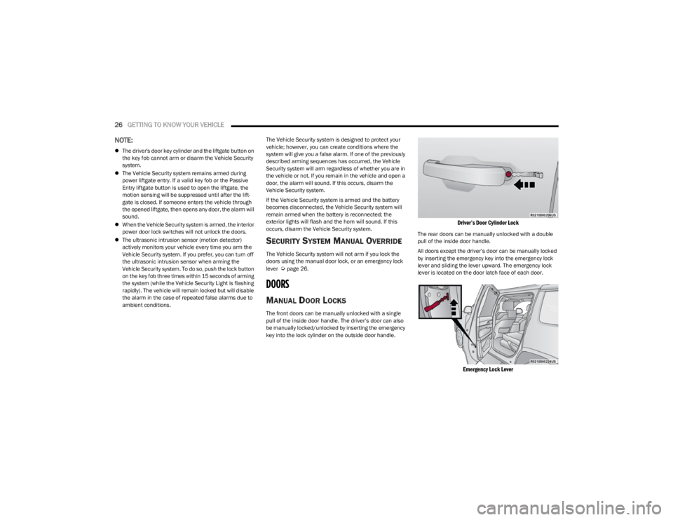
key into the lock cylinder on the outside door handle.
Driver’s Door Cylinder Lock
The rear doors can be manually unlocked with a double
pull of the inside door handle.
All doors except the driver’s door can be manually locked
by inserting the emergency key into the emergency lock
lever and sliding the lever upward. The emergency lock
lever is located on the door latch face of each door.
Emergency Lock Lever
23_WS_OM_EN_USC_t.book Page 26
Page 65 of 396
GETTING TO KNOW YOUR VEHICLE63
NOTE:If the vehicle is moving less than 10 mph (16 km/h), delay
times will be doubled.
Windshield Washer Operation
To use the washer, pull the lever rearward toward you and
hold. If the lever is pulled while on the intermittent setting,
the wipers will turn on and operate for several wipe cycles
after the lever is released, and then resume the
intermittent interval previously selected. If the lever is
pulled while the wipers are in the off position, the wipers
will operate several cycles, then turn off.
NOTE:
As a protective measure, the pump will stop if the
switch is held for more than 20 seconds. Once the
switch is released the pump will resume normal
operation.
If the front window washer feature is activated, all of
the front cameras (if equipped) on the vehicle will be
washed as well.
Mist
Use the Mist feature when weather conditions make
occasional usage of the wipers necessary. Push the lever
upward to the MIST position and release for a single
wiping cycle.
NOTE:The Mist feature does not activate the washer pump;
therefore, no washer fluid will be sprayed on the wind -
shield. The washer function must be used in order to spray
the windshield with washer fluid.
For information on wiper care and replacement, see
Úpage 324.
RAIN SENSING WIPERS — IF EQUIPPED
This feature senses rain or snowfall on the windshield and
automatically activates the wipers. Rotate the end of the
windshield wiper lever to one of the four detent positions
to activate this feature.
The sensitivity of the system is adjustable from the
windshield wiper lever. Wiper sensitivity position 1 is the
least sensitive, and wiper sensitivity position 4 is the most
sensitive.
NOTE:
The Rain Sensing feature will not operate when the
wiper switch is in the low or high position.
The Rain Sensing feature may not function properly
when ice or dried saltwater is present on the wind -
shield.
Use of products containing wax or silicone may reduce
rain sensor performance.
The Rain Sensing feature can be turned on and off
through the Uconnect system
Úpage 197.
The Rain Sensing system has protective features for the
wiper blades and arms. It will not operate under the
following conditions:
Low Temperature Wipe Inhibit — The Rain Sensing
feature will not operate when the ignition is first placed
in the ON position, when the vehicle is stationary and
the outside temperature is below 32°F (0°C), unless
the wiper control on the windshield wiper lever is
moved, the vehicle speed becomes greater than 3 mph
(5 km/h) or the outside temperature rises above
freezing.
Neutral Wipe Inhibit — The Rain Sensing feature will not
operate when the ignition is ON, when the transmission
gear selector is in the NEUTRAL position and the
vehicle speed is less than 3 mph (5 km/h), unless the
wiper control on the windshield wiper lever is moved,
the vehicle speed is greater than 3 mph (5 km/h) or
the gear selector is moved out of the NEUTRAL posi -
tion.
Remote Start Mode Inhibit — On vehicles equipped with
the Remote Start system, Rain Sensing wipers are not
operational when the vehicle is in the Remote Start
mode. Once the operator is in the vehicle and has
placed the ignition switch in the ON/RUN position, rain
sensing wiper operation can resume, if it has been
selected, and no other inhibit conditions
(mentioned previously) exist.
WARNING!
Sudden loss of visibility through the windshield could
lead to a collision. You might not see other vehicles or
other obstacles. To avoid sudden icing of the windshield
during freezing weather, warm the windshield with the
defroster before and during windshield washer use.
2
23_WS_OM_EN_USC_t.book Page 63
Page 89 of 396
GETTING TO KNOW YOUR VEHICLE87
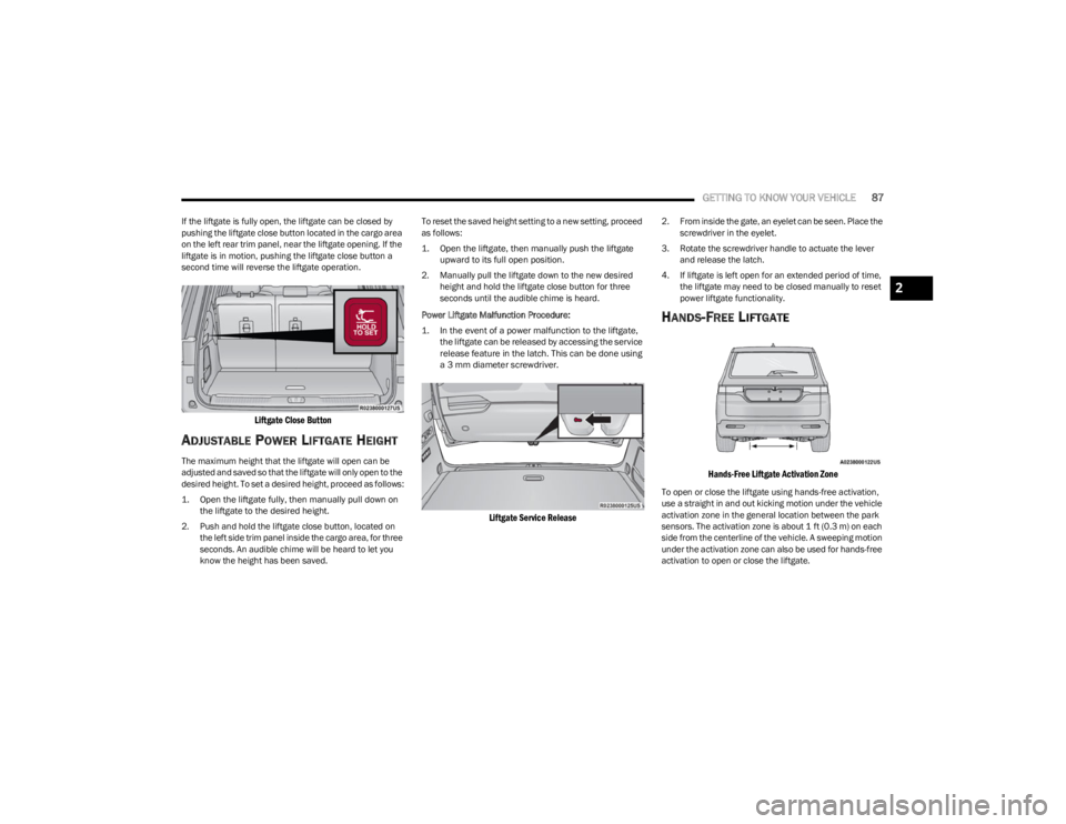
If the liftgate is fully open, the liftgate can be closed by
pushing the liftgate close button located in the cargo area
on the left rear trim panel, near the liftgate opening. If the
liftgate is in motion, pushing the liftgate close button a
second time will reverse the liftgate operation.
Liftgate Close Button
ADJUSTABLE POWER LIFTGATE HEIGHT
The maximum height that the liftgate will open can be
adjusted and saved so that the liftgate will only open to the
desired height. To set a desired height, proceed as follows:
1. Open the liftgate fully, then manually pull down on
the liftgate to the desired height.
2. Push and hold the liftgate close button, located on the left side trim panel inside the cargo area, for three
seconds. An audible chime will be heard to let you
know the height has been saved. To reset the saved height setting to a new setting, proceed
as follows:
1. Open the liftgate, then manually push the liftgate
upward to its full open position.
2. Manually pull the liftgate down to the new desired height and hold the liftgate close button for three
seconds until the audible chime is heard.
Power Liftgate Malfunction Procedure:
1. In the event of a power malfunction to the liftgate, the liftgate can be released by accessing the service
release feature in the latch. This can be done using
a 3 mm diameter screwdriver.
Liftgate Service Release
2. From inside the gate, an eyelet can be seen. Place the screwdriver in the eyelet.
3. Rotate the screwdriver handle to actuate the lever and release the latch.
4. If liftgate is left open for an extended period of time, the liftgate may need to be closed manually to reset
power liftgate functionality.
HANDS-FREE LIFTGATE
Hands-Free Liftgate Activation Zone
To open or close the liftgate using hands-free activation,
use a straight in and out kicking motion under the vehicle
activation zone in the general location between the park
sensors. The activation zone is about 1 ft (0.3 m) on each
side from the centerline of the vehicle. A sweeping motion
under the activation zone can also be used for hands-free
activation to open or close the liftgate.
2
23_WS_OM_EN_USC_t.book Page 87
Page 90 of 396
88GETTING TO KNOW YOUR VEHICLE
NOTE:The activation zone is the same for vehicles equipped with
or without a trailer tow package.
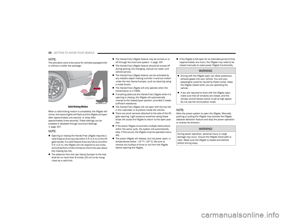
Valid Kicking Motion
When a valid kicking motion is completed, the liftgate will
chime, the hazard lights will flash and the liftgate will open
after approximately one second, or close after
approximately three seconds. These settings can be
enabled or disabled through Uconnect Settings
Úpage 197.
NOTE:
Opening or closing the Hands-Free Liftgate requires a
valid Passive Entry key fob within 5 ft (1.5 m) of the lift -
gate handle. If a valid Passive Entry key fob is not within
5 ft (1.5 m), the liftgate will not respond to any kicks,
and will perform inhibit chimes to inform the user about
the missing key fob.
The distance from the rear fascia/bumper to the foot
shall be no more than 8 inches (20 cm) to be recog -
nized as a valid kick.
The Hands-Free Liftgate feature may be turned on or
off through the Uconnect system
Úpage 197.
The Hands-Free Liftgate feature should be turned off
during jacking, tire changing, manual car wash, and
vehicle service.
The Hands-Free Liftgate feature can be activated by
any metallic object making a similar in-and-out motion
under the rear fascia/bumper, such as cleaning using
a metal broom.
The Hands-Free Liftgate will only operate when the
transmission is in PARK.
If anything obstructs the Hands-Free Liftgate while it is
opening or closing, the liftgate will automatically
reverse to the closed/open position, provided it meets
sufficient resistance.
The Hands-Free Liftgate will not open with the key fob
in the cupholder or anywhere inside the vehicle.
There are pinch sensors attached to the side of the lift -
gate opening. Light pressure anywhere along these
strips will cause the liftgate to return to the open posi -
tion.
If the power liftgate encounters multiple obstructions
within the same cycle, the system will automatically
stop. If this occurs, the liftgate must be operated manu -
ally.
The power liftgate will release, but not power open, in
temperatures below −12°F (−24°C). Be sure to
remove any buildup of snow or ice from the liftgate
before opening the liftgate.
If the liftgate is left open for an extended period of time
(approximately one hour), the liftgate may need to be
closed manually to reset power liftgate functionality.
NOTE:Allow the power system to open the liftgate. Manually
pushing or pulling the liftgate may activate the liftgate
obstacle detection feature and stop the power operation
or reverse its direction.
WARNING!
Driving with the liftgate open can allow poisonous
exhaust gases into your vehicle. You and your
passengers could be injured by these fumes. Keep
the liftgate closed when you are operating the
vehicle.
If you are required to drive with the liftgate open,
make sure that all windows are closed, and the
climate control blower switch is set at high speed.
Do not use the recirculation mode.
WARNING!
During power operation, personal injury or cargo
damage may occur. Ensure the liftgate travel path is
clear. Make sure the liftgate is closed and latched
before driving away.
23_WS_OM_EN_USC_t.book Page 88
Page 109 of 396
GETTING TO KNOW YOUR INSTRUMENT PANEL107
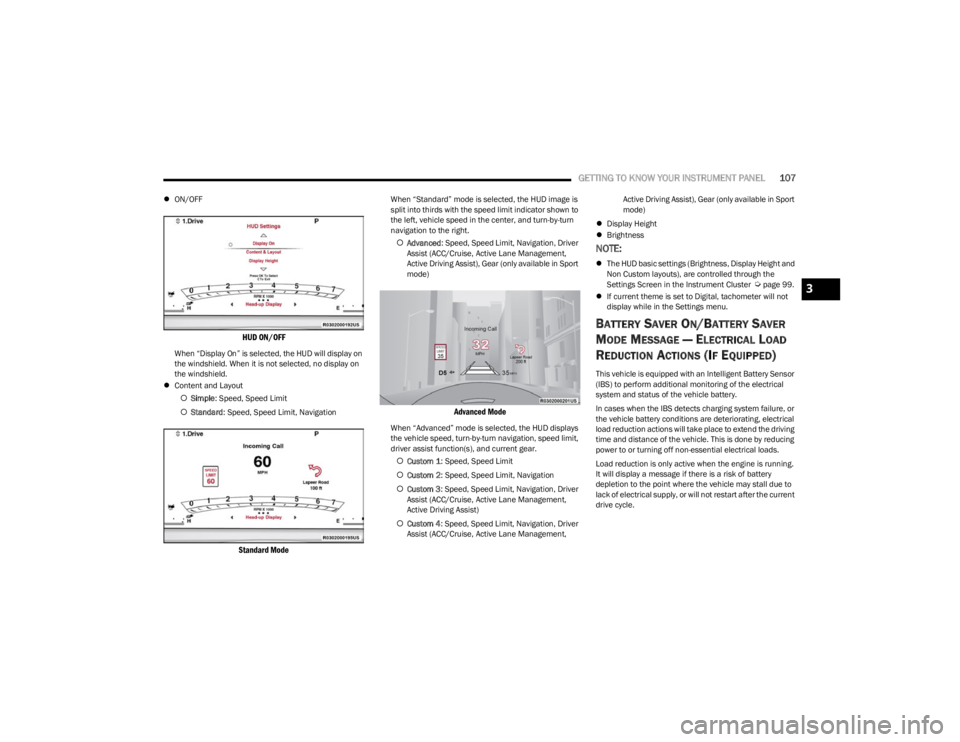
ON/OFF
HUD ON/OFF
When “Display On” is selected, the HUD will display on
the windshield. When it is not selected, no display on
the windshield.
Content and Layout
Simple : Speed, Speed Limit
Standard : Speed, Speed Limit, Navigation
Standard Mode
When “Standard” mode is selected, the HUD image is
split into thirds with the speed limit indicator shown to
the left, vehicle speed in the center, and turn-by-turn
navigation to the right.
Advanced : Speed, Speed Limit, Navigation, Driver
Assist (ACC/Cruise, Active Lane Management,
Active Driving Assist), Gear (only available in Sport
mode)
Advanced Mode
When “Advanced” mode is selected, the HUD displays
the vehicle speed, turn-by-turn navigation, speed limit,
driver assist function(s), and current gear.
Custom 1 : Speed, Speed Limit
Custom 2 : Speed, Speed Limit, Navigation
Custom 3 : Speed, Speed Limit, Navigation, Driver
Assist (ACC/Cruise, Active Lane Management,
Active Driving Assist)
Custom 4 : Speed, Speed Limit, Navigation, Driver
Assist (ACC/Cruise, Active Lane Management, Active Driving Assist), Gear (only available in Sport
mode)
Display Height
Brightness
NOTE:
The HUD basic settings (Brightness, Display Height and
Non Custom layouts), are controlled through the
Settings Screen in the Instrument Cluster
Úpage 99.
If current theme is set to Digital, tachometer will not
display while in the Settings menu.
BATTERY SAVER ON/BATTERY SAVER
M
ODE MESSAGE — ELECTRICAL LOAD
R
EDUCTION ACTIONS (IF EQUIPPED)
This vehicle is equipped with an Intelligent Battery Sensor
(IBS) to perform additional monitoring of the electrical
system and status of the vehicle battery.
In cases when the IBS detects charging system failure, or
the vehicle battery conditions are deteriorating, electrical
load reduction actions will take place to extend the driving
time and distance of the vehicle. This is done by reducing
power to or turning off non-essential electrical loads.
Load reduction is only active when the engine is running.
It will display a message if there is a risk of battery
depletion to the point where the vehicle may stall due to
lack of electrical supply, or will not restart after the current
drive cycle.
3
23_WS_OM_EN_USC_t.book Page 107
Page 115 of 396
GETTING TO KNOW YOUR INSTRUMENT PANEL113
When the engine is running, the MIL may flash to alert
serious conditions that could lead to immediate loss of
power or severe catalytic converter damage. The vehicle
should be serviced by an authorized dealer as soon as
possible if this occurs.Night Vision Animal Detected Warning
Light — If Equipped
This light alerts the driver that the Night Vision
Warning System has detected an animal
approaching in the vehicle’s path.
Night Vision Pedestrian Detected
Warning Light — If Equipped
This indicator light alerts the driver that the
Night Vision System has detected a pedestrian
approaching in the vehicle’s path.
Oil Level Sensor Fault Warning Light —
If Equipped
This warning light will illuminate to indicate a
fault with the engine oil level sensor. Contact
an authorized dealer for service.
Service 4WD Warning Light — If Equipped
This warning light will illuminate to signal a fault
with the 4WD system. If the light stays on or
comes on during driving, it means that the 4WD
system is not functioning properly and that
service is required. We recommend you drive to the
nearest service center and have the vehicle serviced
immediately.
Service Adaptive Cruise Control (ACC)
Warning Light
This light will turn on when the ACC is not
operating and needs service Úpage 139.
Service Forward Collision Warning (FCW)
Or Pedestrian Emergency Braking (PEB)
Warning Light
This warning light will illuminate to indicate a
fault in the FCW or PEB System. Contact an
authorized dealer for service
Úpage 250.
Service Stop/Start System Warning Light
This warning light will illuminate when the
Stop/Start system is not functioning properly
and service is required. Contact an authorized
dealer for service.
WARNING!
A malfunctioning catalytic converter, as referenced
previously, can reach higher temperatures than in
normal operating conditions. This can cause a fire if you
drive slowly or park over flammable substances such as
dry plants, wood, cardboard, etc. This could result in
death or serious injury to the driver, occupants or
others.
CAUTION!
Prolonged driving with the Malfunction Indicator Light
(MIL) on could cause damage to the vehicle control
system. It also could affect fuel economy and
driveability. If the MIL is flashing, severe catalytic
converter damage and power loss will soon occur.
Immediate service is required.
3
23_WS_OM_EN_USC_t.book Page 113
Page 116 of 396
114GETTING TO KNOW YOUR INSTRUMENT PANEL
Tire Pressure Monitoring System (TPMS)
Warning Light
The warning light switches on and a message is
displayed to indicate that the tire pressure is
lower than the recommended value and/or
that slow pressure loss is occurring. In these
cases, optimal tire duration and fuel consumption may not
be guaranteed.
Should one or more tires be in the condition mentioned
previously, the display will show the indications
corresponding to each tire.
Each tire, including the spare (if provided), should be
checked monthly when cold and inflated to the inflation
pressure recommended by the vehicle manufacturer on
the vehicle placard or tire inflation pressure label. If your
vehicle has tires of a different size than the size indicated
on the vehicle placard or tire inflation pressure label, you
should determine the proper tire inflation pressure for
those tires. As an added safety feature, your vehicle has been
equipped with a TPMS that illuminates a low tire pressure
telltale when one or more of your tires is significantly
underinflated. Accordingly, when the low tire pressure
telltale illuminates, you should stop and check your tires
as soon as possible, and inflate them to the proper
pressure. Driving on a significantly underinflated tire
causes the tire to overheat and can lead to tire failure.
Underinflation also reduces fuel efficiency and tire tread
life, and may affect the vehicle’s handling and stopping
ability.
Please note that the TPMS is not a substitute for proper
tire maintenance, and it is the driver’s responsibility to
maintain correct tire pressure, even if underinflation has
not reached the level to trigger illumination of the TPMS
low tire pressure telltale.
Your vehicle has also been equipped with a TPMS
malfunction indicator to indicate when the system is not
operating properly. The TPMS malfunction indicator is
combined with the low tire pressure telltale. When the
system detects a malfunction, the telltale will flash for
approximately one minute and then remain continuously
illuminated. This sequence will continue upon subsequent
vehicle start-ups as long as the malfunction exists. When
the malfunction indicator is illuminated, the system may
not be able to detect or signal low tire pressure as
intended. TPMS malfunctions may occur for a variety of
reasons, including the installation of replacement or
alternate tires or wheels on the vehicle that prevent the
TPMS from functioning properly. Always check the TPMS
malfunction telltale after replacing one or more tires or
wheels on your vehicle to ensure that the replacement or
alternate tires and wheels allow the TPMS to continue to
function properly
Úpage 252.
Towing Hook Breakdown Warning Light —
If Equipped
This light illuminates when there is a failure
with the tow hook. Contact an authorized
dealer for service.
YELLOW INDICATOR LIGHTS
4WD Low Indicator Light — If Equipped
This light alerts the driver that the vehicle is in
the 4WD Low mode. The front and rear
driveshafts are mechanically locked together
forcing the front and rear wheels to rotate at
the same speed. Low range provides a greater gear
reduction ratio to provide increased torque at the wheels
Úpage 129.
CAUTION!
Do not continue driving with one or more flat tires as
handling may be compromised. Stop the vehicle,
avoiding sharp braking and steering. If a tire puncture
occurs, repair immediately using the dedicated tire
repair kit and contact an authorized dealer as soon as
possible.
CAUTION!
The TPMS has been optimized for the original
equipment tires and wheels. TPMS pressures and
warning have been established for the tire size
equipped on your vehicle. Undesirable system
operation or sensor damage may result when using
replacement equipment that is not of the same size,
type, and/or style. Aftermarket wheels can cause
sensor damage. Using aftermarket tire sealants may
cause the Tire Pressure Monitoring System (TPMS)
sensor to become inoperable. After using an
aftermarket tire sealant it is recommended that you
take your vehicle to an authorized dealer to have your
sensor function checked.
23_WS_OM_EN_USC_t.book Page 114