instrument cluster JEEP WRANGLER 2009 Owners Manual
[x] Cancel search | Manufacturer: JEEP, Model Year: 2009, Model line: WRANGLER, Model: JEEP WRANGLER 2009Pages: 502, PDF Size: 13.82 MB
Page 20 of 502
Rearming The System
If something triggers the alarm, and no action is taken to
disarm it, the Vehicle Security Alarm will turn off the
horn after three minutes, turn off all of the visual signals
after 15 minutes, and then the Vehicle Security Alarm will
rearm itself.
To Set the Alarm
The Vehicle Security Alarm will set when you use the
Remote Keyless Entry (RKE) transmitter to lock the doors
and swing gate, or when you use the power door lock
switch while the door is open. After all the doors are
locked and closed, the Vehicle Security Light (located on
the instrument cluster) will flash rapidly for about 16 sec-
onds to signal that the Vehicle Security Alarm is arming.
During this 16 second arming period, opening any door
or the swing gate will cancel the arming. If the Vehicle
Security Alarm successfully arms, the Vehicle Security
Light will flash at a slower rate to indicate the Vehicle
Security Alarm is set.
To Disarm the System
To disarm the Vehicle Security Alarm, you will need to
press the UNLOCK button on the RKE transmitter, or
turn the ignition key to the ON position. If something has
triggered the Vehicle Security Alarm in your absence, the
horn will sound three times when you unlock the doors.
Check the vehicle for tampering.
The Vehicle Security Alarm is designed to protect your
vehicle; however, you can create conditions where the
Vehicle Security Alarm will arm unexpectedly. If you
remain in the vehicle and lock the doors with the RKE
transmitter, once the Vehicle Security Alarm is armed
(after 16 seconds), when you pull the door handle to exit,
the alarm will sound. If this occurs, press the UNLOCK
button on the RKE transmitter to disarm the Vehicle
Security Alarm. You may also accidentally disarm the
Vehicle Security Alarm by unlocking the driver’s door
with the key and then locking it. The door will be locked
but the Vehicle Security Alarm will not arm.
18 THINGS TO KNOW BEFORE STARTING YOUR VEHICLE
Page 98 of 502
Headlight Dimmer Switch
Push the multifunction lever away from you to switch
the headlights to high beam. Pull the lever toward you to
switch the headlights back to low beam.
Flash-To-Pass
You can signal another vehicle with your headlights by
lightly pulling the multifunction lever toward the steer-
ing wheel. This will turn on the high beam headlights
until the lever is released.
Front Fog Lights — If Equipped
The front fog light switch is located on the multi-
function lever. To activate the front fog lights, turn
on the parking or low beam headlights and pull
out the end of the lever.
NOTE: The fog lights will only operate with the parking
lights or the headlights on low beam. Selecting high
beam headlights will turn off the fog lights.
Turn Signals
Move the multifunction lever up or down, and the
arrows on each side of the instrument cluster flash, to
show proper operation of the front and rear turn signal
lights.
If either light has a very fast flash rate, check for a
defective outside light bulb. If an indicator fails to light
when the lever is moved, it would suggest that the fuse
or indicator is defective or there may be a circuit failure.
NOTE: A tone will chime if the turn signals are left on
for more than 1 mile (2 km).
Lane Change Assist
Tap the lever up or down once without moving beyond
the detent and the turn signal (right or left) will flash
three times the automatically turn off.
Page 202 of 502
INSTRUMENT CLUSTER DESCRIPTION
1. Fuel Gauge
The pointer shows the level of fuel in the fuel tank.
NOTE:When the ignition switch is turned to OFF, the
fuel gauge, voltmeter, oil pressure and temperature
gauges may not show accurate readings. When the
engine is not running, turn the ignition switch to ON to
obtain accurate readings.
2. Charging System Light This light shows the status of the electrical charg-
ing system. The light should come on when the
ignition switch is first turned ON, and remain on briefly
as a bulb check. If the light stays on or comes on while
driving, turn off some of the vehicle’s non-essential
electrical devices or increase engine speed (if at idle). If
the charging system light remains on, it means that the vehicle is experiencing a problem with the charging
system. Obtain SERVICE IMMEDIATELY. See an autho-
rized dealer.
If jump starting is required, refer to “Jump Starting
Procedures” in section 6 of this manual.
3. Front Fog Light Indicator — If Equipped
This indicator will illuminate when the front fog
lights are on.
4. Low Fuel Warning Light When the fuel level reaches approximately 2.8 gal
(10.6L) this light will turn on and a single chime
will sound.
5. Speedometer
Indicates vehicle speed.
Page 208 of 502
21. Odometer / Trip Odometer Reset Button
Press this button to change the display from odometer to
either of the two trip odometer settings. Trip A or Trip B
will appear when in the trip odometer mode. Press and
hold the button for two seconds to reset the trip odometer
to 0 miles or kilometers. The odometer must be in trip
mode to reset.
22. Shift Lever Indicator
The Shift Lever Indicator is self-contained within the
instrument cluster. It displays the gear position of the
automatic transmission.
23. Tire Pressure Monitoring Telltale LightEach tire, including the spare (if provided),
should be checked monthly, when cold and
inflated to the inflation pressure recommended
by the vehicle manufacturer on the vehicle placard or tire
inflation pressure label. (If your vehicle has tires of a
different size than the size indicated on the vehicle placard or tire inflation pressure label, you should deter-
mine the proper tire inflation pressure for those tires.)
As an added safety feature, your vehicle has been
equipped with a Tire Pressure Monitoring System
(TPMS) that illuminates a low tire pressure telltale when
one or more of your tires is significantly under-inflated.
Accordingly, when the low tire pressure telltale illumi-
nates, you should stop and check your tires as soon as
possible, and inflate them to the proper pressure. Driving
on a significantly under-inflated tire causes the tire to
overheat and can lead to tire failure. Under-inflation also
reduces fuel efficiency and tire tread life, and may affect
the vehicle’s handling and stopping ability.
Please note that the TPMS is not a substitute for proper
tire maintenance, and it is the driver ’s responsibility to
maintain correct tire pressure, even if under-inflation has
not reached the level to trigger illumination of the TPMS
low tire pressure telltale.
Page 216 of 502
Reset / Change Display
Press and hold the left button (on the instrument cluster)
while function is being displayed to reset or change the
display.
The following trip displays can be reset or changed:
•AVG ECO (changes to present fuel economy)
•ET (will reset display)
Trip Conditions
Average Fuel Economy (AVG ECO)
This display shows the average fuel economy.
Estimated Range (DTE)
This display shows the estimated distance that can be
traveled with the fuel remaining in the tank. This esti-
mated distance is based on the most recent trip informa-
tion: (Average Fuel Economy) x (Fuel Remaining).
This display cannot be reset.
Elapsed Time (ET)
This display shows the accumulated ignition ON time
since the last reset.
Trip Odometer (ODO)
This display shows the distance traveled since the last
reset. Press and release the right button (on the instru-
ment cluster) to switch from odometer, to Trip A or Trip
B. Press and hold the right button while the odometer/
trip odometer is displayed to reset.
Trip A
Shows the total distance traveled for Trip A since the last
reset.
Trip B
Shows the total distance traveled for Trip B since the last
reset.
214 UNDERSTANDING YOUR INSTRUMENT PANEL
Page 218 of 502
Automatic Compass Calibration
The self-calibrating feature of the compass eliminates the
need to calibrate the compass for normal conditions.
During a short initial period, the compass may appear
erratic and the CAL symbol will appear (blinking) on the
display. After the vehicle has completed at least one
complete circle under 5 mph (8 km/h) in an area free
from large metal objects, calibration will be complete
when the CAL symbol is extinguished.
After initial calibration, the compass will continue to
automatically update this calibration whenever the ve-
hicle is in motion.
Manual Compass Calibration
NOTE: Before attempting a manual compass calibra-
tion, the engine must be running and the transmission
in the PARK position (if equipped).If the compass appears erratic or inaccurate and the
variance has been properly set, you may wish to manu-
ally recalibrate the compass. To manually calibrate the
compass:
1. First enter the variance mode. Press and hold the left
button (located on the instrument cluster) for approxi-
mately 10 seconds to enter the variance mode, and
release the button when the VAR (Compass Variance)
symbol appears.
2. The current variance value will also be displayed.
Once in the variance mode, it is necessary to release the
button, and then press and hold it again (approximately
10 seconds) until CAL is displayed (solid, not blinking).
216 UNDERSTANDING YOUR INSTRUMENT PANEL
Page 294 of 502
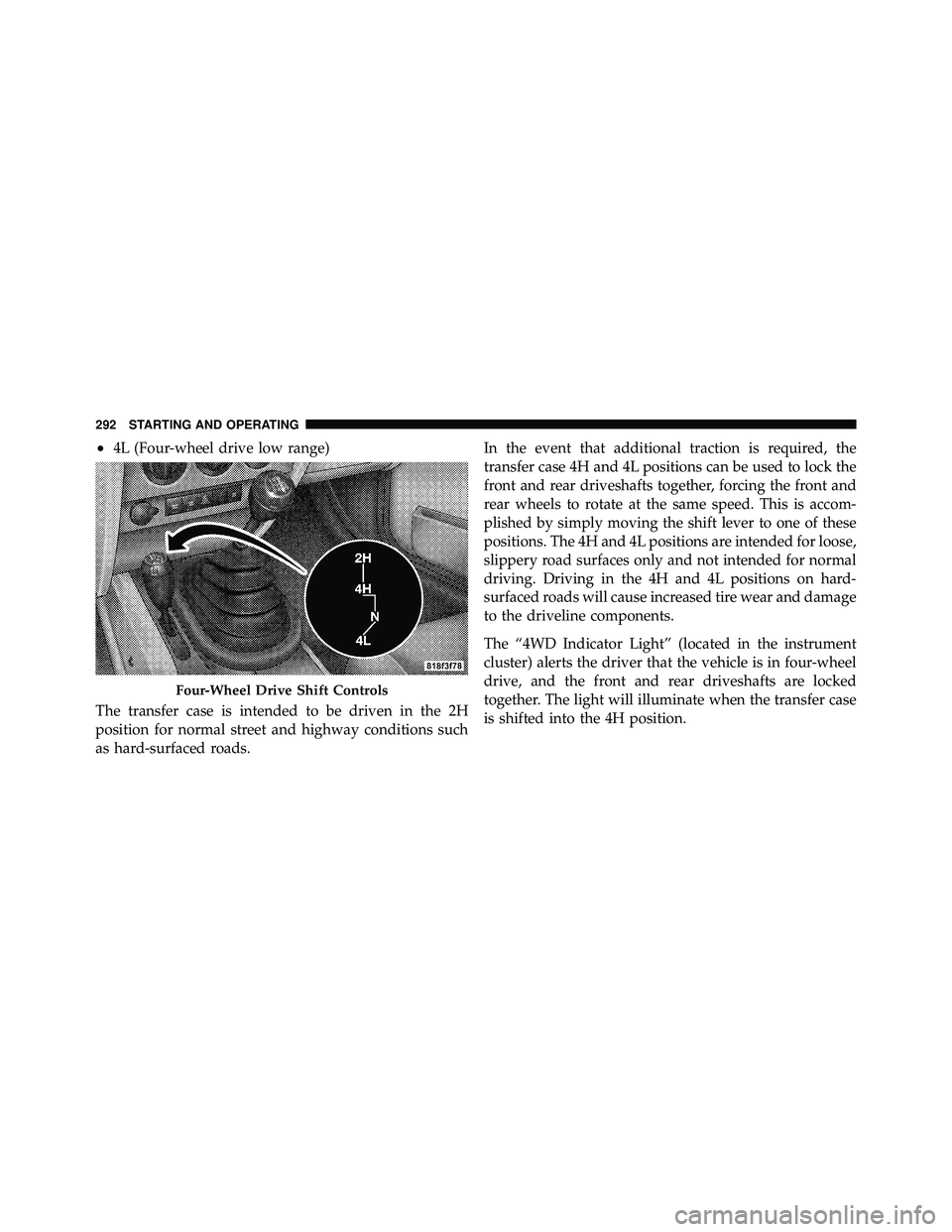
•4L (Four-wheel drive low range)
The transfer case is intended to be driven in the 2H
position for normal street and highway conditions such
as hard-surfaced roads. In the event that additional traction is required, the
transfer case 4H and 4L positions can be used to lock the
front and rear driveshafts together, forcing the front and
rear wheels to rotate at the same speed. This is accom-
plished by simply moving the shift lever to one of these
positions. The 4H and 4L positions are intended for loose,
slippery road surfaces only and not intended for normal
driving. Driving in the 4H and 4L positions on hard-
surfaced roads will cause increased tire wear and damage
to the driveline components.
The “4WD Indicator Light” (located in the instrument
cluster) alerts the driver that the vehicle is in four-wheel
drive, and the front and rear driveshafts are locked
together. The light will illuminate when the transfer case
is shifted into the 4H position.
Page 296 of 502
4H Position
This range locks the front and rear driveshafts together,
forcing the front and rear wheels to rotate at the same
speed. This range (4H) provides additional traction for
loose, slippery road surfaces and should not be used on
wet or dry pavement.
The “4WD Indicator Light” (located in the instrument
cluster) will illuminate when the transfer case is shifted
into the 4H position.
N (Neutral) Position
This range disengages the front and rear driveshafts from
the powertrain. It is to be used for flat towing behind
another vehicle. Refer to “Recreational Towing” in Sec-
tion 5 of this manual.
4L Position
This range locks the front and rear driveshafts together,
forcing the front and rear wheels to rotate at the samespeed. This range (4L) provides additional traction and
maximum pulling power for loose, slippery road surfaces
only. Do not exceed 25 mph (40 km/h).
The “4WD Indicator Light” (located in the instrument
cluster) will illuminate when the transfer case is shifted
into the 4L position.
Shifting Procedure
2H to 4H or 4H to 2H
Shifting between 2H and 4H can be made with the
vehicle stopped or in motion. If the vehicle is in motion,
shifts can be made up to 50 mph (80 km/h). With the
vehicle in motion, the transfer case will engage/
disengage faster if you momentarily release the accelera-
tor pedal after completing the shift. Apply a constant
force when shifting the transfer case lever.
294 STARTING AND OPERATING
Page 300 of 502
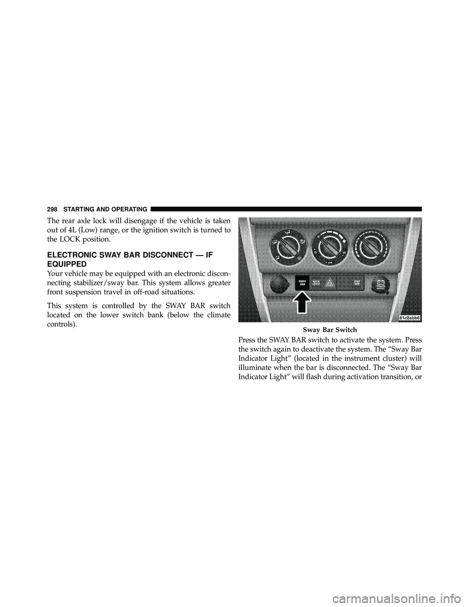
The rear axle lock will disengage if the vehicle is taken
out of 4L (Low) range, or the ignition switch is turned to
the LOCK position.
ELECTRONIC SWAY BAR DISCONNECT — IF
EQUIPPED
Your vehicle may be equipped with an electronic discon-
necting stabilizer/sway bar. This system allows greater
front suspension travel in off-road situations.
This system is controlled by the SWAY BAR switch
located on the lower switch bank (below the climate
controls).Press the SWAY BAR switch to activate the system. Press
the switch again to deactivate the system. The “Sway Bar
Indicator Light” (located in the instrument cluster) will
illuminate when the bar is disconnected. The “Sway Bar
Indicator Light” will flash during activation transition, or
Page 356 of 502
The Tire Pressure Monitor System (TPMS) consists of the
following components:
•Receiver Module
•Four Tire Pressure Monitoring Sensors
•Tire Pressure Monitoring Telltale Light
A tire pressure monitoring sensor is located in the spare
wheel if the vehicle is equipped with a matching full size
spare wheel and tire assembly. The matching full size
spare tire can be used in place of any of the four road
tires. A low spare tire will not cause the “Tire Pressure
Monitoring Telltale Light” to illuminate or the chime to
sound. The “Tire Pressure Monitoring Telltale Light” will
illuminate in the instrument cluster, and an au-
dible chime will be activated when one or more of
the four active road tire pressures are low. Should this
occur, you should stop as soon as possible, check the inflation pressure of each tire on your vehicle, and inflate
each tire to the vehicle’s recommended cold placard
pressure value. The system will automatically update
and the “Tire Pressure Monitoring Telltale Light” will
extinguish once the updated tire pressures have been
received. The vehicle may need to be driven for up to
20 minutes above 15 mph (25 km/h) to receive this
information.
The “Tire Pressure Monitoring Telltale Light” will flash
on and off for 75 seconds, and will remain on solid when
a system fault is detected. The system fault will also
sound a chime. If the ignition key is cycled, this sequence
will repeat, providing the system fault still exists. A
system fault can occur by any of the following scenarios:
1. Jamming due to electronic devices or driving next to
facilities emitting the same Radio Frequencies as the TPM
sensors.