turn signal JEEP WRANGLER 2011 JK / 3.G User Guide
[x] Cancel search | Manufacturer: JEEP, Model Year: 2011, Model line: WRANGLER, Model: JEEP WRANGLER 2011 JK / 3.GPages: 88, PDF Size: 3.52 MB
Page 3 of 88
INTRODUCTION/WELCOME
Welcome From Chrysler Group LLC....2
CONTROLS AT A GLANCE
Driver Cockpit................4
Instrument Cluster .............6
GETTING STARTED
KeyFOB ..................8
Remote Start................8
Theft Alarm .................9
Seat Belt ..................9
Supplemental Restraint System (SRS) —
Airbags .................. 10
Child Restraints .............. 11
Front Seats ................ 13
Rear Seats ................ 15
Tilt Steering Column ........... 16
Heated Seats ............... 16
OPERATING YOUR VEHICLETurn Signal/Lights Lever ......... 18
Wiper/Washer Lever ........... 19
Speed Control .............. 19
Manual Climate Controls ......... 21
Automatic Temperature Controls (ATC) . . 21
Soft Top And Sunrider
®.......... 23
Hard Top And Freedom Top®....... 27
Wind Buffeting .............. 29
ELECTRONICSYour Vehicle's Sound System ...... 30
Non-Touch-Screen Radios ........ 32
Touch-Screen Radio ........... 35
Steering Wheel Audio Controls ...... 41
Uconnect™ Phone ............ 41
Uconnect™ Voice Command ...... 43
iPod
®/USB/MP3 Control ......... 44
Electronic Vehicle Information Center
(EVIC) ................... 45
Programmable Features ......... 46
Power Inverter .............. 47
Power Outlets ............... 48
OFF-ROAD CAPABILITIESCommand-Trac®/Rock-Trac®...... 49 Axle Lock (Tru-Lok
®) Rubicon Only
.... 49
Electronic Sway Bar Disconnect –
Rubicon Only ............... 49
UTILITYTrailer Towing Weights (Maximum Trailer
Weight Ratings) .............. 50
Overdrive Off Switch ........... 52
Recreational Towing (Behind
Motorhome) ................ 52
WHAT TO DO IN EMERGENCIES24-Hour Towing Assistance ....... 54
Instrument Cluster Warning Lights .... 54
If Your Engine Overheats ......... 58
Jacking And Tire Changing ........ 59
Jump-Starting .............. 62
Emergency Tow Hooks .......... 64
Shift Lever Override ............ 64
Towing A Disabled Vehicle ........ 65
Freeing A Stuck Vehicle .......... 65
Event Data Recorder (EDR) ........ 66
MAINTAINING YOUR VEHICLEOpening The Hood............ 67
Engine Compartment ........... 68
Fluids And Capacities ........... 69
Maintenance Chart ............ 70
Fuses ................... 73
Tire Pressures ............... 76
Wheel And Wheel Trim Care ....... 77
Exterior Bulbs ............... 77
CONSUMER ASSISTANCEChrysler Group LLC Customer Center . . 78
Chrysler Canada Inc. Customer
Center................... 78
Assistance For The Hearing Impaired . . 78
Publications Ordering ........... 78
Reporting Safety Defects In The
50 United States And
Washington, D.C. ............. 79
MOPAR ACCESSORIESAuthentic Accessories By MOPAR®... 80
INDEX.................. 81
TABLE OF CONTENTS
Page 9 of 88
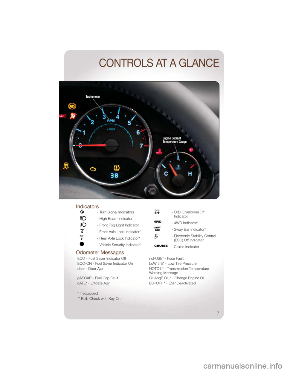
Indicators
- Turn Signal Indicators
- High Beam Indicator
- Front Fog Light Indicator
- Front Axle Lock Indicator*
- Rear Axle Lock Indicator*
- Vehicle Security Indicator*
- O/D (Overdrive) OffIndicator
- 4WD Indicator*
- Sway Bar Indicator*
- Electronic Stability Control(ESC) Off Indicator
- Cruise Indicator
Odometer Messages
ECO - Fuel Saver Indicator Off noFUSE* - Fuse Fault
ECO-ON - Fuel Saver Indicator On LoW tirE* - Low Tire Pressure
door - Door Ajar HOTOIL* - Transmission Temperature
Warning Message
gASCAP - Fuel Cap Fault CHAngE OIL* - Change Engine Oil
gATE* - Liftgate Ajar ESPOFF * - ESP Deactivated
* If equipped
** Bulb Check with Key On
CONTROLS AT A GLANCE
7
Page 18 of 88
TILT STEERING COLUMN
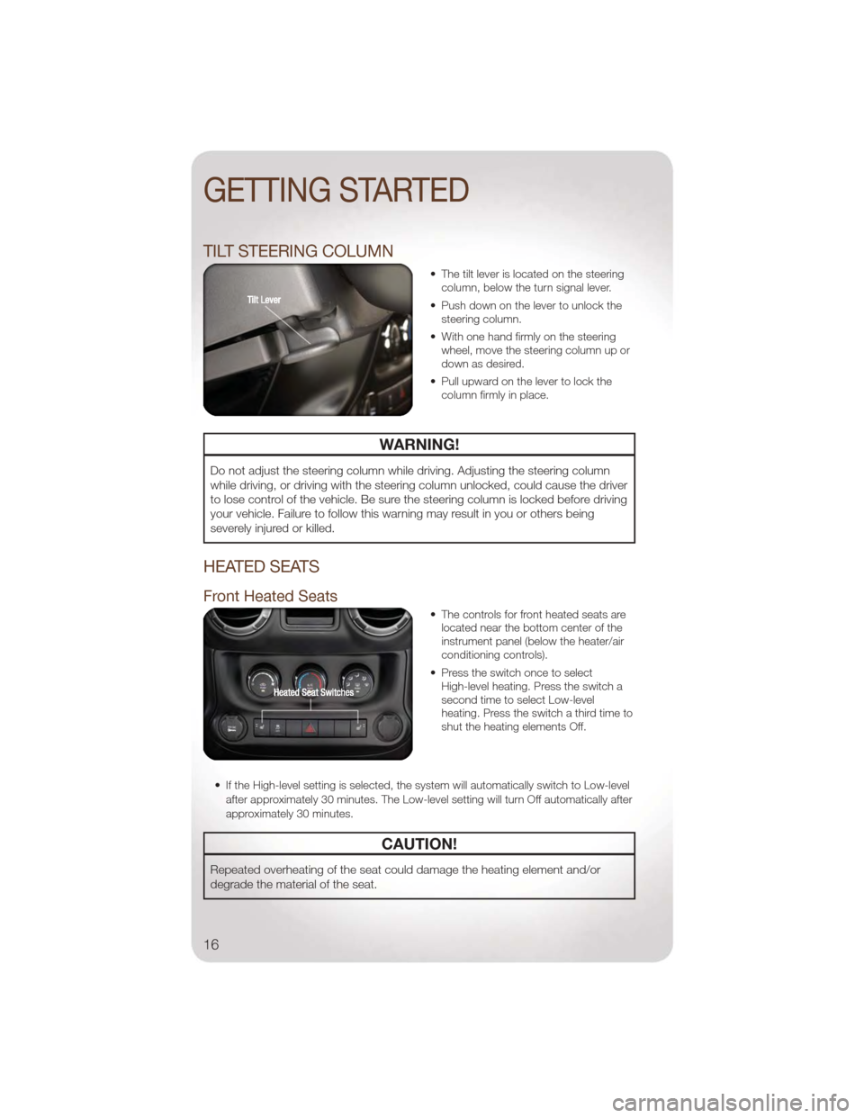
• The tilt lever is located on the steeringcolumn, below the turn signal lever.
• Push down on the lever to unlock the steering column.
• With one hand firmly on the steering wheel, move the steering column up or
down as desired.
• Pull upward on the lever to lock the column firmly in place.
WARNING!
Do not adjust the steering column while driving. Adjusting the steering column
while driving, or driving with the steering column unlocked, could cause the driver
to lose control of the vehicle. Be sure the steering column is locked before driving
your vehicle. Failure to follow this warning may result in you or others being
severely injured or killed.
HEATED SEATS
Front Heated Seats
• The controls for front heated seats arelocated near the bottom center of the
instrument panel (below the heater/air
conditioning controls).
• Press the switch once to select High-level heating. Press the switch a
second time to select Low-level
heating. Press the switch a third time to
shut the heating elements Off.
• If the High-level setting is selected, the system will automatically switch to Low-level after approximately 30 minutes. The Low-level setting will turn Off automatically after
approximately 30 minutes.
CAUTION!
Repeated overheating of the seat could damage the heating element and/or
degrade the material of the seat.
GETTING STARTED
16
Page 20 of 88
TURN SIGNAL/LIGHTS LEVER
Headlights/Parking Lights/Automatic Headlights
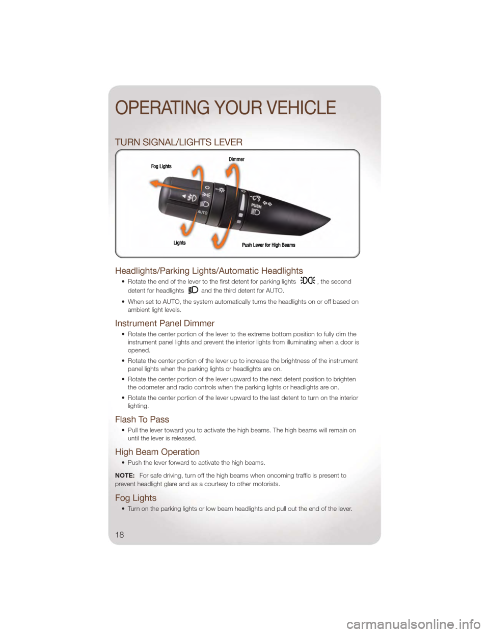
• Rotate the end of the lever to the first detent for parking lights, the second
detent for headlights
and the third detent for AUTO.
• When set to AUTO, the system automatically turns the headlights on or off based on ambient light levels.
Instrument Panel Dimmer
• Rotate the center portion of the lever to the extreme bottom position to fully dim theinstrument panel lights and prevent the interior lights from illuminating when a door is
opened.
• Rotate the center portion of the lever up to increase the brightness of the instrument panel lights when the parking lights or headlights are on.
• Rotate the center portion of the lever upward to the next detent position to brighten the odometer and radio controls when the parking lights or headlights are on.
• Rotate the center portion of the lever upward to the last detent to turn on the interior lighting.
Flash To Pass
• Pull the lever toward you to activate the high beams. The high beams will remain onuntil the lever is released.
High Beam Operation
• Push the lever forward to activate the high beams.
NOTE: For safe driving, turn off the high beams when oncoming traffic is present to
prevent headlight glare and as a courtesy to other motorists.
Fog Lights
• Turn on the parking lights or low beam headlights and pull out the end of the lever.
OPERATING YOUR VEHICLE
18
Page 21 of 88
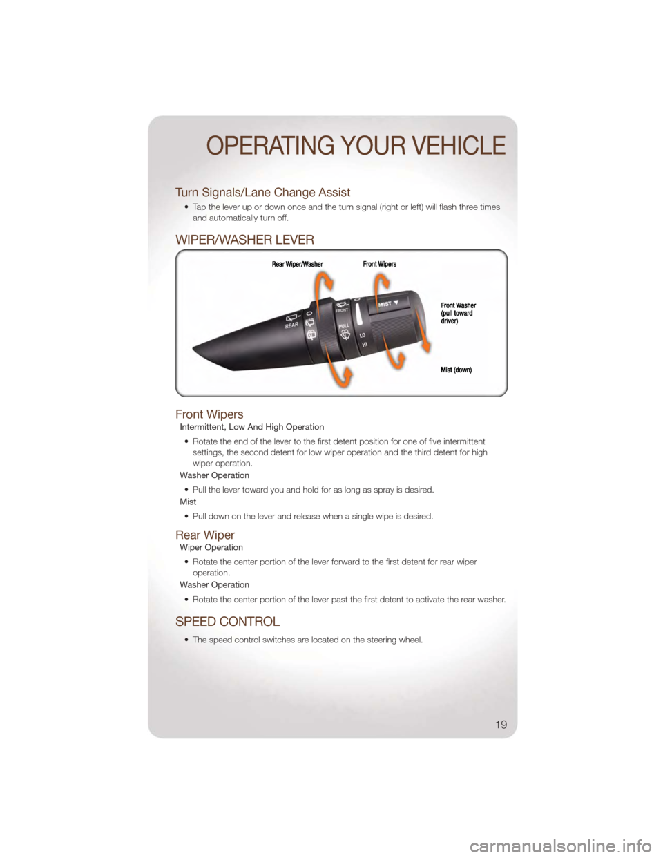
Turn Signals/Lane Change Assist
• Tap the lever up or down once and the turn signal (right or left) will flash three timesand automatically turn off.
WIPER/WASHER LEVER
Front Wipers
Intermittent, Low And High Operation
• Rotate the end of the lever to the first detent position for one of five intermittent settings, the second detent for low wiper operation and the third detent for high
wiper operation.
Washer Operation
• Pull the lever toward you and hold for as long as spray is desired.
Mist
• Pull down on the lever and release when a single wipe is desired.
Rear Wiper
Wiper Operation• Rotate the center portion of the lever forward to the first detent for rear wiper operation.
Washer Operation
• Rotate the center portion of the lever past the first detent to activate the rear washer.
SPEED CONTROL
• The speed control switches are located on the steering wheel.
OPERATING YOUR VEHICLE
19
Page 45 of 88
Mute (Or Unmute) Microphone During Call
• During a call, press the Voice Command button.
• (After the BEEP), say “mute” (or “mute off”).
Transfer Ongoing Call Between Handset And Vehicle
• During a call, press the Voice Command button.
• (After the BEEP), say “transfer call”.
Changing The Volume
• Start a dialogue by pressing the Phone button, then adjust the volume during a
normal call.
• Use the radio ON/OFF VOLUME rotary knob to adjust the volume to a comfortable level while the Uconnect™ system is speaking. Please note the volume setting for
Uconnect™ is different than the audio system.
NOTE: To access the tutorial, press the Uconnect™ hard-key. After the BEEP, say
“tutorial”. Press any hard-key/button or touch the display (Touch-Screen radio) to cancel
the tutorial.
WARNING!
• Any voice commanded system should be used only in safe driving conditions following local laws and phone use. All attention should be kept on the
roadway ahead. Failure to do so may result in a collision causing you and
others to be severely injured or killed.
• In an emergency, to use Uconnect™ Phone, your mobile phone must be: • turned on,
• paired to Uconnect™ Phone,
• and have network coverage.
Uconnect™ VOICE COMMAND
• The Uconnect™ Voice Command system allows you to control your AM, FM radio,satellite radio, disc player, Uconnect™ Phone, a memo recorder, and supported
portable media devices. The Voice Command system also provides limited capability
to select and play music by artist, song, album, music, genre, or playlist from your
compatible iPod
®device (this capability is available for Media Center 430/430N
when connected to the USB port).
• When you press the Voice Command button
located on the radio faceplate
or steering wheel, you will hear a beep. The beep is your signal to give a command.
If you do not say a command within a few seconds, the system will present you with
a list of options. If you ever wish to interrupt the system while it lists options, press
the Voice Command button
, listen for the BEEP, and say your command.
ELECTRONICS
43
Page 49 of 88
Flashing Lights With Lock• The turn signal lights flashing, when the doors are locked or unlocked, feature can be turned on or off. To turn this feature on or off:
• Press and hold the UNLOCK button for at least 4 seconds, but no longer than
10 seconds. Then, press and hold the LOCK button while still holding the
UNLOCK button.
• Release both buttons at the same time.
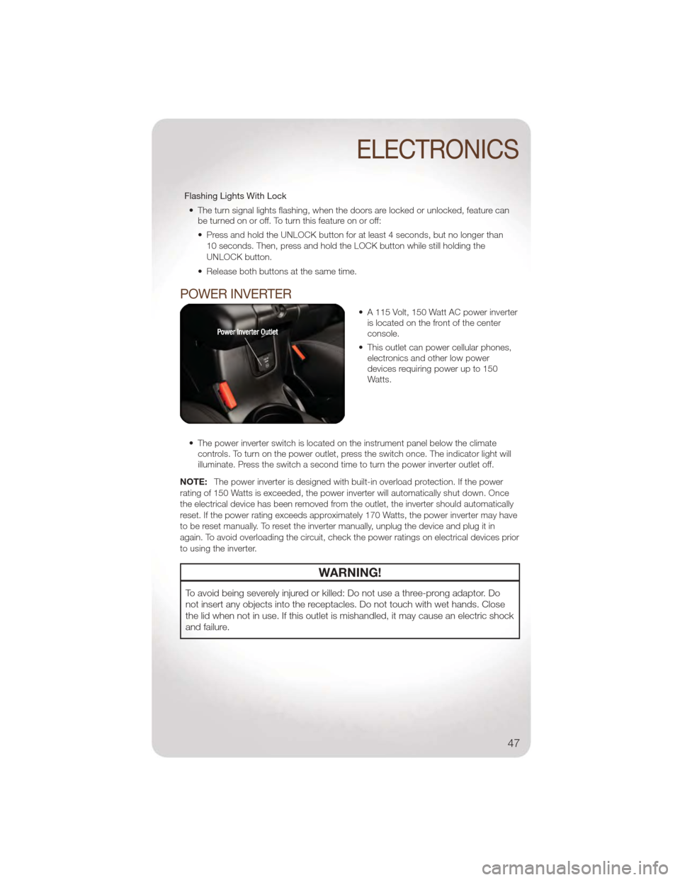
POWER INVERTER
• A 115 Volt, 150 Watt AC power inverter is located on the front of the center
console.
• This outlet can power cellular phones, electronics and other low power
devices requiring power up to 150
Watts.
• The power inverter switch is located on the instrument panel below the climate controls. To turn on the power outlet, press the switch once. The indicator light will
illuminate. Press the switch a second time to turn the power inverter outlet off.
NOTE: The power inverter is designed with built-in overload protection. If the power
rating of 150 Watts is exceeded, the power inverter will automatically shut down. Once
the electrical device has been removed from the outlet, the inverter should automatically
reset. If the power rating exceeds approximately 170 Watts, the power inverter may have
to be reset manually. To reset the inverter manually, unplug the device and plug it in
again. To avoid overloading the circuit, check the power ratings on electrical devices prior
to using the inverter.
WARNING!
To avoid being severely injured or killed: Do not use a three-prong adaptor. Do
not insert any objects into the receptacles. Do not touch with wet hands. Close
the lid when not in use. If this outlet is mishandled, it may cause an electric shock
and failure.
ELECTRONICS
47
Page 57 of 88
• Please note that the TPMS is not a substitute for proper tire maintenance, and it isthe driver’s responsibility to maintain correct tire pressure, even if under-inflation has
not reached the level to trigger illumination of the TPMS low tire pressure telltale.
• Your vehicle has also been equipped with a TPMS malfunction indicator to indicate when the system is not operating properly. The TPMS malfunction indicator is
combined with the low tire pressure telltale. When the system detects a malfunction,
the telltale will flash for approximately one minute and then remain continuously
illuminated. This sequence will continue each time the vehicle is restarted as long as
the malfunction exists.
• When the malfunction indicator is illuminated, the system may not be able to detect or signal low tire pressure as intended. TPMS malfunctions may occur for a variety of
reasons, including the installation of replacement or alternate tires or wheels on the
vehicle that prevent the TPMS from functioning properly. Always check the TPMS
malfunction telltale after replacing one or more tires or wheels on your vehicle, to
ensure that the replacement or alternate tires and wheels allow the TPMS to
continue to function properly.
CAUTION!
The TPMS has been optimized for the original equipment tires and wheels. TPMS
pressures and warning have been established for the tire size equipped on your
vehicle. Undesirable system operation or sensor damage may result when using
replacement equipment that is not of the same size, type, and/or style.
Aftermarket wheels can cause sensor damage. Do not use tire sealant from a
can, or balance beads if your vehicle is equipped with a TPMS, as damage to the
sensors may result.
- Engine Temperature Warning Light
• This light warns of an overheated engine condition.
• If the light turns on and a warning chime sounds while driving, safely pull over andstop the vehicle. If the A/C system is on, turn it off. Also, shift the transmission into
NEUTRAL and idle the vehicle. If the temperature reading does not return to normal,
turn the engine off immediately.
• We recommend that you do not operate the vehicle or engine damage will occur. Have the vehicle serviced immediately.
WARNING!
A hot engine cooling system is dangerous. You or others could be badly burned
by steam or boiling coolant. You may want to call an authorized service center for
service if your vehicle overheats.
WHAT TO DO IN EMERGENCIES
55
Page 79 of 88
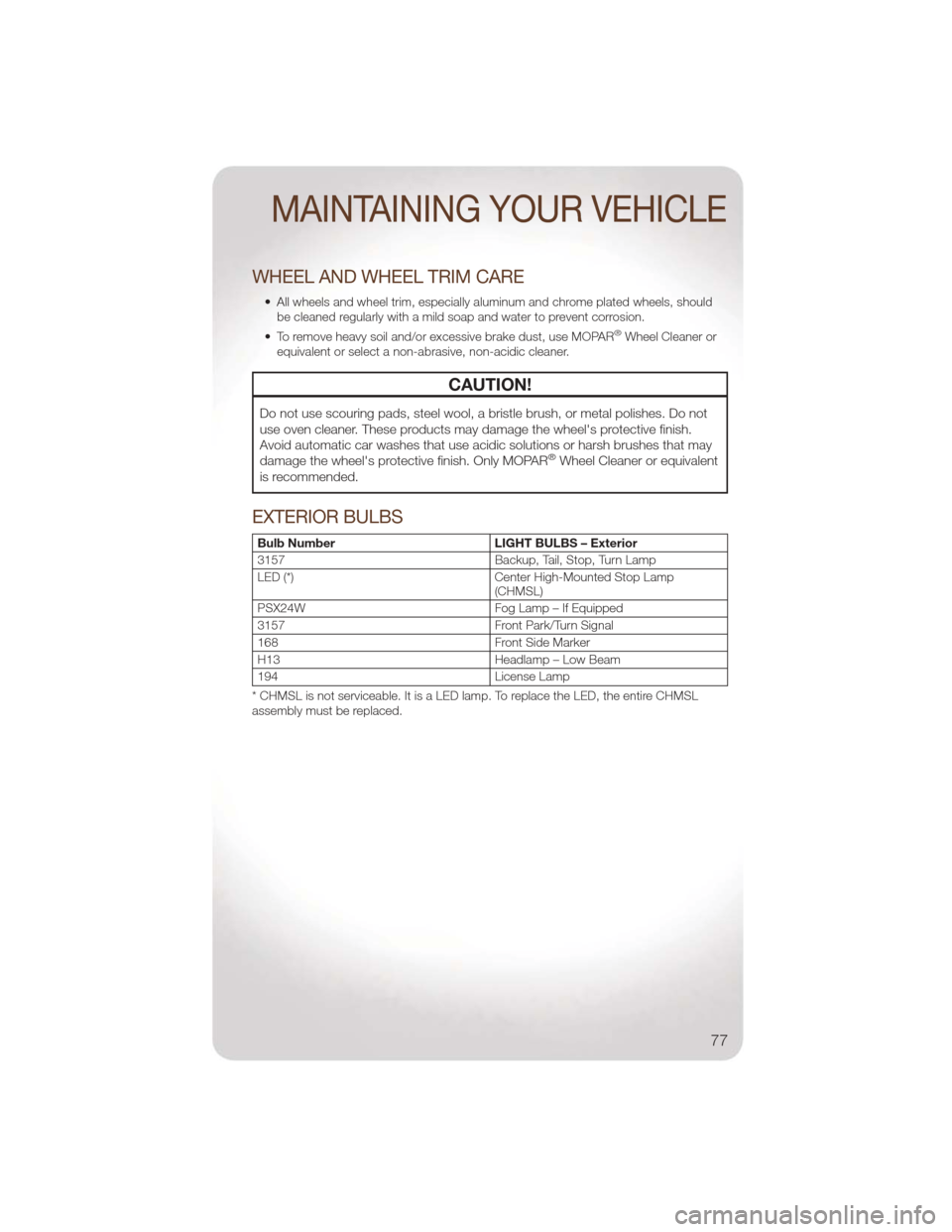
WHEEL AND WHEEL TRIM CARE
• All wheels and wheel trim, especially aluminum and chrome plated wheels, shouldbe cleaned regularly with a mild soap and water to prevent corrosion.
• To remove heavy soil and/or excessive brake dust, use MOPAR
®Wheel Cleaner or
equivalent or select a non-abrasive, non-acidic cleaner.
CAUTION!
Do not use scouring pads, steel wool, a bristle brush, or metal polishes. Do not
use oven cleaner. These products may damage the wheel's protective finish.
Avoid automatic car washes that use acidic solutions or harsh brushes that may
damage the wheel's protective finish. Only MOPAR
®Wheel Cleaner or equivalent
is recommended.
EXTERIOR BULBS
Bulb Number LIGHT BULBS – Exterior
3157 Backup, Tail, Stop, Turn Lamp
LED (*) Center High-Mounted Stop Lamp
(CHMSL)
PSX24W Fog Lamp – If Equipped
3157 Front Park/Turn Signal
168 Front Side Marker
H13 Headlamp – Low Beam
194 License Lamp
* CHMSL is not serviceable. It is a LED lamp. To replace the LED, the entire CHMSL
assembly must be replaced.
MAINTAINING YOUR VEHICLE
77
Page 83 of 88
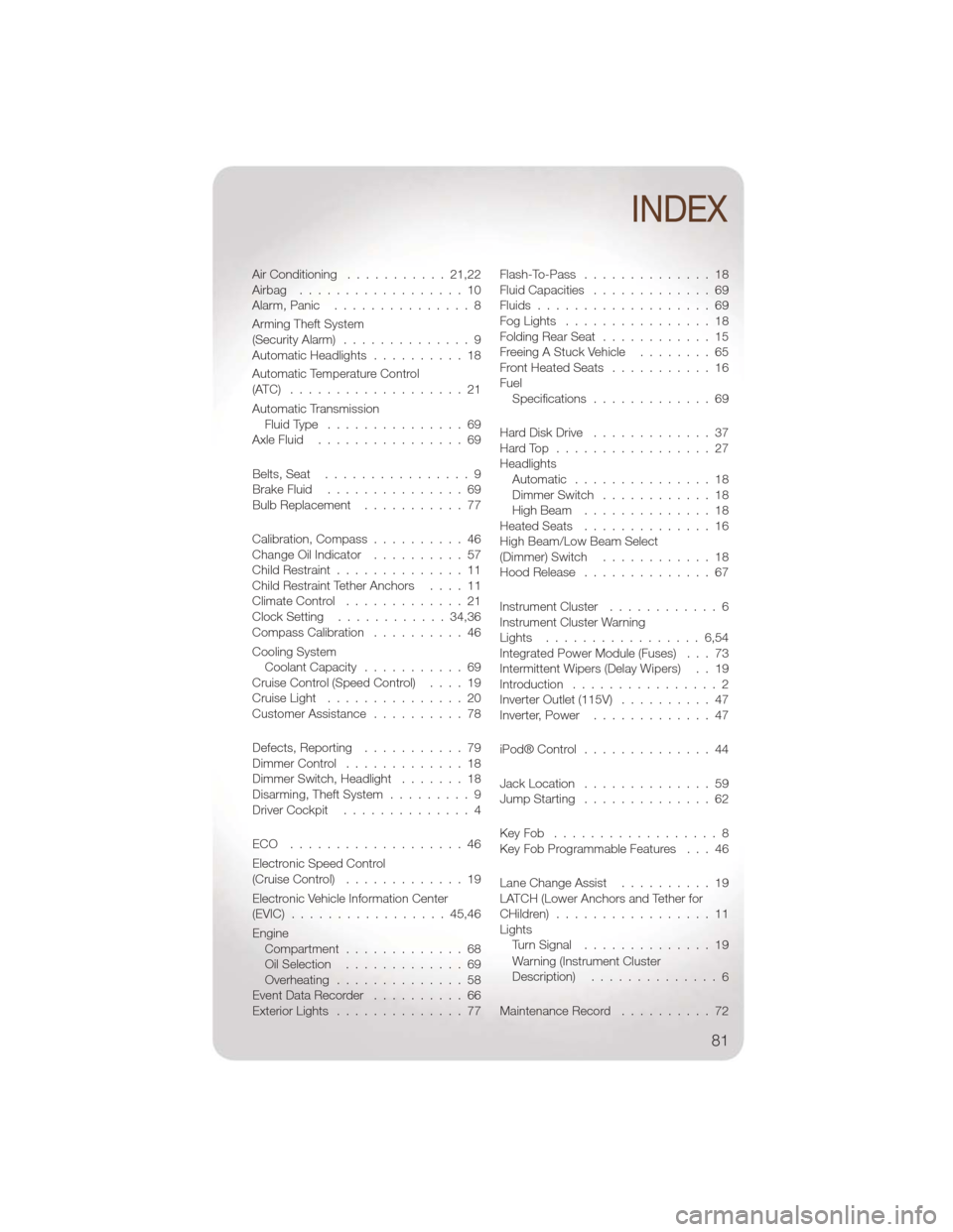
Air Conditioning...........21,22
Airbag ..................10
Alarm,Panic ...............8
Arming Theft System
(Security Alarm) ..............9
AutomaticHeadlights ..........18
Automatic Temperature Control
(ATC) ...................21
Automatic Transmission FluidType ...............69
AxleFluid ................69
Belts, Seat ................9
BrakeFluid ...............69
Bulb Replacement ...........77
Calibration, Compass ..........46
Change Oil Indicator ..........57
Child Restraint ..............11
Child Restraint Tether Anchors ....11
Climate Control .............21
Clock Setting ............34,36
Compass Calibration ..........46
Cooling System Coolant Capacity ...........69
Cruise Control (Speed Control) ....19
CruiseLight ...............20
Customer Assistance ..........78
Defects, Reporting ...........79
Dimmer Control .............18
Dimmer Switch, Headlight .......18
Disarming, Theft System .........9
Driver Cockpit ..............4
ECO ...................46
Electronic Speed Control
(Cruise Control) .............19
Electronic Vehicle Information Center
(EVIC) .................45,46
Engine Compartment .............68
OilSelection .............69
Overheating ..............58
Event Data Recorder ..........66
ExteriorLights ..............77 Flash-To-Pass ..............18
Fluid Capacities
.............69
Fluids ...................69
FogLights ................18
Folding Rear Seat ............15
Freeing A Stuck Vehicle ........65
Front Heated Seats ...........16
Fuel Specifications .............69
Hard Disk Drive .............37
HardTop .................27
Headlights Automatic ...............18
Dimmer Switch ............18
High Beam ..............18
HeatedSeats ..............16
High Beam/Low Beam Select
(Dimmer)Switch ............18
Hood Release ..............67
Instrument Cluster ............6
Instrument Cluster Warning
Lights .................6,54
Integrated Power Module (Fuses) . . . 73
Intermittent Wipers (Delay Wipers) . . 19
Introduction ................2
Inverter Outlet (115V) ..........47
Inverter, Power .............47
iPod® Control ..............44
Jack Location ..............59
Jump Starting ..............62
KeyFob ..................8
Key Fob Programmable Features . . . 46
Lane Change Assist ..........19
LATCH (Lower Anchors and Tether for
CHildren) .................11
Lights TurnSignal ..............19
Warning (Instrument Cluster
Description) ..............
6
Maintenance Record ..........72
INDEX
81