service JEEP WRANGLER 2020 Owner handbook (in English)
[x] Cancel search | Manufacturer: JEEP, Model Year: 2020, Model line: WRANGLER, Model: JEEP WRANGLER 2020Pages: 276, PDF Size: 4.47 MB
Page 67 of 276
If any of these systems require service, the
OBD II system will turn on the Malfunction
Indicator Light (MIL). It will also store diag-
nostic codes and other information to assist
your service technician in making repairs.
Although your vehicle will usually be drivable
and not need towing, see your authorized
dealer for service as soon as possible.
CAUTION!
• Prolonged driving with the MIL on could
cause further damage to the emission
control system. It could also affect fuel
economy and driveability. The vehicle
must be serviced before any emissions
tests can be performed.
• If the MIL is flashing while the vehicle is
running, severe catalytic converter dam-
age and power loss will soon occur. Im-
mediate service is required.
Onboard Diagnostic System (OBD II)
Cybersecurity
Your vehicle is required to have an Onboard
Diagnostic system (OBD II) and a connection
port to allow access to information related tothe performance of your emissions controls.
Authorized service technicians may need to
access this information to assist with the
diagnosis and service of your vehicle and
emissions system.
WARNING!
• ONLY an authorized service technician
should connect equipment to the OBD II
connection port in order to diagnose or
service your vehicle.
• If unauthorized equipment is connected
to the OBD II connection port, such as a
driver-behavior tracking device, it may:
• Be possible that vehicle systems,
including safety related systems,
could be impaired or a loss of ve-
hicle control could occur that may
result in an accident involving seri-
ous injury or death.
• Access, or allow others to access,
information stored in your vehicle
systems, including personal infor-
mation.For further information, refer to “Cybersecu-
rity” in “Multimedia” in your Owner's
Manual.
Loose Fuel Filler Cap Message
After fuel is added, the vehicle diagnostic
system can determine if the fuel filler cap is
possibly loose, improperly installed, or dam-
aged. A “gASCAP” message will be displayed
in the odometer. Tighten the gas cap until a
"clicking" sound is heard. This is an indica-
tion that the gas cap is properly tightened.
Push the odometer reset button to turn the
message off. If the problem persists, the
message will appear the next time the vehicle
is started. This might indicate a damaged
cap. If the problem is detected twice in a row,
the system will turn on the MIL. Resolving the
problem will turn the MIL off.
65
Page 70 of 276
SAFETY FEATURES
Anti-Lock Brake System (ABS)
The Anti-Lock Brake System (ABS) provides
increased vehicle stability and brake perfor-
mance under most braking conditions. The
system automatically prevents wheel lock,
and enhances vehicle control during braking.
The ABS performs a self-check cycle to en-
sure that the ABS is working properly each
time the vehicle is started and driven. During
this self-check, you may hear a slight clicking
sound as well as some related motor noises.
ABS is activated during braking when the
system detects one or more wheels begin to
lock. Road conditions such as ice, snow,
gravel, bumps, railroad tracks, loose debris,
or panic stops may increase the likelihood of
ABS activation(s).
You also may experience the following when
ABS activates:
• The ABS motor noise (it may continue to
run for a short time after the stop).
• The clicking sound of solenoid valves.• Brake pedal pulsations.
• A slight drop of the brake pedal at the end
of the stop.
These are all normal characteristics of ABS.
WARNING!
• The ABS contains sophisticated elec-
tronic equipment that may be suscep-
tible to interference caused by improp-
erly installed or high output radio
transmitting equipment. This interfer-
ence can cause possible loss of anti-lock
braking capability. Installation of such
equipment should be performed by
qualified professionals.
• Pumping of the Anti-Lock Brakes will
diminish their effectiveness and may
lead to a collision. Pumping makes the
stopping distance longer. Just press
firmly on your brake pedal when you
need to slow down or stop.
• The ABS cannot prevent the natural laws
of physics from acting on the vehicle,
nor can it increase braking or steering
efficiency beyond that afforded by the
WARNING!
condition of the vehicle brakes and tires
or the traction afforded.
• The ABS cannot prevent collisions, in-
cluding those resulting from excessive
speed in turns, following another vehicle
too closely, or hydroplaning.
• The capabilities of an ABS equipped
vehicle must never be exploited in a
reckless or dangerous manner that could
jeopardize the user’s safety or the safety
of others.
ABS is designed to function with the OEM
tires. Modification may result in degraded
ABS performance.
Anti-Lock Brake Warning Light
The yellow “Anti-Lock Brake Warning Light”
will turn on when the ignition is turned to the
ON/RUN mode and may stay on for as long as
four seconds.
If the “Anti-Lock Brake Warning Light” re-
mains on or comes on while driving, it indi-
cates that the anti-lock portion of the brake
system is not functioning and that service is
SAFETY
68
Page 71 of 276
required. However, the conventional brake
system will continue to operate normally if
the “Brake System Warning Light” is not on.
If the “Anti-Lock Brake Warning Light” is on,
the brake system should be serviced as soon
as possible to restore the benefits of anti-lock
brakes. If the “Anti-Lock Brake Warning
Light” does not come on when the ignition is
turned to the ON/RUN mode, have the light
repaired as soon as possible.
Electronic Brake Control System
Your vehicle is equipped with an advanced
Electronic Brake Control system (EBC). This
system includes Electronic Brake Force Dis-
tribution (EBD), Brake Assist System (BAS),
Hill Start Assist (HSA), Traction Control Sys-
tem (TCS), Electronic Stability Control
(ESC), and Electronic Roll Mitigation (ERM).
These systems work together to enhance both
vehicle stability and control in various driving
conditions.
Your vehicle may also be equipped with
Trailer Sway Control (TSC) and Hill Descent
Control (HDC).
Electronic Brake Force Distribution (EBD)
This function manages the distribution of the
braking torque between the front and rear
axles by limiting braking pressure to the rear
axle. This is done to prevent overslip of the
rear wheels to avoid vehicle instability, and to
prevent the rear axle from entering ABS be-
fore the front axle.
Brake System Warning Light
The red “Brake System Warning Light” will
turn on when the ignition is turned to the
ON/RUN mode and may stay on for as long as
four seconds.
If the “Brake System Warning Light” remains
on or comes on while driving, it indicates that
the brake system is not functioning properly
and that immediate service is required. If the
“Brake System Warning Light” does not
come on when the ignition is turned to the
ON/RUN mode, have the light repaired as
soon as possible.
Brake Assist System (BAS)
The BAS is designed to optimize the vehicle’s
braking capability during emergency braking
maneuvers. The system detects an emer-
gency braking situation by sensing the rate
and amount of brake application and then
applies optimum pressure to the brakes. This
can help reduce braking distances. The BAS
complements the anti-lock brake system
(ABS). Applying the brakes very quickly re-
sults in the best BAS assistance. To receive
the benefit of the system, you must apply
continuous braking pressure during the stop-
ping sequence, (do not “pump” the brakes).
Do not reduce brake pedal pressure unless
braking is no longer desired. Once the brake
pedal is released, the BAS is deactivated.
WARNING!
The Brake Assist System (BAS) cannot
prevent the natural laws of physics from
acting on the vehicle, nor can it increase
the traction afforded by prevailing road
conditions. BAS cannot prevent collisions,
including those resulting from excessive
69
Page 84 of 276
will no longer be highlighted or shown in a
different color and the Tire Pressure Monitor-
ing Telltale Light will extinguish once the
updated tire pressure(s) have been received.
NOTE:
When filling warm tires, the tire pressure may
need to be increased up to an additional 4 psi
(30 kPa) above the recommended cold plac-
ard pressure in order to turn the Tire Pressure
Monitoring Telltale Light off.
The vehicle may need to be driven for up to
10 minutes above 15 mph (24 km/h) to
receive this information.
Service TPM System Warning
The “Tire Pressure Monitoring Telltale Light”
will flash on and off for 75 seconds, and
remain on solid when a system fault is de-
tected. The system fault will also sound a
chime. The instrument cluster will display a
“SERVICE TPM SYSTEM” message for a
minimum of five seconds. This message is
then followed by a graphic display, with “- -“
in place of the pressure value(s), indicating
which Tire Pressure Monitoring Sensor(s) is
not being received.If the ignition switch is cycled, this sequence
will repeat, providing the system fault still
exists. If the system fault no longer exists, the
“Tire Pressure Monitoring Telltale Light” will
no longer flash, the "SERVICE TPM SYSTEM"
message will not be present, and a pressure
value will be displayed instead of dashes. A
system fault can occur by any of the follow-
ing:
• Jamming due to electronic devices or driv-
ing next to facilities emitting the same
Radio Frequencies as the TPM sensors.
• Installing some form of aftermarket window
tinting that affects radio wave signals.
• Lots of snow or ice around the wheels or
wheel housings.
• Using tire chains on the vehicle.
• Using wheels/tires not equipped with TPM
sensors.
NOTE:
• If your vehicle is equipped with a matching
full-size spare wheel and tire assembly, it
has a tire pressure monitoring sensor, and
can be monitored by the Tire Pressure
Monitoring System (TPMS) when swappedwith a low pressure road tire. In the event
that the matching full-size spare tire is
swapped with a low pressure road tire, the
next ignition switch cycle will still show the
“Tire Pressure Monitoring Telltale Light” to
be ON, a chime to sound, a “LOW TIRE”
message to appear in the instrument clus-
ter, and the graphic display will still show
the low tire pressure value highlighted or
shown in a different color. Driving the ve-
hicle for up to 10 minutes above 15 mph
(24 km/h) will turn OFF the “Tire Pressure
Monitoring Telltale Light” as long as none
of road tires are below the low pressure
warning threshold.
• If your vehicle is not equipped with a
matching full-size spare wheel and tire as-
sembly, it does not have a tire pressure
monitoring sensor in the spare tire. The
TPMS will not be able to monitor the tire
pressure. If you install the spare tire in
place of a road tire that has a pressure
below the low-pressure warning limit, upon
the next ignition switch cycle, the “Tire
Pressure Monitoring Telltale Light” will re-
main ON, a chime will sound, and the
instrument cluster will still display a high-
lighted or different color pressure value in
SAFETY
82
Page 85 of 276
the graphic display. After driving the ve-
hicle for up to 10 minutes above 15 mph
(24 km/h), the “Tire Pressure Monitoring
Telltale Light” will flash on and off for
75 seconds and then remain on solid. In
addition, the instrument cluster will display
a “SERVICE TPM SYSTEM" message for a
minimum of five seconds and then display
dashes (- -) in place of the pressure value.
For each subsequent ignition switch cycle,
a chime will sound, the “Tire Pressure
Monitoring Telltale Light” will flash on and
off for 75 seconds and then remain on
solid, and the instrument cluster will dis-
play a "SERVICE TPM SYSTEM" message
for a minimum of five seconds and then
display dashes (- -) in place of the pressure
value.
• Once you repair or replace the original road
tire, and reinstall it on the vehicle in place
of the spare tire, the TPMS will update
automatically.
In addition, the “Tire Pressure Monitoring Tell-
tale Light” will turn OFF and the graphic in the
instrument cluster will display a new pressure
value instead of dashes (- -), as long as no tire
pressure is below the low-pressure warninglimit in any of the four active road tires. The
vehicle may need to be driven for up to 10 min-
utes above 15 mph (24 km/h) in order for the
TPMS to receive this information.
TPMS Deactivation — If Equipped
The TPMS can be deactivated if replacing all
four wheel and tire assemblies (road tires)
with wheel and tire assemblies that do not
have TPMS Sensors, such as when installing
winter wheel and tire assemblies on your
vehicle.
To deactivate the TPMS, first, replace all four
wheel and tire assemblies (road tires) with
tires not equipped with Tire Pressure Moni-
toring (TPM) Sensors. Then, drive the vehicle
for 10 minutes above 15 mph (24 km/h). The
TPMS will chime, the "TPM Telltale Light"
will flash on and off for 75 seconds and then
remain on. The instrument cluster will dis-
play the “SERVICE TPM SYSTEM” message
and then display dashes (--) in place of the
pressure values.Beginning with the next ignition cycle, the
TPMS will no longer chime or display the
“SERVICE TPM SYSTEM” message in the
instrument cluster but dashes (--) will remain
in place of the pressure values.
To reactivate the TPMS, replace all four
wheel and tire assemblies (road tires) with
tires equipped with TPM sensors. Then, drive
the vehicle for up to 10 minutes above
15 mph (24 km/h). The TPMS will chime, the
"TPM Telltale Light" will flash on and off for
75 seconds and then turn off. The instrument
cluster will display the “SERVICE TPM SYS-
TEM” message and then display pressure
values in place of the dashes. On the next
ignition cycle the "SERVICE TPM SYSTEM"
message will no longer be displayed as long
as no system fault exists.
83
Page 87 of 276
8. Do not lean against the door or window. If
your vehicle has side air bags, and deploy-
ment occurs, the side air bags will inflate
forcefully into the space between occu-
pants and the door and occupants could
be injured.
9. If the air bag system in this vehicle needs
to be modified to accommodate a dis-
abled person, refer to the “Customer As-
sistance” section for customer service
contact information.
WARNING!
• NEVER use a rearward facing child re-
straint on a seat protected by an ACTIVE
AIRBAG in front of it, DEATH or SERI-
OUS INJURY to the CHILD can occur.
• Only use a rear-facing child restraint in a
vehicle with a rear seat.
• A deploying passenger front air bag can
cause death or serious injury to a child
12 years or younger, including a child in
a rear-facing child restraint.
Seat Belt Systems
Buckle up even though you are an excellent
driver, even on short trips. Someone on the
road may be a poor driver and could cause a
collision that includes you. This can happen
far away from home or on your own street.
Research has shown that seat belts save
lives, and they can reduce the seriousness of
injuries in a collision. Some of the worst
injuries happen when people are thrown from
the vehicle. Seat belts reduce the possibility
of ejection and the risk of injury caused by
striking the inside of the vehicle. Everyone in
a motor vehicle should be belted at all times.
Enhanced Seat Belt Use Reminder System
(BeltAlert)
Driver And Passenger BeltAlert — If Equipped
BeltAlert is a feature intended to remind
the driver and outboard front seat passenger (if
equipped with outboard front passenger seat
BeltAlert) to buckle their seat belts. The Belt
Alert feature is active whenever the ignition
switch is in the START or ON/RUN position.
Initial Indication
If the driver is unbuckled when the ignition
switch is first in the START or ON/RUN posi-
tion, a chime will signal for a few seconds. If
the driver or outboard front seat passenger (if
equipped with outboard front passenger seat
BeltAlert) is unbuckled when the ignition
switch is first in the START or ON/RUN posi-
tion the Seat Belt Reminder Light will turn on
and remain on until both outboard front seat
belts are buckled. The outboard front passen-
ger seat BeltAlert is not active when an out-
board front passenger seat is unoccupied.
BeltAlert Warning Sequence
The BeltAlert warning sequence is activated
when the vehicle is moving above a specified
vehicle speed range and the driver or out-
board front seat passenger is unbuckled (if
equipped with outboard front passenger seat
BeltAlert) (the outboard front passenger seat
BeltAlert is not active when the outboard
front passenger seat is unoccupied). The
BeltAlert warning sequence starts by blinking
the Seat Belt Reminder Light and sounding
an intermittent chime. Once the BeltAlert
warning sequence has completed, the Seat
85
Page 91 of 276
WARNING!
If the rear seatback is not fully upright and
locked and the rear center lap/shoulder
belt can be pulled out of the retractor,
immediately take the vehicle to your au-
thorized dealer for service. Failure to fol-
low this warning could result in serious
injury or death.
Lap/Shoulder Belt Untwisting Procedure
Use the following procedure to untwist a
twisted lap/shoulder belt.
1. Position the latch plate as close as pos-
sible to the anchor point.
2. At about 6 to 12 inches (15 to 30 cm)
above the latch plate, grasp and twist the
seat belt webbing 180 degrees to create a
fold that begins immediately above the
latch plate.
3. Slide the latch plate upward over the
folded webbing. The folded webbing must
enter the slot at the top of the latch plate.
4. Continue to slide the latch plate up until it
clears the folded webbing and the seat
belt is no longer twisted.
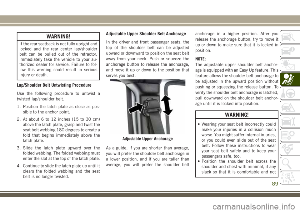
Adjustable Upper Shoulder Belt Anchorage
In the driver and front passenger seats, the
top of the shoulder belt can be adjusted
upward or downward to position the seat belt
away from your neck. Push or squeeze the
anchorage button to release the anchorage,
and move it up or down to the position that
serves you best.
As a guide, if you are shorter than average,
you will prefer the shoulder belt anchorage in
a lower position, and if you are taller than
average, you will prefer the shoulder beltanchorage in a higher position. After you
release the anchorage button, try to move it
up or down to make sure that it is locked in
position.
NOTE:
The adjustable upper shoulder belt anchor-
age is equipped with an Easy Up feature. This
feature allows the shoulder belt anchorage to
be adjusted in the upward position without
pushing or squeezing the release button. To
verify the shoulder belt anchorage is latched,
pull downward on the shoulder belt anchor-
age until it is locked into position.
WARNING!
• Wearing your seat belt incorrectly could
make your injuries in a collision much
worse. You might suffer internal injuries,
or you could even slide out of the seat
belt. Follow these instructions to wear
your seat belt safely and to keep your
passengers safe, too.
• Position the shoulder belt across the
shoulder and chest with minimal, if any
slack so that it is comfortable and not
Adjustable Upper Anchorage
89
Page 94 of 276
How To Disengage The Automatic Locking Mode
Unbuckle the combination lap/shoulder belt
and allow it to retract completely to disen-
gage the Automatic Locking Mode and acti-
vate the vehicle sensitive (emergency) lock-
ing mode.
WARNING!
• The seat belt assembly must be replaced
if the switchable Automatic Locking Re-
tractor (ALR) feature or any other seat
belt function is not working properly
when checked according to the proce-
dures in the Service Manual.
• Failure to replace the seat belt assembly
could increase the risk of injury in colli-
sions.
• Do not use the Automatic Locking Mode
to restrain occupants who are wearing
the seat belt or children who are using
booster seats. The locked mode is only
used to install rear-facing or forward-
facing child restraints that have a har-
ness for restraining the child.
Supplemental Restraint Systems (SRS)
Some of the safety features described in this
section may be standard equipment on some
models, or may be optional equipment on
others. If you are not sure, ask your autho-
rized dealer.
The air bag system must be ready to protect
you in a collision. The Occupant Restraint
Controller (ORC) monitors the internal cir-
cuits and interconnecting wiring associated
with the electrical Air Bag System Compo-
nents. Your vehicle may be equipped with the
following Air Bag System Components:
Air Bag System Components
•Occupant Restraint Controller (ORC)
•Air Bag Warning Light
•Steering Wheel and Column
•Instrument Panel
•Knee Impact Bolsters
•Driver and Front Passenger Air Bags
•Seat Belt Buckle Switch
•Supplemental Side Air Bags
•Front and Side Impact Sensors
•Seat Belt Pretensioners
Air Bag Warning Light
The ORC monitors the readiness of the
electronic parts of the air bag system when-
ever the ignition switch is in the START or
ON/RUN position. If the ignition switch is in
the OFF position or in the ACC position, the
air bag system is not on and the air bags will
not inflate.
The ORC contains a backup power supply
system that may deploy the air bag system
even if the battery loses power or it becomes
disconnected prior to deployment.
The ORC turns on the Air Bag Warning Light
in the instrument panel for approximately
four to eight seconds for a self-check when
the ignition switch is first in the ON/RUN
position. After the self-check, the Air Bag
Warning Light will turn off. If the ORC detects
a malfunction in any part of the system, it
turns on the Air Bag Warning Light, either
momentarily or continuously. A single chime
will sound to alert you if the light comes on
again after initial startup.
SAFETY
92
Page 95 of 276
The ORC also includes diagnostics that will
illuminate the instrument panel Air Bag
Warning Light if a malfunction is detected
that could affect the air bag system. The
diagnostics also record the nature of the
malfunction. While the air bag system is
designed to be maintenance free, if any of the
following occurs, have an authorized dealer
service the air bag system immediately.
• The Air Bag Warning Light does not come
on during the four to eight seconds when
the ignition switch is first in the ON/RUN
position.
• The Air Bag Warning Light remains on after
the four to eight-second interval.
• The Air Bag Warning Light comes on inter-
mittently or remains on while driving.
NOTE:
If the speedometer, tachometer, or any en-
gine related gauges are not working, the Oc-
cupant Restraint Controller (ORC) may also
be disabled. In this condition the air bags
may not be ready to inflate for your protec-
tion. Have an authorized dealer service the air
bag system immediately.WARNING!
Ignoring the Air Bag Warning Light in your
instrument panel could mean you won’t
have the air bag system to protect you in a
collision. If the light does not come on as a
bulb check when the ignition is first turned
on, stays on after you start the vehicle, or if
it comes on as you drive, have an autho-
rized dealer service the air bag system
immediately.
Front Air Bags
This vehicle has front air bags and lap/
shoulder belts for both the driver and front
passenger. The front air bags are a supple-
ment to the seat belt restraint systems. The
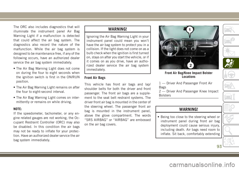
driver front air bag is mounted in the center of
the steering wheel. The passenger front air
bag is mounted in the instrument panel,
above the glove compartment. The words
“SRS AIRBAG” or “AIRBAG” are embossed
on the air bag covers.
WARNING!
• Being too close to the steering wheel or
instrument panel during front air bag
deployment could cause serious injury,
including death. Air bags need room to
inflate. Sit back, comfortably extending
Front Air Bag/Knee Impact Bolster
Locations
1 — Driver And Passenger Front Air
Bags
2 — Driver And Passenger Knee Impact
Bolsters
93
Page 99 of 276
WARNING!
some collisions, Side Air Bags won’t
deploy at all. Always wear your seat belt
even though you have Side Air Bags.
NOTE:
Air bag covers may not be obvious in the
interior trim, but they will open during air bag
deployment.
Air Bag System Components
The Occupant Restraint Controller (ORC)
monitors the internal circuits and intercon-
necting wiring associated with electrical Air
Bag System Components listed below:
• Occupant Restraint Controller (ORC)
• Air Bag Warning Light
• Steering Wheel and Column
• Instrument Panel
• Knee Impact Bolsters
• Driver and Front Passenger Air Bags
• Seat Belt Buckle Switch
• Supplemental Side Air Bags• Front and Side Impact Sensors
• Seat Belt Pretensioners
If A Deployment Occurs
The front air bags are designed to deflate
immediately after deployment.
NOTE:
Front and/or side air bags will not deploy in all
collisions. This does not mean something is
wrong with the air bag system.
If you do have a collision which deploys the
air bags, any or all of the following may occur:
• The air bag material may sometimes cause
abrasions and/or skin reddening to the oc-
cupants as the air bags deploy and unfold.
The abrasions are similar to friction rope
burns or those you might get sliding along a
carpet or gymnasium floor. They are not
caused by contact with chemicals. They are
not permanent and normally heal quickly.
However, if you haven’t healed significantly
within a few days, or if you have any blis-
tering, see your doctor immediately.
• As the air bags deflate, you may see some
smoke-like particles. The particles are a
normal by-product of the process that gen-erates the non-toxic gas used for air bag
inflation. These airborne particles may irri-
tate the skin, eyes, nose, or throat. If you
have skin or eye irritation, rinse the area
with cool water. For nose or throat irritation,
move to fresh air. If the irritation continues,
see your doctor. If these particles settle on
your clothing, follow the garment manufac-
turer’s instructions for cleaning.
Do not drive your vehicle after the air bags
have deployed. If you are involved in another
collision, the air bags will not be in place to
protect you.
WARNING!
Deployed air bags and seat belt preten-
sioners cannot protect you in another col-
lision. Have the air bags, seat belt preten-
sioners, and the seat belt retractor
assemblies replaced by an authorized
dealer immediately. Also, have the Occu-
pant Restraint Controller System serviced
as well.
97