service JEEP WRANGLER 2020 Owner handbook (in English)
[x] Cancel search | Manufacturer: JEEP, Model Year: 2020, Model line: WRANGLER, Model: JEEP WRANGLER 2020Pages: 276, PDF Size: 4.47 MB
Page 100 of 276
NOTE:
• Air bag covers may not be obvious in the
interior trim, but they will open during air
bag deployment.
• After any collision, the vehicle should be
taken to an authorized dealer immediately.
Enhanced Accident Response System
In the event of an impact, if the communica-
tion network remains intact, and the power
remains intact, depending on the nature of
the event, the ORC will determine whether to
have the Enhanced Accident Response Sys-
tem perform the following functions:
• Cut off fuel to the engine.
• Flash hazard lights as long as the battery
has power or until the hazard light button is
pressed. The hazard lights can be deacti-
vated by pressing the hazard light button.
• Turn on the interior lights, which remain on
as long as the battery has power.
• Unlock the power door locks.
Enhanced Accident Response System Reset
Procedure
In order to reset the Enhanced Accident Re-
sponse System functions after an event, the
ignition switch must be changed from igni-
tion START or ON/RUN to ignition OFF. Care-
fully check the vehicle for fuel leaks in the
engine compartment and on the ground near
the engine compartment and fuel tank before
resetting the system and starting the engine.
Maintaining Your Air Bag System
WARNING!
• Modifications to any part of the air bag
system could cause it to fail when you
need it. You could be injured if the air
bag system is not there to protect you.
Do not modify the components or wiring,
including adding any kind of badges or
stickers to the steering wheel hub trim
cover or the upper right side of the
instrument panel. Do not modify the
front bumper, vehicle body structure, or
add aftermarket side steps or running
boards.
WARNING!
• It is dangerous to try to repair any part of
the air bag system yourself. Be sure to
tell anyone who works on your vehicle
that it has an air bag system.
• Do not attempt to modify any part of your
air bag system. The air bag may inflate
accidentally or may not function prop-
erly if modifications are made. Take your
vehicle to an authorized dealer for any
air bag system service. If your seat, in-
cluding your trim cover and cushion,
needs to be serviced in any way (includ-
ing removal or loosening/tightening of
seat attachment bolts), take the vehicle
to your authorized dealer. Only manufac-
turer approved seat accessories may be
used. If it is necessary to modify the air
bag system for persons with disabilities,
contact your authorized dealer.
Event Data Recorder (EDR)
This vehicle is equipped with an event data
recorder (EDR). The main purpose of an EDR
is to record, in certain crash or near crash-
like situations, such as an air bag deployment
SAFETY
98
Page 115 of 276
addition, inspect the exhaust system each
time the vehicle is raised for lubrication or oil
change. Replace as required.
Safety Checks You Should Make Inside
The Vehicle
Seat Belts
Inspect the seat belt system periodically,
checking for cuts, frays, and loose parts. Dam-
aged parts must be replaced immediately. Do
not disassemble or modify the system.
Front seat belt assemblies must be replaced
after a collision. Rear seat belt assemblies
must be replaced after a collision if they have
been damaged (i.e., bent retractor, torn web-
bing, etc.). If there is any question regarding
seat belt or retractor condition, replace the
seat belt.
Air Bag Warning Light
The Air Bag warning lightwill turn on for
four to eight seconds as a bulb check when the
ignition switch is first turned to ON/RUN. If the
light is either not on during starting, stays on, or
turns on while driving, have the system in-spected at an authorized dealer as soon as
possible. This light will illuminate with a single
chime when a fault with the Air Bag Warning
Light has been detected, it will stay on until the
fault is removed. If the light comes on intermit-
tently or remains on while driving, have an
authorized dealer service the vehicle immedi-
ately. Refer to “Occupant Restraint Systems” in
“Safety” for further information.
Defroster
Check operation by selecting the defrost
mode and place the blower control on high
speed. You should be able to feel the air
directed against the windshield. See your
authorized dealer for service if your defroster
is inoperable.
Floor Mat Safety Information
Always use floor mats designed to fit your
vehicle. Only use a floor mat that does not
interfere with the operation of the pedal as-
semblies. Only use a floor mat that is securely
attached using the floor mat fasteners so it
cannot slip out of position and interfere with
the pedal assemblies or impair safe operation
of your vehicle in other ways.
WARNING!
An improperly attached, damaged, folded,
or stacked floor mat, or damaged floor mat
fasteners may cause your floor mat to in-
terfere with the accelerator, brake, or
clutch pedals and cause a loss of vehicle
control. To prevent SERIOUS INJURY or
DEATH:
• ALWAYS securely attach
your floor
mat using the floor mat fasteners. DO
NOT install your floor mat upside down
or turn your floor mat over. Lightly pull to
confirm mat is secured using the floor
mat fasteners on a regular basis.
• ALWAYS REMOVE THE EXISTING
FLOOR MAT FROM THE VEHICLE
before installing any other floor mat.
NEVER install or stack an additional
floor mat on top of an existing floor mat.
• ONLY install floor mats designed to fit
your vehicle. NEVER install a floor mat
that cannot be properly attached and
secured to your vehicle. If a floor mat
needs to be replaced, only use a FCA
approved floor mat for the specific
make, model, and year of your vehicle.
113
Page 123 of 276
ENGINE BREAK-IN
RECOMMENDATIONS
A long break-in period is not required for the
engine and drivetrain (transmission and axle)
in your vehicle.
Drive moderately during the first 300 miles
(500 km). After the initial 60 miles
(100 km), speeds up to 50 or 55 mph (80 or
90 km/h) are desirable.
While cruising, brief full-throttle acceleration
within the limits of local traffic laws contrib-
utes to a good break-in. Wide-open throttle
acceleration in low gear can be detrimental
and should be avoided.
The engine oil installed in the engine at the
factory is a high-quality energy conserving
type lubricant. Oil changes should be consis-
tent with anticipated climate conditions un-
der which vehicle operations will occur. For
the recommended viscosity and quality
grades, refer to “Dealer Service” in “Servic-
ing And Maintenance”.
CAUTION!
Never use Non-Detergent Oil or Straight
Mineral Oil in the engine or damage may
result.
NOTE:
A new engine may consume some oil during
its first few thousand miles (kilometers) of
operation. This should be considered a nor-
mal part of the break-in and not interpreted
as a problem.
PARKING BRAKE
Before exiting the vehicle, make sure that the
parking brake is fully applied. Also, be cer-
tain to leave an automatic transmission in
PARK, or manual transmission in REVERSE
or FIRST gear.
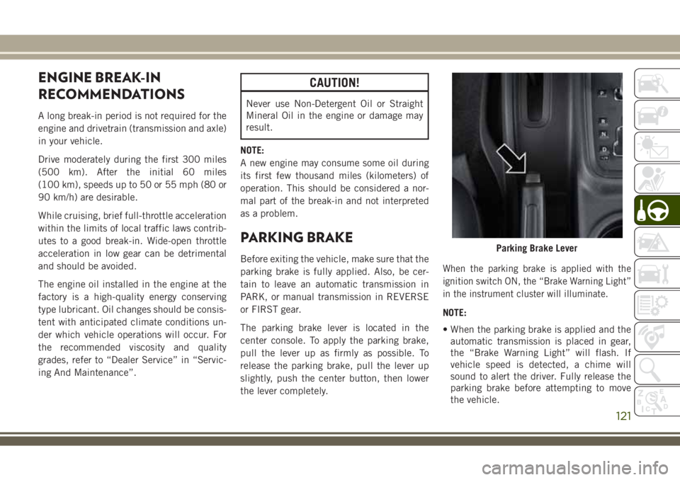
The parking brake lever is located in the
center console. To apply the parking brake,
pull the lever up as firmly as possible. To
release the parking brake, pull the lever up
slightly, push the center button, then lower
the lever completely.When the parking brake is applied with the
ignition switch ON, the “Brake Warning Light”
in the instrument cluster will illuminate.
NOTE:
• When the parking brake is applied and the
automatic transmission is placed in gear,
the “Brake Warning Light” will flash. If
vehicle speed is detected, a chime will
sound to alert the driver. Fully release the
parking brake before attempting to move
the vehicle.
Parking Brake Lever
121
Page 124 of 276
• This light only shows that the parking brake
is applied. It does not show the degree of
brake application.
When parking on a hill, it is important to turn
the front wheels toward the curb on a down-
hill grade and away from the curb on an uphill
grade. For vehicles equipped with an auto-
matic transmission, apply the parking brake
before placing the gear selector in PARK,
otherwise the load on the transmission lock-
ing mechanism may make it difficult to move
the gear selector out of PARK. The parking
brake should always be applied whenever the
driver is not in the vehicle.
WARNING!
• Never use the PARK position on an au-
tomatic transmission as a substitute for
the parking brake. Always apply the
parking brake fully when parked to guard
WARNING!
against vehicle movement and possible
injury or damage.
• When exiting the vehicle, always remove
the key fob from the ignition and lock
your vehicle.
• Never leave children alone in a vehicle,
or with access to an unlocked vehicle.
Allowing children to be in a vehicle un-
attended is dangerous for a number of
reasons. A child or others could be seri-
ously or fatally injured. Children should
be warned not to touch the parking
brake, brake pedal or the gear selector.
• Do not leave the key fob in or near the
vehicle, or in a location accessible to
children. A child could operate power
windows, other controls, or move the
vehicle.
• Be sure the parking brake is fully disen-
gaged before driving; failure to do so can
lead to brake failure and a collision.
WARNING!
• Always fully apply the parking brake
when leaving your vehicle or it may roll
and cause damage or injury. Also, be
certain to leave an automatic transmis-
sion in PARK, a manual transmission in
REVERSE or first gear. Failure to do so
may cause the vehicle to roll and cause
damage or injury.
CAUTION!
If the “Brake Warning Light” remains on
with the parking brake released, a brake
system malfunction is indicated. Have the
brake system serviced by an authorized
dealer immediately.
STARTING AND OPERATING
122
Page 129 of 276
WARNING!
windows, other controls, or move the
vehicle.
Key Ignition Park Interlock
This vehicle is equipped with a Key Ignition
Park Interlock which requires the transmis-
sion to be in PARK before the ignition can be
turned to the LOCK/OFF (key removal) posi-
tion. The key can only be removed from the
ignition when the ignition is in the LOCK/OFF
position, and once removed the transmission
is locked in PARK.
NOTE:
If a malfunction occurs, the system will trap
the key in the ignition to warn you that this
safety feature is inoperable. The engine can
be started and stopped but the key cannot be
removed until you obtain service.
Brake/Transmission Shift Interlock
System
This vehicle is equipped with a Brake Trans-
mission Shift Interlock System (BTSI) that
holds the transmission gear selector in PARK
unless the brakes are applied. To shift the
transmission out of PARK, the ignition must
be in the ON/RUN position (engine running or
not) and the brake pedal must be pressed.
Five-Speed Automatic Transmission — If
Equipped
The transmission gear position display (lo-
cated in the instrument cluster) indicates the
transmission gear range. You must press the
brake pedal to move the gear selector out of
PARK (refer to “Brake/Transmission Shift In-
terlock System” in this section). To drive,
move the gear selector from PARK or NEU-
TRAL to the DRIVE position.The electronically-controlled transmission
adapts its shift schedule based on driver
inputs, along with environmental and road
conditions. The transmission electronics are
self-calibrating; therefore, the first few shifts
on a new vehicle may be somewhat abrupt.
This is a normal condition, and precision
shifts will develop within a few hundred miles
(kilometers).
Only shift from DRIVE to PARK or REVERSE
when the accelerator pedal is released and
the vehicle is stopped. Be sure to keep your
foot on the brake pedal when shifting be-
tween these gears.
The transmission gear selector has only
PARK, REVERSE, NEUTRAL, and DRIVE
shift positions. Manual shifts can be made
using the Autostick shift control. Moving the
gear selector to the left or right (-/+) while in
the DRIVE position will manually select the
transmission gear and will display the current
127
Page 138 of 276
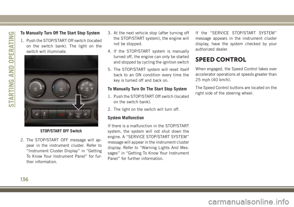
To Manually Turn Off The Start Stop System
1. Push the STOP/START Off switch (located
on the switch bank). The light on the
switch will illuminate.
2. The STOP/START OFF message will ap-
pear in the instrument cluster. Refer to
“Instrument Cluster Display” in “Getting
To Know Your Instrument Panel” for fur-
ther information.3. At the next vehicle stop (after turning off
the STOP/START system), the engine will
not be stopped.
4. If the STOP/START system is manually
turned off, the engine can only be started
and stopped by cycling the ignition switch
5. The STOP/START system will reset itself
back to an ON condition every time the
key is turned off and back on.
To Manually Turn On The Start Stop System
1. Push the STOP/START Off switch (located
on the switch bank).
2. The light on the switch will turn off.
System Malfunction
If there is a malfunction in the STOP/START
system, the system will not shut down the
engine. A “SERVICE STOP/START SYSTEM”
message will appear in the instrument cluster
display. Refer to “Warning Lights And Mes-
sages” in “Getting To Know Your Instrument
Panel” for further information.If the “SERVICE STOP/START SYSTEM”
message appears in the instrument cluster
display, have the system checked by your
authorized dealer.
SPEED CONTROL
When engaged, the Speed Control takes over
accelerator operations at speeds greater than
25 mph (40 km/h).
The Speed Control buttons are located on the
right side of the steering wheel.
STOP/START OFF Switch
STARTING AND OPERATING
136
Page 149 of 276
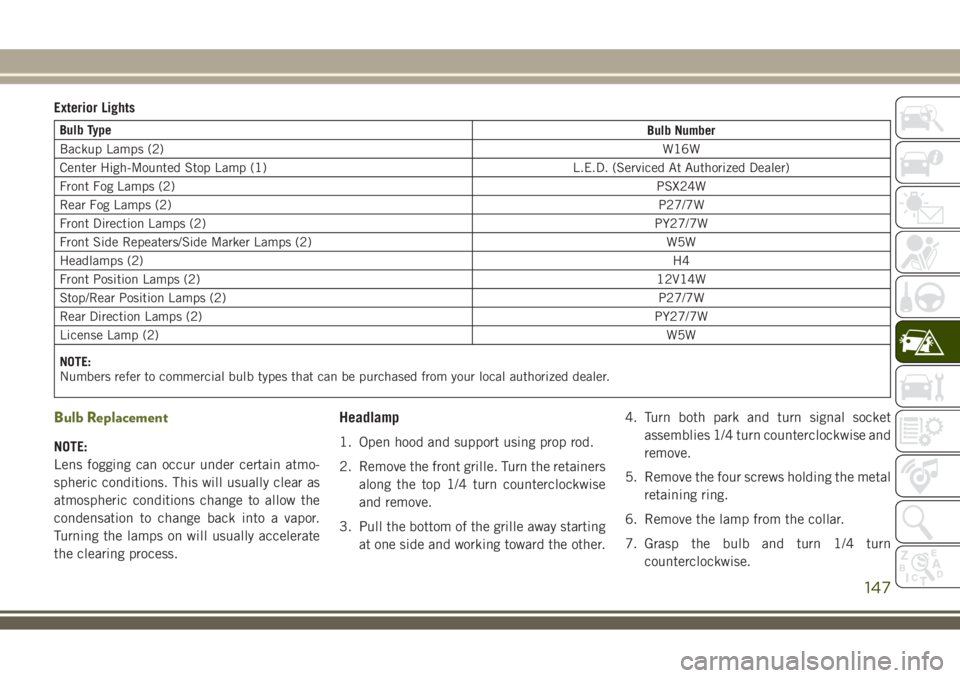
Exterior Lights
Bulb Type
Bulb Number
Backup Lamps (2)W16W
Center High-Mounted Stop Lamp (1) L.E.D. (Serviced At Authorized Dealer)
Front Fog Lamps (2)PSX24W
Rear Fog Lamps (2)P27/7W
Front Direction Lamps (2)PY27/7W
Front Side Repeaters/Side Marker Lamps (2) W5W
Headlamps (2)H4
Front Position Lamps (2)12V14W
Stop/Rear Position Lamps (2)P27/7W
Rear Direction Lamps (2)PY27/7W
License Lamp (2)W5W
NOTE:
Numbers refer to commercial bulb types that can be purchased from your local authorized dealer.
Bulb Replacement
NOTE:
Lens fogging can occur under certain atmo-
spheric conditions. This will usually clear as
atmospheric conditions change to allow the
condensation to change back into a vapor.
Turning the lamps on will usually accelerate
the clearing process.
Headlamp
1. Open hood and support using prop rod.
2. Remove the front grille. Turn the retainers
along the top 1/4 turn counterclockwise
and remove.
3. Pull the bottom of the grille away starting
at one side and working toward the other.4. Turn both park and turn signal socket
assemblies 1/4 turn counterclockwise and
remove.
5. Remove the four screws holding the metal
retaining ring.
6. Remove the lamp from the collar.
7. Grasp the bulb and turn 1/4 turn
counterclockwise.
147
Page 151 of 276
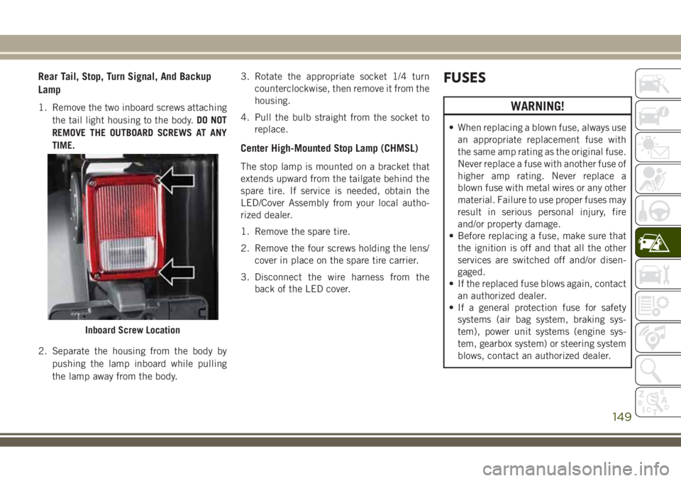
Rear Tail, Stop, Turn Signal, And Backup
Lamp
1. Remove the two inboard screws attaching
the tail light housing to the body.DO NOT
REMOVE THE OUTBOARD SCREWS AT ANY
TIME.
2. Separate the housing from the body by
pushing the lamp inboard while pulling
the lamp away from the body.3. Rotate the appropriate socket 1/4 turn
counterclockwise, then remove it from the
housing.
4. Pull the bulb straight from the socket to
replace.
Center High-Mounted Stop Lamp (CHMSL)
The stop lamp is mounted on a bracket that
extends upward from the tailgate behind the
spare tire. If service is needed, obtain the
LED/Cover Assembly from your local autho-
rized dealer.
1. Remove the spare tire.
2. Remove the four screws holding the lens/
cover in place on the spare tire carrier.
3. Disconnect the wire harness from the
back of the LED cover.
FUSES
WARNING!
• When replacing a blown fuse, always use
an appropriate replacement fuse with
the same amp rating as the original fuse.
Never replace a fuse with another fuse of
higher amp rating. Never replace a
blown fuse with metal wires or any other
material. Failure to use proper fuses may
result in serious personal injury, fire
and/or property damage.
• Before replacing a fuse, make sure that
the ignition is off and that all the other
services are switched off and/or disen-
gaged.
• If the replaced fuse blows again, contact
an authorized dealer.
• If a general protection fuse for safety
systems (air bag system, braking sys-
tem), power unit systems (engine sys-
tem, gearbox system) or steering system
blows, contact an authorized dealer.
Inboard Screw Location
149
Page 156 of 276
JACKING AND TIRE
CHANGING
WARNING!
• Do not attempt to change a tire on the
side of the vehicle close to moving traf-
fic. Pull far enough off the road to avoid
the danger of being hit when operating
the jack or changing the wheel.
• Being under a jacked-up vehicle is dan-
gerous. The vehicle could slip off the
jack and fall on you. You could be
crushed. Never put any part of your body
under a vehicle that is on a jack. If you
need to get under a raised vehicle, take
it to a service center where it can be
raised on a lift.
• Never start or run the engine while the
vehicle is on a jack.
• The jack is designed to be used as a tool
for changing tires only. The jack should
not be used to lift the vehicle for service
purposes. The vehicle should be jacked
on a firm level surface only. Avoid ice or
slippery areas.
Jack/Spare Tire Stowage
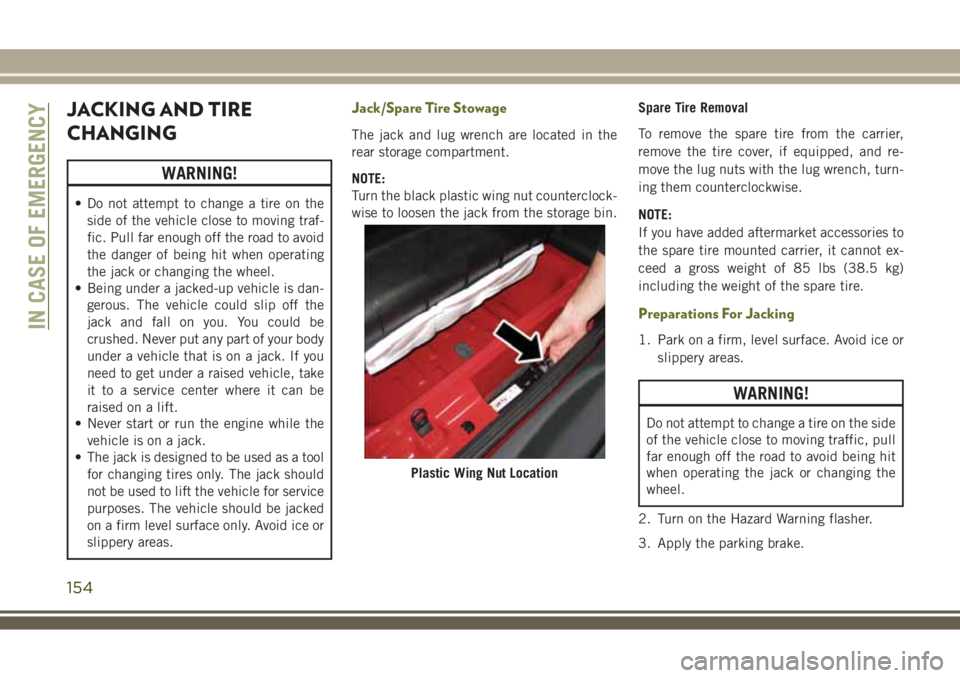
The jack and lug wrench are located in the
rear storage compartment.
NOTE:
Turn the black plastic wing nut counterclock-
wise to loosen the jack from the storage bin.Spare Tire Removal
To remove the spare tire from the carrier,
remove the tire cover, if equipped, and re-
move the lug nuts with the lug wrench, turn-
ing them counterclockwise.
NOTE:
If you have added aftermarket accessories to
the spare tire mounted carrier, it cannot ex-
ceed a gross weight of 85 lbs (38.5 kg)
including the weight of the spare tire.
Preparations For Jacking
1. Park on a firm, level surface. Avoid ice or
slippery areas.
WARNING!
Do not attempt to change a tire on the side
of the vehicle close to moving traffic, pull
far enough off the road to avoid being hit
when operating the jack or changing the
wheel.
2. Turn on the Hazard Warning flasher.
3. Apply the parking brake.
Plastic Wing Nut Location
IN CASE OF EMERGENCY
154
Page 157 of 276
4. Shift the automatic transmission into
PARK, or a manual transmission into
REVERSE.
5. Turn the ignition to LOCK.
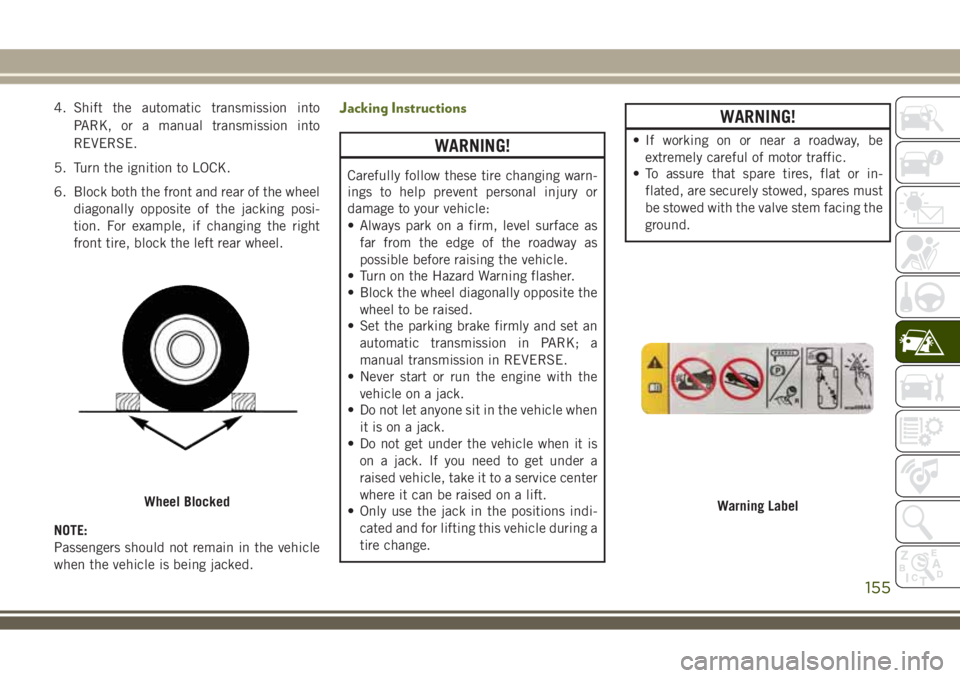
6. Block both the front and rear of the wheel
diagonally opposite of the jacking posi-
tion. For example, if changing the right
front tire, block the left rear wheel.
NOTE:
Passengers should not remain in the vehicle
when the vehicle is being jacked.Jacking Instructions
WARNING!
Carefully follow these tire changing warn-
ings to help prevent personal injury or
damage to your vehicle:
• Always park on a firm, level surface as
far from the edge of the roadway as
possible before raising the vehicle.
• Turn on the Hazard Warning flasher.
• Block the wheel diagonally opposite the
wheel to be raised.
• Set the parking brake firmly and set an
automatic transmission in PARK; a
manual transmission in REVERSE.
• Never start or run the engine with the
vehicle on a jack.
• Do not let anyone sit in the vehicle when
it is on a jack.
• Do not get under the vehicle when it is
on a jack. If you need to get under a
raised vehicle, take it to a service center
where it can be raised on a lift.
• Only use the jack in the positions indi-
cated and for lifting this vehicle during a
tire change.
WARNING!
• If working on or near a roadway, be
extremely careful of motor traffic.
• To assure that spare tires, flat or in-
flated, are securely stowed, spares must
be stowed with the valve stem facing the
ground.
Wheel BlockedWarning Label
155