ignition JEEP WRANGLER 2020 Owner handbook (in English)
[x] Cancel search | Manufacturer: JEEP, Model Year: 2020, Model line: WRANGLER, Model: JEEP WRANGLER 2020Pages: 276, PDF Size: 4.47 MB
Page 135 of 276
To activate the system, push the bottom of
the AXLE LOCK switch once to lock the rear
axle only (the “Rear Axle Lock Indicator
Light” will illuminate), push the bottom of
the switch again to lock the front axle (the
“Front Axle Lock Indicator Light” will illumi-
nate). When the rear axle is locked, pushing
the bottom of switch again will lock or unlock
the front axle.
NOTE:
The indicator lights will flash until the axles
are fully locked or unlocked.
To unlock the axles, push the top of the AXLE
LOCK switch.
Axle lock will disengage if the vehicle is taken
out of 4L (Low) range, or the ignition switch is
turned to the OFF position.
Electronic Sway Bar Disconnect — If
Equipped
Your vehicle may be equipped with an elec-
tronic disconnecting stabilizer/sway bar. This
system allows greater front suspension travel
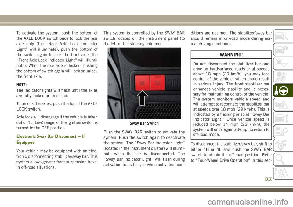
in off-road situations.This system is controlled by the SWAY BAR
switch located on the instrument panel (to
the left of the steering column).
Push the SWAY BAR switch to activate the
system. Push the switch again to deactivate
the system. The “Sway Bar Indicator Light”
(located in the instrument cluster) will illumi-
nate when the bar is disconnected. The
“Sway Bar Indicator Light” will flash during
activation transition, or when activation con-ditions are not met. The stabilizer/sway bar
should remain in on-road mode during nor-
mal driving conditions.
WARNING!
Do not disconnect the stabilizer bar and
drive on hardsurfaced roads or at speeds
above 18 mph (29 km/h); you may lose
control of the vehicle, which could result
in serious injury. The front stabilizer bar
enhances vehicle stability and is neces-
sary for maintaining control of the vehicle.
The system monitors vehicle speed and
will attempt to reconnect the stabilizer bar
at speeds over 18 mph (29 km/h). This is
indicated by a flashing or solid “Sway Bar
Indicator Light.” Once vehicle speed is
reduced below 14 mph (22 km/h), the
system will once again attempt to return to
off-road mode.
To disconnect the stabilizer/sway bar, shift to
either 4H or 4L and push the SWAY BAR
switch to obtain the off-road position. Refer
to “Four-Wheel Drive Operation” in this sec-
Sway Bar Switch
133
Page 137 of 276
Possible Reasons The Engine Does Not
AUTO STOP
Prior to engine shut down, the system will
check many safety and comfort conditions to
see if they are fulfilled. In following situations
the engine will not stop:
• Driver’s seat belt is not buckled.
• Outside temperature is less than 1°F
(–17°C) or greater than 104°F (40°C).
• Actual cabin temperature is significantly
different than temperature set on Auto
HVAC.
• HVAC is set to full defrost mode.
• Engine has not reached normal operating
temperature.
• Battery discharged.
• When driving in REVERSE.
• Hood is open.
• Vehicle is in 4LO transfer case mode.It may be possible for the vehicle to be driven
several times without the STOP/START sys-
tem going into a STOP/START READY state
under more extreme conditions of the items
listed above.
To Start The Engine While In The STOP/
START AUTO STOP ACTIVE Mode
When the gear selector is in NEUTRAL, the
engine will start when the clutch pedal is
pressed. The vehicle will go into STOP/START
SYSTEM NOT READY mode until the vehicle
speed is greater than 3 mph (5 km/h).
Conditions that will cause the engine to start
automatically while in STOP/START AUTO STOP
ACTIVE mode
The Engine Will Start Automatically When:
• Actual cabin temperature is significantly
different than temperature set on Auto
HVAC.
• HVAC is set to full defrost mode.
• STOP/START AUTO STOP ACTIVE time ex-
ceeds 5 minutes.• Battery voltage drops too low.
• Low brake vacuum e.g. after several brake
pedal applications.
•
Vehicle is moving faster than 3 mph (5 km/h).
• STOP/START OFF switch is pressed.
• 4WD system is put into 4LO mode.
Conditions that force a manual key cycle
start while in STOP/START AUTO STOP AC-
TIVE mode:
The Engine Will Not Start Automatically If:
• The driver’s seatbelt was unbuckled
• The engine hood has been opened
• A STOP/START system error occurs
The engine may then only be restarted with
an ignition key cycle. The STOP/START KEY
START REQUIRED message will appear in
the instrument cluster under these condi-
tions. Refer to “Instrument Cluster Display”
in “Getting To Know Your Instrument Panel”
for further information.
135
Page 138 of 276
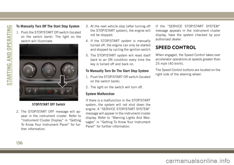
To Manually Turn Off The Start Stop System
1. Push the STOP/START Off switch (located
on the switch bank). The light on the
switch will illuminate.
2. The STOP/START OFF message will ap-
pear in the instrument cluster. Refer to
“Instrument Cluster Display” in “Getting
To Know Your Instrument Panel” for fur-
ther information.3. At the next vehicle stop (after turning off
the STOP/START system), the engine will
not be stopped.
4. If the STOP/START system is manually
turned off, the engine can only be started
and stopped by cycling the ignition switch
5. The STOP/START system will reset itself
back to an ON condition every time the
key is turned off and back on.
To Manually Turn On The Start Stop System
1. Push the STOP/START Off switch (located
on the switch bank).
2. The light on the switch will turn off.
System Malfunction
If there is a malfunction in the STOP/START
system, the system will not shut down the
engine. A “SERVICE STOP/START SYSTEM”
message will appear in the instrument cluster
display. Refer to “Warning Lights And Mes-
sages” in “Getting To Know Your Instrument
Panel” for further information.If the “SERVICE STOP/START SYSTEM”
message appears in the instrument cluster
display, have the system checked by your
authorized dealer.
SPEED CONTROL
When engaged, the Speed Control takes over
accelerator operations at speeds greater than
25 mph (40 km/h).
The Speed Control buttons are located on the
right side of the steering wheel.
STOP/START OFF Switch
STARTING AND OPERATING
136
Page 140 of 276
The driver’s preferred units can be selected
through the instrument panel settings if
equipped. Refer to “Getting To Know Your
Instrument Panel” in the Owner’s Manual for
more information. The speed increment
shown is dependent on the chosen speed unit
of U.S. (mph) or Metric (km/h):
U.S. Speed (mph)
• Pushing the RES (+) button once will result
in a 1 mph increase in set speed. Each
subsequent tap of the button results in an
increase of 1 mph.
• If the button is continually pushed, the set
speed will continue to increase until the
button is released, then the new set speed
will be established.
Metric Speed (km/h)
• Pushing the RES (+) button once will result
in a 1 km/h increase in set speed. Each
subsequent tap of the button results in an
increase of 1 km/h.
• If the button is continually pushed, the set
speed will continue to increase until the
button is released, then the new set speed
will be established.To Decrease Speed
When the Speed Control is set, you can de-
crease speed by pushing the SET (-) button.
The driver’s preferred units can be selected
through the instrument panel settings if
equipped. Refer to “Getting To Know Your
Instrument Panel” in the Owner’s Manual for
more information. The speed increment
shown is dependent on the chosen speed unit
of U.S. (mph) or Metric (km/h):
U.S. Speed (mph)
• Pushing the SET (-) button once will result
in a 1 mph decrease in set speed. Each
subsequent tap of the button results in a
decrease of 1 mph.
• If the button is continually pushed, the set
speed will continue to decrease until the
button is released, then the new set speed
will be established.
Metric Speed (km/h)
• Pushing the SET (-) button once will result
in a 1 km/h decrease in set speed. Each
subsequent tap of the button results in a
decrease of 1 km/h.• If the button is continually pushed, the set
speed will continue to decrease until the
button is released, then the new set speed
will be established.
To Accelerate For Passing
Press the accelerator as you would normally.
When the pedal is released, the vehicle will
return to the set speed.
To Resume Speed
To resume a previously set speed, push the
RES (+) button and release. Resume can be
used at any speed above 20 mph (32 km/h).
To Deactivate
A soft tap on the brake pedal, pushing the
CANCEL button, or normal brake pressure
while slowing the vehicle will deactivate the
Speed Control without erasing the set speed
from memory.
Pushing the ON/OFF button or turning the
ignition switch OFF erases the set speed from
memory.
STARTING AND OPERATING
138
Page 144 of 276
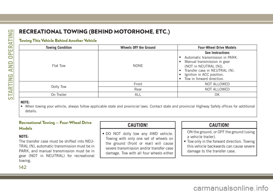
RECREATIONAL TOWING (BEHIND MOTORHOME, ETC.)
Towing This Vehicle Behind Another Vehicle
Towing Condition Wheels OFF the Ground Four-Wheel Drive Models
Flat Tow NONESee Instructions
•
Automatic transmission in PARK.
• Manual transmission in gear
(NOT in NEUTRAL [N]).
• Transfer case in NEUTRAL (N).
• Ignition in ACC position.
• Tow in forward direction.
Dolly TowFront NOT ALLOWED
Rear NOT ALLOWED
On Trailer ALL OK
NOTE:
• When towing your vehicle, always follow applicable state and provincial laws. Contact state and provincial Highway Safety offices for additional
details.
Recreational Towing — Four-Wheel Drive
Models
NOTE:
The transfer case must be shifted into NEU-
TRAL (N), automatic transmission must be in
PARK, and manual transmission must be in
gear (NOT in NEUTRAL) for recreational
towing.
CAUTION!
• DO NOT dolly tow any 4WD vehicle.
Towing with only one set of wheels on
the ground (front or rear) will cause
severe transmission and/or transfer case
damage. Tow with all four wheels either
CAUTION!
ON the ground, or OFF the ground (using
a vehicle trailer).
• Tow only in the forward direction. Towing
this vehicle backwards can cause severe
damage to the transfer case.
STARTING AND OPERATING
142
Page 146 of 276
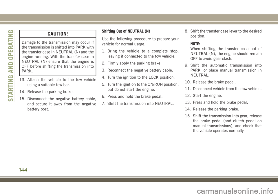
CAUTION!
Damage to the transmission may occur if
the transmission is shifted into PARK with
the transfer case in NEUTRAL (N) and the
engine running. With the transfer case in
NEUTRAL (N) ensure that the engine is
OFF before shifting the transmission into
PARK.
13. Attach the vehicle to the tow vehicle
using a suitable tow bar.
14. Release the parking brake.
15. Disconnect the negative battery cable,
and secure it away from the negative
battery post.
Shifting Out of NEUTRAL (N)
Use the following procedure to prepare your
vehicle for normal usage.
1. Bring the vehicle to a complete stop,
leaving it connected to the tow vehicle.
2. Firmly apply the parking brake.
3. Reconnect the negative battery cable.
4. Turn the ignition to the LOCK position.
5. Turn the ignition to the ON/RUN position,
but do not start the engine.
6. Press and hold the brake pedal.
7. Shift the transmission into NEUTRAL.8. Shift the transfer case lever to the desired
position.
NOTE:
When shifting the transfer case out of
NEUTRAL (N), the engine should remain
OFF to avoid gear clash.
9. Shift the automatic transmission into
PARK, or place manual transmission in
NEUTRAL.
10. Release the brake pedal.
11. Disconnect vehicle from the tow vehicle.
12. Start the engine.
13. Press and hold the brake pedal.
14. Release the parking brake.
15. Shift the transmission into gear, release
the brake pedal (and clutch pedal on
manual transmissions), and check that
the vehicle operates normally.
STARTING AND OPERATING
144
Page 147 of 276
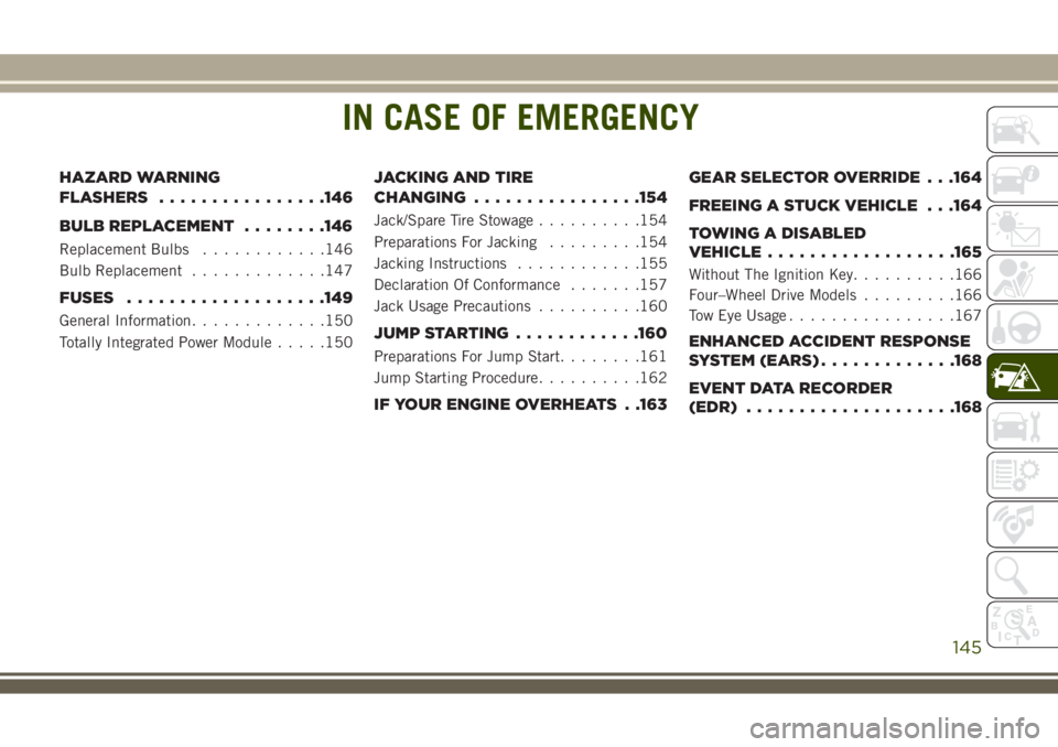
IN CASE OF EMERGENCY
HAZARD WARNING
FLASHERS................146
BULB REPLACEMENT........146
Replacement Bulbs............146
Bulb Replacement.............147
FUSES...................149
General Information.............150
Totally Integrated Power Module.....150
JACKING AND TIRE
CHANGING................154
Jack/Spare Tire Stowage..........154
Preparations For Jacking.........154
Jacking Instructions............155
Declaration Of Conformance.......157
Jack Usage Precautions..........160
JUMP STARTING............160
Preparations For Jump Start........161
Jump Starting Procedure..........162
IF YOUR ENGINE OVERHEATS . .163GEAR SELECTOR OVERRIDE . . .164
FREEING A STUCK VEHICLE . . .164
TOWING A DISABLED
VEHICLE..................165
Without The Ignition Key..........166
Four–Wheel Drive Models.........166
Tow Eye Usage................167
ENHANCED ACCIDENT RESPONSE
SYSTEM (EARS).............168
EVENT DATA RECORDER
(EDR)....................168
IN CASE OF EMERGENCY
145
Page 148 of 276
HAZARD WARNING
FLASHERS
The Hazard Warning flasher switch is located
on the instrument panel below the climate
controls.
Push the switch to turn on the
Hazard Warning flasher. When the
switch is activated, all directionalturn signals will flash on and off to warn
oncoming traffic of an emergency. Push the
switch a second time to turn off the Hazard
Warning flashers.
This is an emergency warning system and it
should not be used when the vehicle is in
motion. Use it when your vehicle is disabled
and it is creating a safety hazard for other
motorists.When you must leave the vehicle to seek
assistance, the Hazard Warning flashers will
continue to operate even though the ignition
is placed in the OFF position.
NOTE:
With extended use the Hazard Warning flash-
ers may wear down your battery.
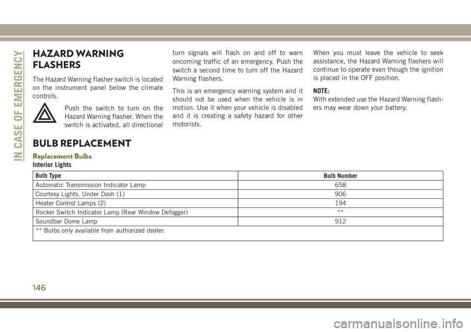
BULB REPLACEMENT
Replacement Bulbs
Interior Lights
Bulb Type
Bulb Number
Automatic Transmission Indicator Lamp 658
Courtesy Lights, Under Dash (1)906
Heater Control Lamps (2)194
Rocker Switch Indicator Lamp (Rear Window Defogger) **
Soundbar Dome Lamp912
** Bulbs only available from authorized dealer.
IN CASE OF EMERGENCY
146
Page 151 of 276
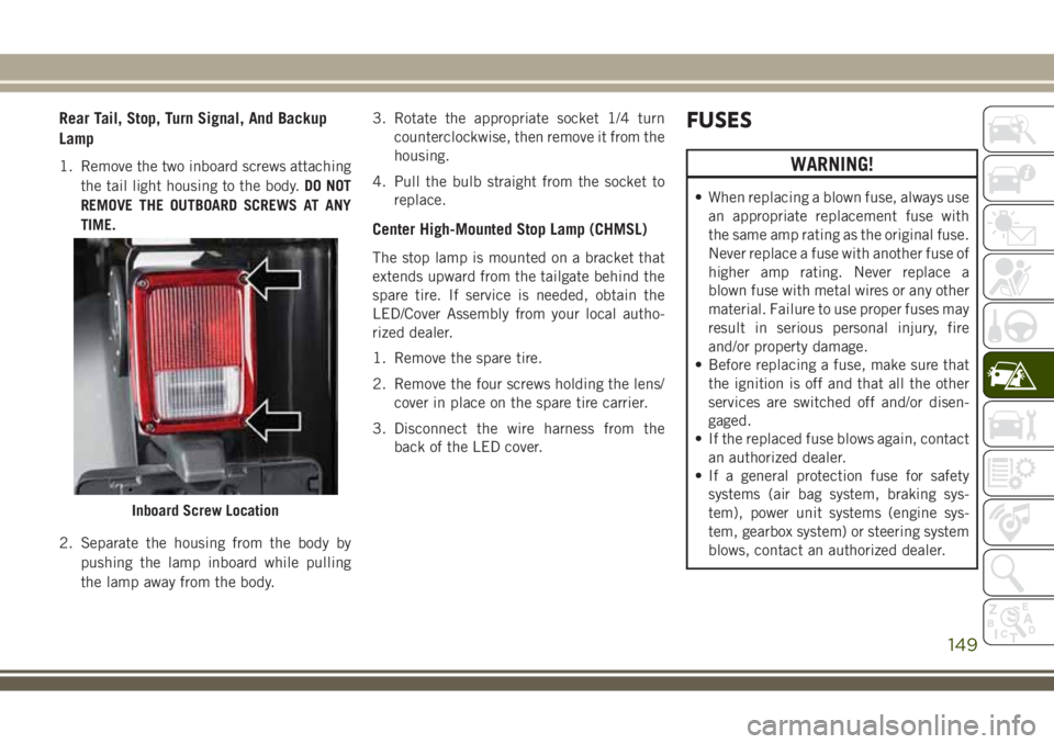
Rear Tail, Stop, Turn Signal, And Backup
Lamp
1. Remove the two inboard screws attaching
the tail light housing to the body.DO NOT
REMOVE THE OUTBOARD SCREWS AT ANY
TIME.
2. Separate the housing from the body by
pushing the lamp inboard while pulling
the lamp away from the body.3. Rotate the appropriate socket 1/4 turn
counterclockwise, then remove it from the
housing.
4. Pull the bulb straight from the socket to
replace.
Center High-Mounted Stop Lamp (CHMSL)
The stop lamp is mounted on a bracket that
extends upward from the tailgate behind the
spare tire. If service is needed, obtain the
LED/Cover Assembly from your local autho-
rized dealer.
1. Remove the spare tire.
2. Remove the four screws holding the lens/
cover in place on the spare tire carrier.
3. Disconnect the wire harness from the
back of the LED cover.
FUSES
WARNING!
• When replacing a blown fuse, always use
an appropriate replacement fuse with
the same amp rating as the original fuse.
Never replace a fuse with another fuse of
higher amp rating. Never replace a
blown fuse with metal wires or any other
material. Failure to use proper fuses may
result in serious personal injury, fire
and/or property damage.
• Before replacing a fuse, make sure that
the ignition is off and that all the other
services are switched off and/or disen-
gaged.
• If the replaced fuse blows again, contact
an authorized dealer.
• If a general protection fuse for safety
systems (air bag system, braking sys-
tem), power unit systems (engine sys-
tem, gearbox system) or steering system
blows, contact an authorized dealer.
Inboard Screw Location
149
Page 153 of 276
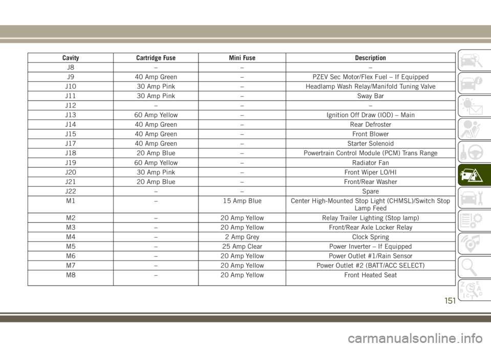
Cavity Cartridge Fuse Mini Fuse Description
J8 – – –
J9 40 Amp Green – PZEV Sec Motor/Flex Fuel – If Equipped
J10 30 Amp Pink – Headlamp Wash Relay/Manifold Tuning Valve
J11 30 Amp Pink – Sway Bar
J12 – – –
J13 60 Amp Yellow – Ignition Off Draw (IOD) – Main
J14 40 Amp Green – Rear Defroster
J15 40 Amp Green – Front Blower
J17 40 Amp Green – Starter Solenoid
J18 20 Amp Blue – Powertrain Control Module (PCM) Trans Range
J19 60 Amp Yellow – Radiator Fan
J20 30 Amp Pink – Front Wiper LO/HI
J21 20 Amp Blue – Front/Rear Washer
J22 – – Spare
M1 – 15 Amp Blue Center High-Mounted Stop Light (CHMSL)/Switch Stop
Lamp Feed
M2 – 20 Amp Yellow Relay Trailer Lighting (Stop lamp)
M3 – 20 Amp Yellow Front/Rear Axle Locker Relay
M4 – 2 Amp Grey Clock Spring
M5 – 25 Amp Clear Power Inverter – If Equipped
M6 – 20 Amp Yellow Power Outlet #1/Rain Sensor
M7 – 20 Amp Yellow Power Outlet #2 (BATT/ACC SELECT)
M8 – 20 Amp Yellow Front Heated Seat
151