lock JEEP WRANGLER 2021 Owner handbook (in English)
[x] Cancel search | Manufacturer: JEEP, Model Year: 2021, Model line: WRANGLER, Model: JEEP WRANGLER 2021Pages: 276, PDF Size: 4.47 MB
Page 61 of 276
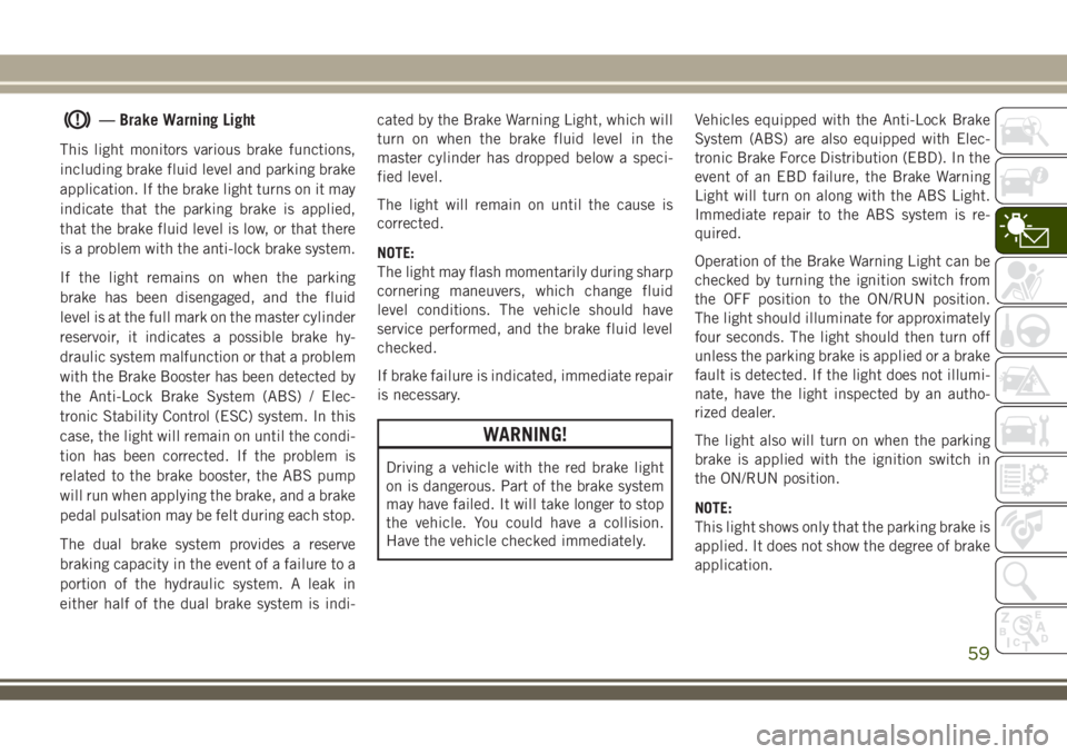
— Brake Warning Light
This light monitors various brake functions,
including brake fluid level and parking brake
application. If the brake light turns on it may
indicate that the parking brake is applied,
that the brake fluid level is low, or that there
is a problem with the anti-lock brake system.
If the light remains on when the parking
brake has been disengaged, and the fluid
level is at the full mark on the master cylinder
reservoir, it indicates a possible brake hy-
draulic system malfunction or that a problem
with the Brake Booster has been detected by
the Anti-Lock Brake System (ABS) / Elec-
tronic Stability Control (ESC) system. In this
case, the light will remain on until the condi-
tion has been corrected. If the problem is
related to the brake booster, the ABS pump
will run when applying the brake, and a brake
pedal pulsation may be felt during each stop.
The dual brake system provides a reserve
braking capacity in the event of a failure to a
portion of the hydraulic system. A leak in
either half of the dual brake system is indi-cated by the Brake Warning Light, which will
turn on when the brake fluid level in the
master cylinder has dropped below a speci-
fied level.
The light will remain on until the cause is
corrected.
NOTE:
The light may flash momentarily during sharp
cornering maneuvers, which change fluid
level conditions. The vehicle should have
service performed, and the brake fluid level
checked.
If brake failure is indicated, immediate repair
is necessary.
WARNING!
Driving a vehicle with the red brake light
on is dangerous. Part of the brake system
may have failed. It will take longer to stop
the vehicle. You could have a collision.
Have the vehicle checked immediately.Vehicles equipped with the Anti-Lock Brake
System (ABS) are also equipped with Elec-
tronic Brake Force Distribution (EBD). In the
event of an EBD failure, the Brake Warning
Light will turn on along with the ABS Light.
Immediate repair to the ABS system is re-
quired.
Operation of the Brake Warning Light can be
checked by turning the ignition switch from
the OFF position to the ON/RUN position.
The light should illuminate for approximately
four seconds. The light should then turn off
unless the parking brake is applied or a brake
fault is detected. If the light does not illumi-
nate, have the light inspected by an autho-
rized dealer.
The light also will turn on when the parking
brake is applied with the ignition switch in
the ON/RUN position.
NOTE:
This light shows only that the parking brake is
applied. It does not show the degree of brake
application.
59
Page 63 of 276
remain on continuously and a chime will
sound. Refer to “Occupant Restraints Sys-
tems” in “Safety” for further information.
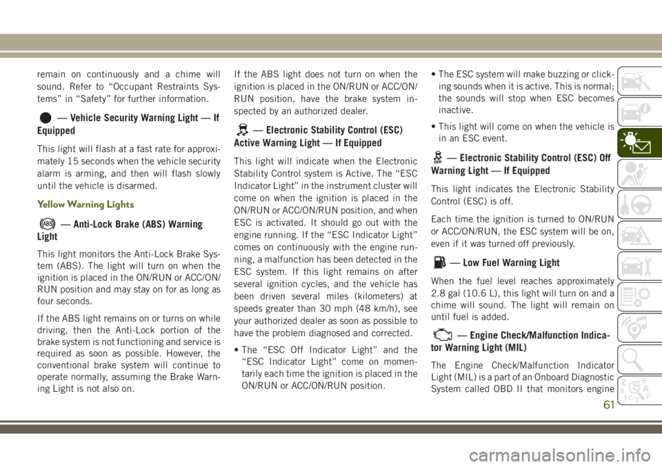
— Vehicle Security Warning Light — If
Equipped
This light will flash at a fast rate for approxi-
mately 15 seconds when the vehicle security
alarm is arming, and then will flash slowly
until the vehicle is disarmed.
Yellow Warning Lights
— Anti-Lock Brake (ABS) Warning
Light
This light monitors the Anti-Lock Brake Sys-
tem (ABS). The light will turn on when the
ignition is placed in the ON/RUN or ACC/ON/
RUN position and may stay on for as long as
four seconds.
If the ABS light remains on or turns on while
driving, then the Anti-Lock portion of the
brake system is not functioning and service is
required as soon as possible. However, the
conventional brake system will continue to
operate normally, assuming the Brake Warn-
ing Light is not also on.If the ABS light does not turn on when the
ignition is placed in the ON/RUN or ACC/ON/
RUN position, have the brake system in-
spected by an authorized dealer.
— Electronic Stability Control (ESC)
Active Warning Light — If Equipped
This light will indicate when the Electronic
Stability Control system is Active. The “ESC
Indicator Light” in the instrument cluster will
come on when the ignition is placed in the
ON/RUN or ACC/ON/RUN position, and when
ESC is activated. It should go out with the
engine running. If the “ESC Indicator Light”
comes on continuously with the engine run-
ning, a malfunction has been detected in the
ESC system. If this light remains on after
several ignition cycles, and the vehicle has
been driven several miles (kilometers) at
speeds greater than 30 mph (48 km/h), see
your authorized dealer as soon as possible to
have the problem diagnosed and corrected.
• The “ESC Off Indicator Light” and the
“ESC Indicator Light” come on momen-
tarily each time the ignition is placed in the
ON/RUN or ACC/ON/RUN position.• The ESC system will make buzzing or click-
ing sounds when it is active. This is normal;
the sounds will stop when ESC becomes
inactive.
• This light will come on when the vehicle is
in an ESC event.— Electronic Stability Control (ESC) Off
Warning Light — If Equipped
This light indicates the Electronic Stability
Control (ESC) is off.
Each time the ignition is turned to ON/RUN
or ACC/ON/RUN, the ESC system will be on,
even if it was turned off previously.
— Low Fuel Warning Light
When the fuel level reaches approximately
2.8 gal (10.6 L), this light will turn on and a
chime will sound. The light will remain on
until fuel is added.
— Engine Check/Malfunction Indica-
tor Warning Light (MIL)
The Engine Check/Malfunction Indicator
Light (MIL) is a part of an Onboard Diagnostic
System called OBD II that monitors engine
61
Page 65 of 276
As an added safety feature, your vehicle has
been equipped with a tire pressure monitor-
ing system (TPMS) that illuminates a low tire
pressure telltale when one or more of your
tires is significantly under-inflated. Accord-
ingly, when the low tire pressure telltale illu-
minates, you should stop and check your tires
as soon as possible, and inflate them to the
proper pressure. Driving on a significantly
under-inflated tire causes the tire to overheat
and can lead to tire failure. Under-inflation
also reduces fuel efficiency and tire tread
life, and may affect the vehicle’s handling
and stopping ability.
Please note that the TPMS is not a substitute
for proper tire maintenance, and it is the
driver’s responsibility to maintain correct tire
pressure, even if under-inflation has not
reached the level to trigger illumination of the
TPMS low tire pressure telltale.
Your vehicle has also been equipped with a
TPMS malfunction indicator to indicate when
the system is not operating properly. The
TPMS malfunction indicator is combined
with the low tire pressure telltale. When the
system detects a malfunction, the telltale willflash for approximately one minute and then
remain continuously illuminated. This se-
quence will continue upon subsequent ve-
hicle start-ups as long as the malfunction
exists. When the malfunction indicator is
illuminated, the system may not be able to
detect or signal low tire pressure as intended.
TPMS malfunctions may occur for a variety of
reasons, including the installation of replace-
ment or alternate tires or wheels on the ve-
hicle that prevent the TPMS from functioning
properly. Always check the TPMS malfunc-
tion telltale after replacing one or more tires
or wheels on your vehicle to ensure that the
replacement or alternate tires and wheels
allow the TPMS to continue to function
properly.
CAUTION!
The TPMS has been optimized for the
original equipment tires and wheels.
TPMS pressures and warning have been
established for the tire size equipped on
your vehicle. Undesirable system opera-
tion or sensor damage may result when
using replacement equipment that is not
CAUTION!
of the same size, type, and/or style. After-
market wheels can cause sensor damage.
Using aftermarket tire sealants may cause
the Tire Pressure Monitoring System
(TPMS) sensor to become inoperable. Af-
ter using an aftermarket tire sealant it is
recommended that you take your vehicle to
your authorized dealer to have your sensor
function checked.
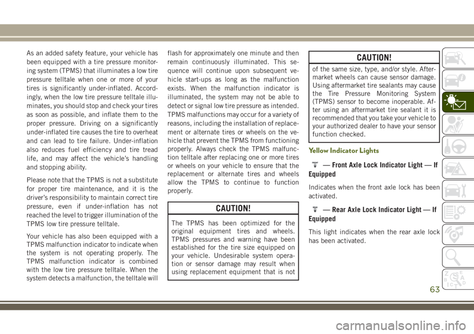
Yellow Indicator Lights
— Front Axle Lock Indicator Light — If
Equipped
Indicates when the front axle lock has been
activated.
— Rear Axle Lock Indicator Light — If
Equipped
This light indicates when the rear axle lock
has been activated.
63
Page 66 of 276
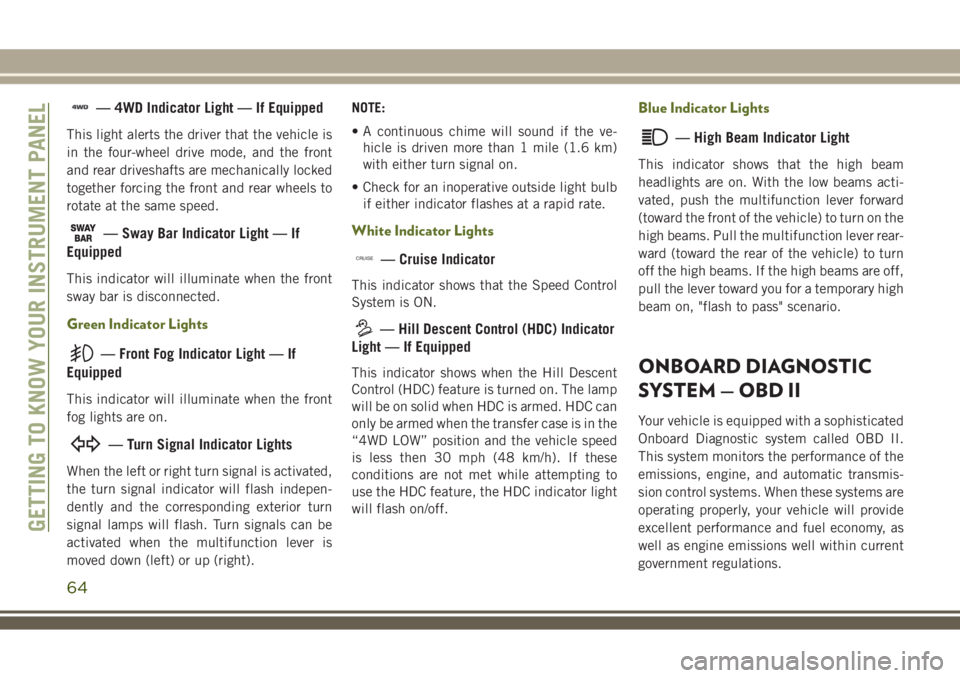
— 4WD Indicator Light — If Equipped
This light alerts the driver that the vehicle is
in the four-wheel drive mode, and the front
and rear driveshafts are mechanically locked
together forcing the front and rear wheels to
rotate at the same speed.
— Sway Bar Indicator Light — If
Equipped
This indicator will illuminate when the front
sway bar is disconnected.
Green Indicator Lights
— Front Fog Indicator Light — If
Equipped
This indicator will illuminate when the front
fog lights are on.
— Turn Signal Indicator Lights
When the left or right turn signal is activated,
the turn signal indicator will flash indepen-
dently and the corresponding exterior turn
signal lamps will flash. Turn signals can be
activated when the multifunction lever is
moved down (left) or up (right).NOTE:
• A continuous chime will sound if the ve-
hicle is driven more than 1 mile (1.6 km)
with either turn signal on.
• Check for an inoperative outside light bulb
if either indicator flashes at a rapid rate.
White Indicator Lights
CRUISE— Cruise Indicator
This indicator shows that the Speed Control
System is ON.
— Hill Descent Control (HDC) Indicator
Light — If Equipped
This indicator shows when the Hill Descent
Control (HDC) feature is turned on. The lamp
will be on solid when HDC is armed. HDC can
only be armed when the transfer case is in the
“4WD LOW” position and the vehicle speed
is less then 30 mph (48 km/h). If these
conditions are not met while attempting to
use the HDC feature, the HDC indicator light
will flash on/off.
Blue Indicator Lights
— High Beam Indicator Light
This indicator shows that the high beam
headlights are on. With the low beams acti-
vated, push the multifunction lever forward
(toward the front of the vehicle) to turn on the
high beams. Pull the multifunction lever rear-
ward (toward the rear of the vehicle) to turn
off the high beams. If the high beams are off,
pull the lever toward you for a temporary high
beam on, "flash to pass" scenario.
ONBOARD DIAGNOSTIC
SYSTEM — OBD II
Your vehicle is equipped with a sophisticated
Onboard Diagnostic system called OBD II.
This system monitors the performance of the
emissions, engine, and automatic transmis-
sion control systems. When these systems are
operating properly, your vehicle will provide
excellent performance and fuel economy, as
well as engine emissions well within current
government regulations.
GETTING TO KNOW YOUR INSTRUMENT PANEL
64
Page 69 of 276
SAFETY
SAFETY FEATURES...........68
Anti-Lock Brake System (ABS)......68
Electronic Brake Control System.....69
AUXILIARY DRIVING SYSTEMS . .77
Tire Pressure Monitor System (TPMS) . .77
OCCUPANT RESTRAINT
SYSTEMS..................84
Occupant Restraint Systems........84
Important Safety Precautions.......84
Seat Belt Systems..............85
Supplemental Restraint Systems (SRS). .92
Child Restraints — Carrying Children
Safely......................99
Transporting Pets..............112
SAFETY TIPS...............112
Transporting Passengers..........112
Exhaust Gas.................112
Safety Checks You Should Make
Inside The Vehicle.............113
Periodic Safety Checks You Should Make
Outside The Vehicle.............114
SAFETY
67
Page 70 of 276
SAFETY FEATURES
Anti-Lock Brake System (ABS)
The Anti-Lock Brake System (ABS) provides
increased vehicle stability and brake perfor-
mance under most braking conditions. The
system automatically prevents wheel lock,
and enhances vehicle control during braking.
The ABS performs a self-check cycle to en-
sure that the ABS is working properly each
time the vehicle is started and driven. During
this self-check, you may hear a slight clicking
sound as well as some related motor noises.
ABS is activated during braking when the
system detects one or more wheels begin to
lock. Road conditions such as ice, snow,
gravel, bumps, railroad tracks, loose debris,
or panic stops may increase the likelihood of
ABS activation(s).
You also may experience the following when
ABS activates:
• The ABS motor noise (it may continue to
run for a short time after the stop).
• The clicking sound of solenoid valves.• Brake pedal pulsations.
• A slight drop of the brake pedal at the end
of the stop.
These are all normal characteristics of ABS.
WARNING!
• The ABS contains sophisticated elec-
tronic equipment that may be suscep-
tible to interference caused by improp-
erly installed or high output radio
transmitting equipment. This interfer-
ence can cause possible loss of anti-lock
braking capability. Installation of such
equipment should be performed by
qualified professionals.
• Pumping of the Anti-Lock Brakes will
diminish their effectiveness and may
lead to a collision. Pumping makes the
stopping distance longer. Just press
firmly on your brake pedal when you
need to slow down or stop.
• The ABS cannot prevent the natural laws
of physics from acting on the vehicle,
nor can it increase braking or steering
efficiency beyond that afforded by the
WARNING!
condition of the vehicle brakes and tires
or the traction afforded.
• The ABS cannot prevent collisions, in-
cluding those resulting from excessive
speed in turns, following another vehicle
too closely, or hydroplaning.
• The capabilities of an ABS equipped
vehicle must never be exploited in a
reckless or dangerous manner that could
jeopardize the user’s safety or the safety
of others.
ABS is designed to function with the OEM
tires. Modification may result in degraded
ABS performance.
Anti-Lock Brake Warning Light
The yellow “Anti-Lock Brake Warning Light”
will turn on when the ignition is turned to the
ON/RUN mode and may stay on for as long as
four seconds.
If the “Anti-Lock Brake Warning Light” re-
mains on or comes on while driving, it indi-
cates that the anti-lock portion of the brake
system is not functioning and that service is
SAFETY
68
Page 71 of 276
required. However, the conventional brake
system will continue to operate normally if
the “Brake System Warning Light” is not on.
If the “Anti-Lock Brake Warning Light” is on,
the brake system should be serviced as soon
as possible to restore the benefits of anti-lock
brakes. If the “Anti-Lock Brake Warning
Light” does not come on when the ignition is
turned to the ON/RUN mode, have the light
repaired as soon as possible.
Electronic Brake Control System
Your vehicle is equipped with an advanced
Electronic Brake Control system (EBC). This
system includes Electronic Brake Force Dis-
tribution (EBD), Brake Assist System (BAS),
Hill Start Assist (HSA), Traction Control Sys-
tem (TCS), Electronic Stability Control
(ESC), and Electronic Roll Mitigation (ERM).
These systems work together to enhance both
vehicle stability and control in various driving
conditions.
Your vehicle may also be equipped with
Trailer Sway Control (TSC) and Hill Descent
Control (HDC).
Electronic Brake Force Distribution (EBD)
This function manages the distribution of the
braking torque between the front and rear
axles by limiting braking pressure to the rear
axle. This is done to prevent overslip of the
rear wheels to avoid vehicle instability, and to
prevent the rear axle from entering ABS be-
fore the front axle.
Brake System Warning Light
The red “Brake System Warning Light” will
turn on when the ignition is turned to the
ON/RUN mode and may stay on for as long as
four seconds.
If the “Brake System Warning Light” remains
on or comes on while driving, it indicates that
the brake system is not functioning properly
and that immediate service is required. If the
“Brake System Warning Light” does not
come on when the ignition is turned to the
ON/RUN mode, have the light repaired as
soon as possible.
Brake Assist System (BAS)
The BAS is designed to optimize the vehicle’s
braking capability during emergency braking
maneuvers. The system detects an emer-
gency braking situation by sensing the rate
and amount of brake application and then
applies optimum pressure to the brakes. This
can help reduce braking distances. The BAS
complements the anti-lock brake system
(ABS). Applying the brakes very quickly re-
sults in the best BAS assistance. To receive
the benefit of the system, you must apply
continuous braking pressure during the stop-
ping sequence, (do not “pump” the brakes).
Do not reduce brake pedal pressure unless
braking is no longer desired. Once the brake
pedal is released, the BAS is deactivated.
WARNING!
The Brake Assist System (BAS) cannot
prevent the natural laws of physics from
acting on the vehicle, nor can it increase
the traction afforded by prevailing road
conditions. BAS cannot prevent collisions,
including those resulting from excessive
69
Page 88 of 276
Belt Reminder Light will remain on until the
seat belts are buckled. The BeltAlert warning
sequence may repeat based on vehicle speed
until the driver and occupied outboard front
seat passenger seat belts are buckled. The
driver should instruct all occupants to buckle
their seat belts.
Change of Status
If the driver or outboard front seat passenger
(if equipped with outboard front passenger
seat BeltAlert) unbuckles their seat belt
while the vehicle is traveling, the BeltAlert
warning sequence will begin until the seat
belts are buckled again.
The outboard front passenger seat BeltAlert
is not active when the outboard front passen-
ger seat is unoccupied. BeltAlert may be
triggered when an animal or other items are
placed on the outboard front passenger seat
or when the seat is folded flat (if equipped). It
is recommended that pets be restrained in
the rear seat (if equipped) in pet harnesses or
pet carriers that are secured by seat belts,
and cargo is properly stowed.BeltAlert can be activated or deactivated by
your authorized dealer. FCA US LLC does not
recommend deactivating BeltAlert.
NOTE:
If BeltAlert has been deactivated and the
driver or outboard front seat passenger (if
equipped with outboard front passenger seat
BeltAlert) is unbuckled the Seat Belt Re-
minder Light will turn on and remain on until
the driver and outboard front seat passenger
seat belts are buckled.
Lap/Shoulder Belts
All seating positions in your vehicle are
equipped with lap/shoulder belts.
The seat belt webbing retractor will lock only
during very sudden stops or collisions. This
feature allows the shoulder part of the seat
belt to move freely with you under normal
conditions. However, in a collision the seat
belt will lock and reduce your risk of striking
the inside of the vehicle or being thrown out
of the vehicle.
WARNING!
• Relying on the air bags alone could lead
to more severe injuries in a collision. The
air bags work with your seat belt to
restrain you properly. In some collisions,
the air bags won’t deploy at all. Always
wear your seat belt even though you have
air bags.
• In a collision, you and your passengers
can suffer much greater injuries if you
are not properly buckled up. You can
strike the interior of your vehicle or other
passengers, or you can be thrown out of
the vehicle. Always be sure you and
others in your vehicle are buckled up
properly.
• It is dangerous to ride in a cargo area,
inside or outside of a vehicle. In a colli-
sion, people riding in these areas are
more likely to be seriously injured or
killed.
• Do not allow people to ride in any area of
your vehicle that is not equipped with
seats and seat belts.
SAFETY
86
Page 90 of 276
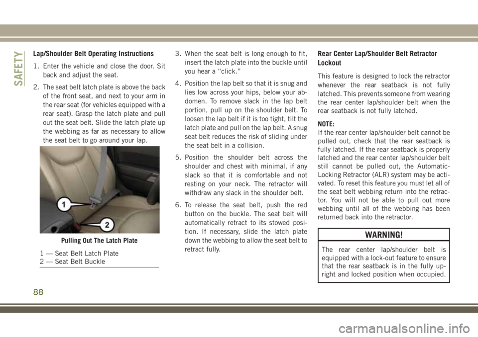
Lap/Shoulder Belt Operating Instructions
1. Enter the vehicle and close the door. Sit
back and adjust the seat.
2. The seat belt latch plate is above the back
of the front seat, and next to your arm in
the rear seat (for vehicles equipped with a
rear seat). Grasp the latch plate and pull
out the seat belt. Slide the latch plate up
the webbing as far as necessary to allow
the seat belt to go around your lap.3. When the seat belt is long enough to fit,
insert the latch plate into the buckle until
you hear a “click.”
4. Position the lap belt so that it is snug and
lies low across your hips, below your ab-
domen. To remove slack in the lap belt
portion, pull up on the shoulder belt. To
loosen the lap belt if it is too tight, tilt the
latch plate and pull on the lap belt. A snug
seat belt reduces the risk of sliding under
the seat belt in a collision.
5. Position the shoulder belt across the
shoulder and chest with minimal, if any
slack so that it is comfortable and not
resting on your neck. The retractor will
withdraw any slack in the shoulder belt.
6. To release the seat belt, push the red
button on the buckle. The seat belt will
automatically retract to its stowed posi-
tion. If necessary, slide the latch plate
down the webbing to allow the seat belt to
retract fully.
Rear Center Lap/Shoulder Belt Retractor
Lockout
This feature is designed to lock the retractor
whenever the rear seatback is not fully
latched. This prevents someone from wearing
the rear center lap/shoulder belt when the
rear seatback is not fully latched.
NOTE:
If the rear center lap/shoulder belt cannot be
pulled out, check that the rear seatback is
fully latched. If the rear seatback is properly
latched and the rear center lap/shoulder belt
still cannot be pulled out, the Automatic-
Locking Retractor (ALR) system may be acti-
vated. To reset this feature you must let all of
the seat belt webbing return into the retrac-
tor. You will not be able to pull out more
webbing until all of the webbing has been
returned back into the retractor.
WARNING!
The rear center lap/shoulder belt is
equipped with a lock-out feature to ensure
that the rear seatback is in the fully up-
right and locked position when occupied.
Pulling Out The Latch Plate
1 — Seat Belt Latch Plate
2 — Seat Belt Buckle
SAFETY
88
Page 91 of 276
WARNING!
If the rear seatback is not fully upright and
locked and the rear center lap/shoulder
belt can be pulled out of the retractor,
immediately take the vehicle to your au-
thorized dealer for service. Failure to fol-
low this warning could result in serious
injury or death.
Lap/Shoulder Belt Untwisting Procedure
Use the following procedure to untwist a
twisted lap/shoulder belt.
1. Position the latch plate as close as pos-
sible to the anchor point.
2. At about 6 to 12 inches (15 to 30 cm)
above the latch plate, grasp and twist the
seat belt webbing 180 degrees to create a
fold that begins immediately above the
latch plate.
3. Slide the latch plate upward over the
folded webbing. The folded webbing must
enter the slot at the top of the latch plate.
4. Continue to slide the latch plate up until it
clears the folded webbing and the seat
belt is no longer twisted.
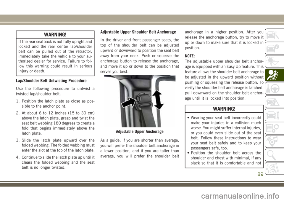
Adjustable Upper Shoulder Belt Anchorage
In the driver and front passenger seats, the
top of the shoulder belt can be adjusted
upward or downward to position the seat belt
away from your neck. Push or squeeze the
anchorage button to release the anchorage,
and move it up or down to the position that
serves you best.
As a guide, if you are shorter than average,
you will prefer the shoulder belt anchorage in
a lower position, and if you are taller than
average, you will prefer the shoulder beltanchorage in a higher position. After you
release the anchorage button, try to move it
up or down to make sure that it is locked in
position.
NOTE:
The adjustable upper shoulder belt anchor-
age is equipped with an Easy Up feature. This
feature allows the shoulder belt anchorage to
be adjusted in the upward position without
pushing or squeezing the release button. To
verify the shoulder belt anchorage is latched,
pull downward on the shoulder belt anchor-
age until it is locked into position.
WARNING!
• Wearing your seat belt incorrectly could
make your injuries in a collision much
worse. You might suffer internal injuries,
or you could even slide out of the seat
belt. Follow these instructions to wear
your seat belt safely and to keep your
passengers safe, too.
• Position the shoulder belt across the
shoulder and chest with minimal, if any
slack so that it is comfortable and not
Adjustable Upper Anchorage
89