lock JEEP WRANGLER 2021 Owner handbook (in English)
[x] Cancel search | Manufacturer: JEEP, Model Year: 2021, Model line: WRANGLER, Model: JEEP WRANGLER 2021Pages: 276, PDF Size: 4.47 MB
Page 156 of 276
JACKING AND TIRE
CHANGING
WARNING!
• Do not attempt to change a tire on the
side of the vehicle close to moving traf-
fic. Pull far enough off the road to avoid
the danger of being hit when operating
the jack or changing the wheel.
• Being under a jacked-up vehicle is dan-
gerous. The vehicle could slip off the
jack and fall on you. You could be
crushed. Never put any part of your body
under a vehicle that is on a jack. If you
need to get under a raised vehicle, take
it to a service center where it can be
raised on a lift.
• Never start or run the engine while the
vehicle is on a jack.
• The jack is designed to be used as a tool
for changing tires only. The jack should
not be used to lift the vehicle for service
purposes. The vehicle should be jacked
on a firm level surface only. Avoid ice or
slippery areas.
Jack/Spare Tire Stowage
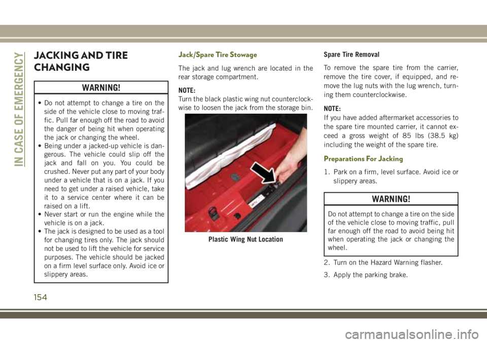
The jack and lug wrench are located in the
rear storage compartment.
NOTE:
Turn the black plastic wing nut counterclock-
wise to loosen the jack from the storage bin.Spare Tire Removal
To remove the spare tire from the carrier,
remove the tire cover, if equipped, and re-
move the lug nuts with the lug wrench, turn-
ing them counterclockwise.
NOTE:
If you have added aftermarket accessories to
the spare tire mounted carrier, it cannot ex-
ceed a gross weight of 85 lbs (38.5 kg)
including the weight of the spare tire.
Preparations For Jacking
1. Park on a firm, level surface. Avoid ice or
slippery areas.
WARNING!
Do not attempt to change a tire on the side
of the vehicle close to moving traffic, pull
far enough off the road to avoid being hit
when operating the jack or changing the
wheel.
2. Turn on the Hazard Warning flasher.
3. Apply the parking brake.
Plastic Wing Nut Location
IN CASE OF EMERGENCY
154
Page 157 of 276
4. Shift the automatic transmission into
PARK, or a manual transmission into
REVERSE.
5. Turn the ignition to LOCK.
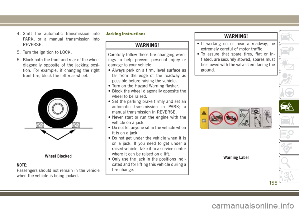
6. Block both the front and rear of the wheel
diagonally opposite of the jacking posi-
tion. For example, if changing the right
front tire, block the left rear wheel.
NOTE:
Passengers should not remain in the vehicle
when the vehicle is being jacked.Jacking Instructions
WARNING!
Carefully follow these tire changing warn-
ings to help prevent personal injury or
damage to your vehicle:
• Always park on a firm, level surface as
far from the edge of the roadway as
possible before raising the vehicle.
• Turn on the Hazard Warning flasher.
• Block the wheel diagonally opposite the
wheel to be raised.
• Set the parking brake firmly and set an
automatic transmission in PARK; a
manual transmission in REVERSE.
• Never start or run the engine with the
vehicle on a jack.
• Do not let anyone sit in the vehicle when
it is on a jack.
• Do not get under the vehicle when it is
on a jack. If you need to get under a
raised vehicle, take it to a service center
where it can be raised on a lift.
• Only use the jack in the positions indi-
cated and for lifting this vehicle during a
tire change.
WARNING!
• If working on or near a roadway, be
extremely careful of motor traffic.
• To assure that spare tires, flat or in-
flated, are securely stowed, spares must
be stowed with the valve stem facing the
ground.
Wheel BlockedWarning Label
155
Page 158 of 276
CAUTION!
Do not attempt to raise the vehicle by
jacking on locations other than those indi-
cated.
1. Remove the spare tire, jack and tools from
the stored location.
2. Loosen (but do not remove) the wheel lug
nuts by turning them to the left one turn
while the wheel is still on the ground.
3. Assemble the jack and jacking tools. Con-
nect the jack handle driver to the exten-
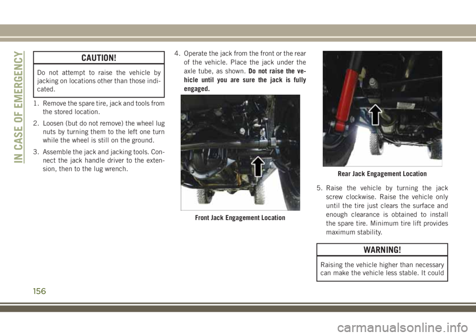
sion, then to the lug wrench.4. Operate the jack from the front or the rear
of the vehicle. Place the jack under the
axle tube, as shown.Do not raise the ve-
hicle until you are sure the jack is fully
engaged.
5. Raise the vehicle by turning the jack
screw clockwise. Raise the vehicle only
until the tire just clears the surface and
enough clearance is obtained to install
the spare tire. Minimum tire lift provides
maximum stability.
WARNING!
Raising the vehicle higher than necessary
can make the vehicle less stable. It could
Front Jack Engagement Location
Rear Jack Engagement Location
IN CASE OF EMERGENCY
156
Page 159 of 276
WARNING!
slip off the jack and hurt someone near it.
Raise the vehicle only enough to remove
the tire.
6. Remove the lug nuts and wheel.
7. Position the spare wheel/tire on the ve-
hicle and install the lug nuts with the
cone-shaped end toward the wheel.
Lightly tighten the lug nuts clockwise.
WARNING!
To avoid the risk of forcing the vehicle off
the jack, do not tighten the wheel nuts
fully until the vehicle has been lowered.
Failure to follow this warning may result in
serious injury.
8. Lower the vehicle by turning the jack
screw to the left, and remove the jack.9. Finish tightening the lug nuts. Push down
on the wrench while tightening for in-
creased leverage. Alternate nuts until
each nut has been tightened twice. Refer
to “Torque Specifications” in “Technical
Specifications” for correct lug nut torque.
10. Remove the jack assembly and wheel
blocks.
11. Secure the tire, jack, and tools in their
proper locations.
WARNING!
A loose tire or jack thrown forward in a
collision or hard stop, could endanger the
occupants of the vehicle. Always stow the
jack parts and the spare tire in the places
provided.
Declaration Of Conformance
1. The undersigned, Tony Fabiano, repre-
senting the manufacturer, herewith de-
clares that the machinery described below
fulfills all relevant provisions of:
• The EC-directive 2006/42/EC on
Machinery
2. Description of machinery.
a) Generic Denomination: Vehicle Jack
b) Function: Lifting Vehicle
d) Ve-
hicle
Modelc) Model
Codef) Work-
ing Loade) Jack
Type
Jeep
®
CompassMK 1200 kg
MaxFGMF1
Jeep
CherokeeKL 1000 kg
MaxFGLF1
Jeep
WranglerJK 1000 kg
MaxFGLF2
Jeep
Grand
CherokeeWK 1700 kg
MaxFGLF3
157
Page 163 of 276
CAUTION!
voltage greater than 12 Volts or damage to
the battery, starter motor, alternator or
electrical system may occur.
NOTE:
When using a portable battery booster pack,
follow the manufacturer's operating instruc-
tions and precautions.
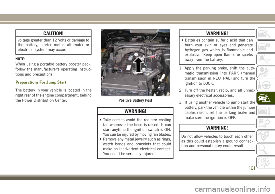
Preparations For Jump Start
The battery in your vehicle is located in the
right rear of the engine compartment, behind
the Power Distribution Center.
WARNING!
• Take care to avoid the radiator cooling
fan whenever the hood is raised. It can
start anytime the ignition switch is ON.
You can be injured by moving fan blades.
• Remove any metal jewelry such as rings,
watch bands and bracelets that could
make an inadvertent electrical contact.
You could be seriously injured.
WARNING!
• Batteries contain sulfuric acid that can
burn your skin or eyes and generate
hydrogen gas which is flammable and
explosive. Keep open flames or sparks
away from the battery.
1. Apply the parking brake, shift the auto-
matic transmission into PARK (manual
transmission in NEUTRAL) and turn the
ignition to LOCK.
2. Turn off the heater, radio, and all unnec-
essary electrical accessories.
3. If using another vehicle to jump start the
battery, park the vehicle within the jumper
cables reach, set the parking brake and
make sure the ignition is OFF.
WARNING!
Do not allow vehicles to touch each other
as this could establish a ground connec-
tion and personal injury could result.
Positive Battery Post
161
Page 168 of 276
Wheel Lift Or Dolly TowFrontNOT ALLOWED
RearNOT ALLOWED
FlatbedALL BEST METHOD
Proper towing or lifting equipment is required
to prevent damage to your vehicle. Use only
tow bars and other equipment designed for
this purpose, following equipment manufac-
turer’s instructions. Use of safety chains is
mandatory. Attach a tow bar or other towing
device to main structural members of the
vehicle, not to bumpers or associated brack-
ets. State and local laws regarding vehicles
under tow must be observed.
If you must use the accessories (wipers, de-
frosters, etc.) while being towed, the ignition
must be in the ON/RUN position, not the ACC
position.
If the vehicle's battery is discharged, refer to
“Gear Selector Override” in this section for
instructions on shifting the automatic trans-
mission out of PARK for towing.CAUTION!
• Do not use sling type equipment when
towing. Vehicle damage may occur.
• When securing the vehicle to a flatbed
truck, do not attach to front or rear
suspension components. Damage to
your vehicle may result from improper
towing.
• If the vehicle being towed requires steer-
ing, the ignition switch must be in the
ACC or ON/RUN mode, not in the LOCK/
OFF mode.
Without The Ignition Key
Special care must be taken when the vehicle
is towed with the ignition in the LOCK posi-
tion. The only approved method of towing
without the ignition key is with a flatbed
truck. Proper towing equipment is necessary
to prevent damage to the vehicle.
Four–Wheel Drive Models
The manufacturer recommends towing with
all wheelsOFFthe ground. Acceptable meth-
ods are to tow the vehicle on a flatbed or with
one end of the vehicle raised and the oppo-
site end on a towing dolly.
If flatbed equipment is not available and the
transfer case is operable, the vehicle may be
towed (in the forward direction, withALL
wheels on the ground),IFthe transfer case is
inNEUTRAL(N) and the transmission is in
PARK(for automatic transmissions) or in gear
(NOTinNEUTRAL, for manual transmissions).
Refer to “Recreational Towing” in “Starting
And Operating” for detailed instructions.
CAUTION!
• Front or rear wheel lifts must not be used
(if the remaining wheels are on the
ground). Internal damage to the trans-
IN CASE OF EMERGENCY
166
Page 192 of 276
• Hardening Or Cracking
• Deformation Or Fatigue
If a wiper blade or wiper arm is damaged,
replace the affected wiper arm or blade with
a new unit. Do not attempt to repair a wiper
arm or blade that is damaged.
Wiper Blade Removal/Installation
CAUTION!
Do not allow the wiper arm to spring back
against the glass without the wiper blade
in place or the glass may be damaged.
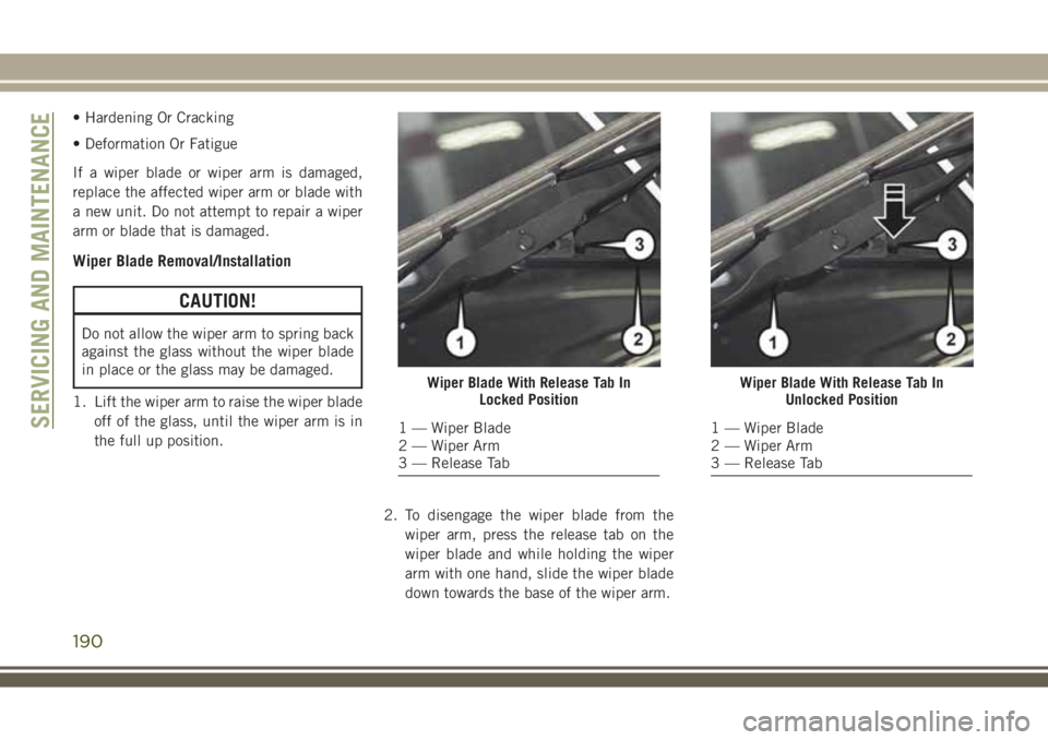
1. Lift the wiper arm to raise the wiper blade
off of the glass, until the wiper arm is in
the full up position.
2. To disengage the wiper blade from the
wiper arm, press the release tab on the
wiper blade and while holding the wiper
arm with one hand, slide the wiper blade
down towards the base of the wiper arm.
Wiper Blade With Release Tab In
Locked Position
1 — Wiper Blade
2 — Wiper Arm
3 — Release Tab
Wiper Blade With Release Tab In
Unlocked Position
1 — Wiper Blade
2 — Wiper Arm
3 — Release TabSERVICING AND MAINTENANCE
190
Page 210 of 276
VEHICLE IDENTIFICATION
NUMBER
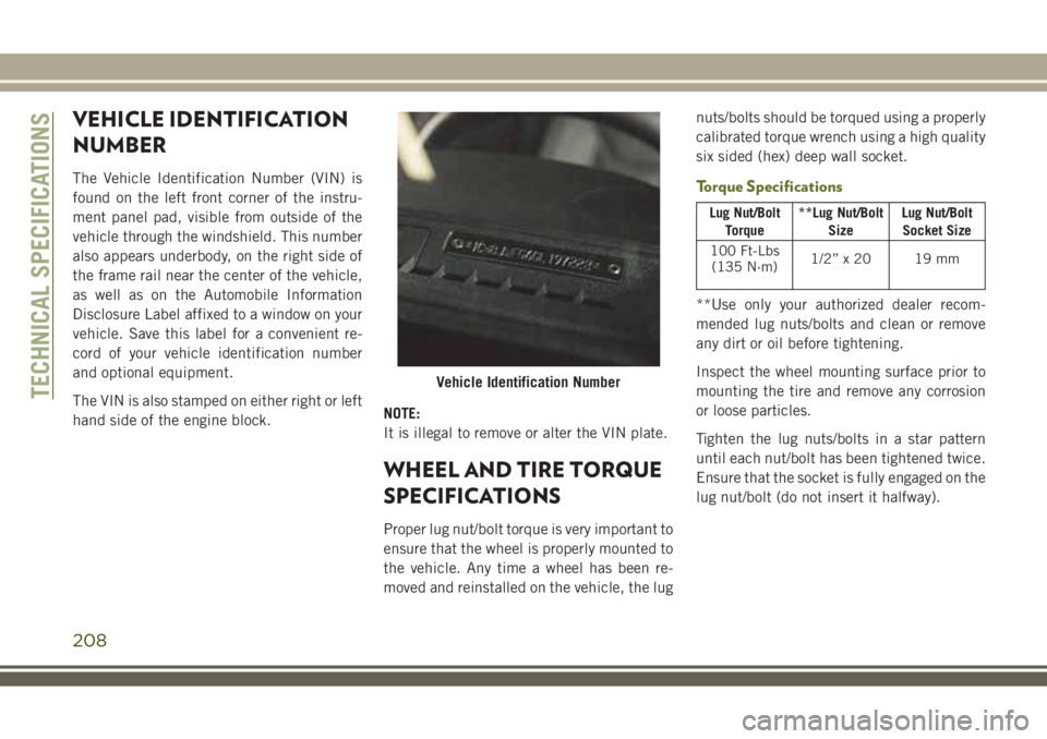
The Vehicle Identification Number (VIN) is
found on the left front corner of the instru-
ment panel pad, visible from outside of the
vehicle through the windshield. This number
also appears underbody, on the right side of
the frame rail near the center of the vehicle,
as well as on the Automobile Information
Disclosure Label affixed to a window on your
vehicle. Save this label for a convenient re-
cord of your vehicle identification number
and optional equipment.
The VIN is also stamped on either right or left
hand side of the engine block.NOTE:
It is illegal to remove or alter the VIN plate.
WHEEL AND TIRE TORQUE
SPECIFICATIONS
Proper lug nut/bolt torque is very important to
ensure that the wheel is properly mounted to
the vehicle. Any time a wheel has been re-
moved and reinstalled on the vehicle, the lugnuts/bolts should be torqued using a properly
calibrated torque wrench using a high quality
six sided (hex) deep wall socket.
Torque Specifications
Lug Nut/Bolt
Torque**Lug Nut/Bolt
SizeLug Nut/Bolt
Socket Size
100 Ft-Lbs
(135 N·m)1/2” x 20 19 mm
**Use only your authorized dealer recom-
mended lug nuts/bolts and clean or remove
any dirt or oil before tightening.
Inspect the wheel mounting surface prior to
mounting the tire and remove any corrosion
or loose particles.
Tighten the lug nuts/bolts in a star pattern
until each nut/bolt has been tightened twice.
Ensure that the socket is fully engaged on the
lug nut/bolt (do not insert it halfway).
Vehicle Identification NumberTECHNICAL SPECIFICATIONS
208
Page 215 of 276
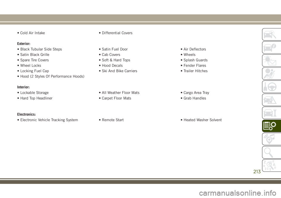
• Cold Air Intake • Differential Covers
Exterior:
• Black Tubular Side Steps • Satin Fuel Door • Air Deflectors
• Satin Black Grille • Cab Covers • Wheels
• Spare Tire Covers • Soft & Hard Tops • Splash Guards
• Wheel Locks • Hood Decals • Fender Flares
• Locking Fuel Cap • Ski And Bike Carriers • Trailer Hitches
• Hood (2 Styles Of Performance Hoods)
Interior:
• Lockable Storage • All Weather Floor Mats • Cargo Area Tray
• Hard Top Headliner • Carpet Floor Mats • Grab Handles
Electronics:
• Electronic Vehicle Tracking System • Remote Start • Heated Washer Solvent
213
Page 217 of 276
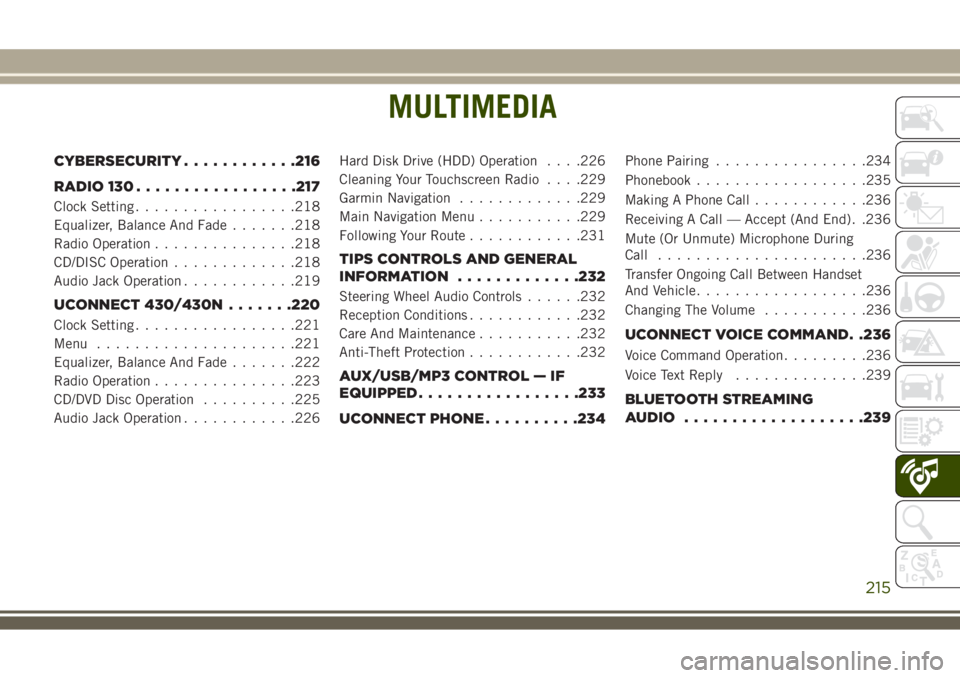
MULTIMEDIA
CYBERSECURITY............216
RADIO 130.................217
Clock Setting.................218
Equalizer, Balance And Fade.......218
Radio Operation...............218
CD/DISC Operation.............218
Audio Jack Operation............219
UCONNECT 430/430N.......220
Clock Setting.................221
Menu.....................221
Equalizer, Balance And Fade.......222
Radio Operation...............223
CD/DVD Disc Operation..........225
Audio Jack Operation............226Hard Disk Drive (HDD) Operation. . . .226
Cleaning Your Touchscreen Radio. . . .229
Garmin Navigation.............229
Main Navigation Menu...........229
Following Your Route............231
TIPS CONTROLS AND GENERAL
INFORMATION.............232
Steering Wheel Audio Controls......232
Reception Conditions............232
Care And Maintenance...........232
Anti-Theft Protection............232
AUX/USB/MP3 CONTROL — IF
EQUIPPED.................233
UCONNECT PHONE..........234
Phone Pairing................234
Phonebook..................235
Making A Phone Call............236
Receiving A Call — Accept (And End). .236
Mute (Or Unmute) Microphone During
Call......................236
Transfer Ongoing Call Between Handset
And Vehicle..................236
Changing The Volume...........236
UCONNECT VOICE COMMAND. .236
Voice Command Operation.........236
Voice Text Reply..............239
BLUETOOTH STREAMING
AUDIO...................239
MULTIMEDIA
215