lock JEEP WRANGLER 2021 Owner handbook (in English)
[x] Cancel search | Manufacturer: JEEP, Model Year: 2021, Model line: WRANGLER, Model: JEEP WRANGLER 2021Pages: 276, PDF Size: 4.47 MB
Page 135 of 276
To activate the system, push the bottom of
the AXLE LOCK switch once to lock the rear
axle only (the “Rear Axle Lock Indicator
Light” will illuminate), push the bottom of
the switch again to lock the front axle (the
“Front Axle Lock Indicator Light” will illumi-
nate). When the rear axle is locked, pushing
the bottom of switch again will lock or unlock
the front axle.
NOTE:
The indicator lights will flash until the axles
are fully locked or unlocked.
To unlock the axles, push the top of the AXLE
LOCK switch.
Axle lock will disengage if the vehicle is taken
out of 4L (Low) range, or the ignition switch is
turned to the OFF position.
Electronic Sway Bar Disconnect — If
Equipped
Your vehicle may be equipped with an elec-
tronic disconnecting stabilizer/sway bar. This
system allows greater front suspension travel
in off-road situations.This system is controlled by the SWAY BAR
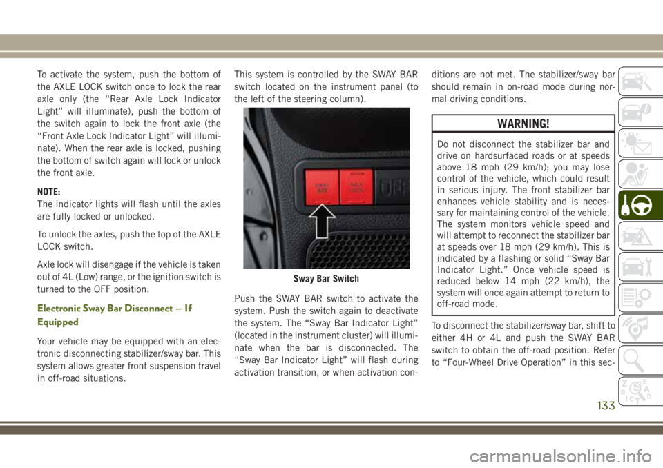
switch located on the instrument panel (to
the left of the steering column).
Push the SWAY BAR switch to activate the
system. Push the switch again to deactivate
the system. The “Sway Bar Indicator Light”
(located in the instrument cluster) will illumi-
nate when the bar is disconnected. The
“Sway Bar Indicator Light” will flash during
activation transition, or when activation con-ditions are not met. The stabilizer/sway bar
should remain in on-road mode during nor-
mal driving conditions.
WARNING!
Do not disconnect the stabilizer bar and
drive on hardsurfaced roads or at speeds
above 18 mph (29 km/h); you may lose
control of the vehicle, which could result
in serious injury. The front stabilizer bar
enhances vehicle stability and is neces-
sary for maintaining control of the vehicle.
The system monitors vehicle speed and
will attempt to reconnect the stabilizer bar
at speeds over 18 mph (29 km/h). This is
indicated by a flashing or solid “Sway Bar
Indicator Light.” Once vehicle speed is
reduced below 14 mph (22 km/h), the
system will once again attempt to return to
off-road mode.
To disconnect the stabilizer/sway bar, shift to
either 4H or 4L and push the SWAY BAR
switch to obtain the off-road position. Refer
to “Four-Wheel Drive Operation” in this sec-
Sway Bar Switch
133
Page 136 of 276
tion for further information. The “Sway Bar
Indicator Light” will flash until the stabilizer/
sway bar has been fully disconnected.
NOTE:
The stabilizer/sway bar may be torque locked
due to left and right suspension height differ-
ences. This condition is due to driving sur-
face differences or vehicle loading. In order
for the stabilizer/sway bar to disconnect/
reconnect, the right and left halves of the bar
must be aligned. This alignment may require
that the vehicle be driven onto level ground or
rocked from side to side.
To return to on-road mode, push the SWAY
BAR switch again.
WARNING!
If the stabilizer/sway bar will not return to
on-road mode, the “Sway Bar Indicator
Light” will flash in the instrument cluster
and vehicle stability is greatly reduced. Do
not attempt to drive the vehicle over
18 mph (29 km/h). Driving faster than
18 mph (29 km/ h) may cause loss of
control of the vehicle, which could result
WARNING!
in serious injury. Contact your local autho-
rized dealer for assistance.
STOP/START SYSTEM —
DIESEL MODELS WITH
MANUAL TRANSMISSION
ONLY
The Stop/Start function is developed to save
fuel and reduce emissions. The system will
stop the engine automatically during a ve-
hicle stop if the required conditions are met.
Pressing the clutch pedal will automatically
restart the vehicle.
Automatic Mode
The Stop/Start feature is en-
abled after every normal cus-
tomer engine start. It will remain
in STOP/START NOT READY un-
til you drive forward with a ve-
hicle speed greater than 3 mph (5 km/h). Atthat time, the system will go into STOP/
START READY and if all other conditions are
met, can go into an STOP/START AUTO STOP
ACTIVE mode.
To Activate The STOP/START AUTO STOP ACTIVE
Mode, The Following Must Occur:
• The system must be in STOP/START
READY state. A STOP/START READY mes-
sage will be displayed in the instrument
cluster. Refer to “Instrument Cluster Dis-
play” in “Getting To Know Your Instrument
Panel” for further information.
• Vehicle speed must be less 3 mph (5 km/h).
• The gear selector must be in the NEUTRAL
position and the clutch pedal must be fully
released
The engine will shut down,the tachometer will
fall to the Stop/Start position,the STOP/START
AUTO STOP ACTIVE message will appear,
and the heater/air conditioning (HVAC) air
flow will be reduced.
STARTING AND OPERATING
134
Page 145 of 276
CAUTION!
• Automatic transmissions must be
placed in PARK for recreational towing.
• Manual transmissions must be placed in
gear (not in Neutral) for recreational
towing.
• Before recreational towing, perform the
procedure outlined under “Shifting Into
NEUTRAL (N)” to be certain that the
transfer case is fully in NEUTRAL (N).
Otherwise, internal damage will result.
• Towing this vehicle in violation of the
above requirements can cause severe
transmission and/or transfer case dam-
age. Damage from improper towing is
not covered under the New Vehicle Lim-
ited Warranty.
• Do not use a bumper-mounted clamp-on
tow bar on your vehicle. The bumper
face bar will be damaged.
Shifting Into NEUTRAL (N)
Use the following procedure to prepare your
vehicle for recreational towing.
WARNING!
You or others could be injured or killed if
you leave the vehicle unattended with the
transfer case in the NEUTRAL (N) position
without first fully engaging the parking
brake. The transfer case NEUTRAL (N)
position disengages both the front and rear
driveshafts from the powertrain, and will
allow the vehicle to roll, even if the auto-
matic transmission is in PARK (or manual
transmission is in gear). The parking brake
should always be applied when the driver
is not in the vehicle.
CAUTION!
It is necessary to follow these steps to be
certain that the transfer case is fully in
NEUTRAL (N) before recreational towing
to prevent damage to internal parts.
1. Bring the vehicle to a complete stop on
level ground.
2. Press and hold the brake pedal.3. Shift the automatic transmission into
NEUTRAL or depress the clutch pedal on
a manual transmission.
4. Turn the engine OFF.
5. Shift the transfer case lever into NEU-
TRAL (N).
6. Start the engine.
7. Shift the transmission into REVERSE.
8. Release the brake pedal (and clutch pedal
on manual transmissions) for five seconds
and ensure that there is no vehicle
movement.
9. Repeat steps seven and eight with auto-
matic transmission in DRIVE or manual
transmission in first gear.
10. Turn the engine OFF and leave the igni-
tion in the unlocked ACC position.
11. Firmly apply the parking brake.
12. Shift the transmission into PARK or
place manual transmission in gear (NOT
in NEUTRAL).
143
Page 146 of 276
CAUTION!
Damage to the transmission may occur if
the transmission is shifted into PARK with
the transfer case in NEUTRAL (N) and the
engine running. With the transfer case in
NEUTRAL (N) ensure that the engine is
OFF before shifting the transmission into
PARK.
13. Attach the vehicle to the tow vehicle
using a suitable tow bar.
14. Release the parking brake.
15. Disconnect the negative battery cable,
and secure it away from the negative
battery post.
Shifting Out of NEUTRAL (N)
Use the following procedure to prepare your
vehicle for normal usage.
1. Bring the vehicle to a complete stop,
leaving it connected to the tow vehicle.
2. Firmly apply the parking brake.
3. Reconnect the negative battery cable.
4. Turn the ignition to the LOCK position.
5. Turn the ignition to the ON/RUN position,
but do not start the engine.
6. Press and hold the brake pedal.
7. Shift the transmission into NEUTRAL.8. Shift the transfer case lever to the desired
position.
NOTE:
When shifting the transfer case out of
NEUTRAL (N), the engine should remain
OFF to avoid gear clash.
9. Shift the automatic transmission into
PARK, or place manual transmission in
NEUTRAL.
10. Release the brake pedal.
11. Disconnect vehicle from the tow vehicle.
12. Start the engine.
13. Press and hold the brake pedal.
14. Release the parking brake.
15. Shift the transmission into gear, release
the brake pedal (and clutch pedal on
manual transmissions), and check that
the vehicle operates normally.
STARTING AND OPERATING
144
Page 149 of 276
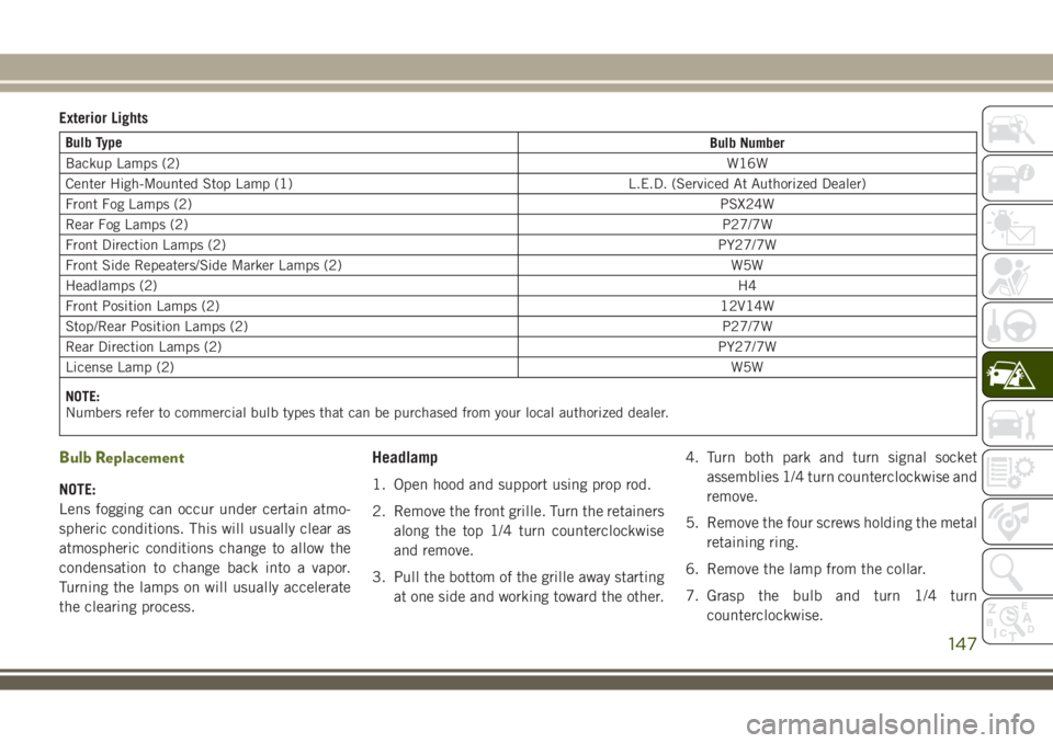
Exterior Lights
Bulb Type
Bulb Number
Backup Lamps (2)W16W
Center High-Mounted Stop Lamp (1) L.E.D. (Serviced At Authorized Dealer)
Front Fog Lamps (2)PSX24W
Rear Fog Lamps (2)P27/7W
Front Direction Lamps (2)PY27/7W
Front Side Repeaters/Side Marker Lamps (2) W5W
Headlamps (2)H4
Front Position Lamps (2)12V14W
Stop/Rear Position Lamps (2)P27/7W
Rear Direction Lamps (2)PY27/7W
License Lamp (2)W5W
NOTE:
Numbers refer to commercial bulb types that can be purchased from your local authorized dealer.
Bulb Replacement
NOTE:
Lens fogging can occur under certain atmo-
spheric conditions. This will usually clear as
atmospheric conditions change to allow the
condensation to change back into a vapor.
Turning the lamps on will usually accelerate
the clearing process.
Headlamp
1. Open hood and support using prop rod.
2. Remove the front grille. Turn the retainers
along the top 1/4 turn counterclockwise
and remove.
3. Pull the bottom of the grille away starting
at one side and working toward the other.4. Turn both park and turn signal socket
assemblies 1/4 turn counterclockwise and
remove.
5. Remove the four screws holding the metal
retaining ring.
6. Remove the lamp from the collar.
7. Grasp the bulb and turn 1/4 turn
counterclockwise.
147
Page 150 of 276
8. Pull the bulb from the housing.
9. Push connector locking tab to the unlock
position.
10. Remove connector from bulb.
11. Push connector onto new bulb base, and
push the connector locking tab to the
lock position.
CAUTION!
Do not touch the new bulb with your fin-
gers. Oil contamination will severely
shorten bulb life. If the bulb comes in
contact with any oily surface, clean the
bulb with rubbing alcohol.
12. Reinstall bulb housing. Rotate the bulb
1/4 turn clockwise.
Front Park/Turn Signal
1. Remove the front grille. Turn the retainers
along the top 1/4 turn counterclockwise
and remove.
2. Pull the bottom of the grille away starting
at one side and working toward the other.3. Turn the socket assembly 1/4 turn coun-
terclockwise and remove from housing.
Pull the bulb straight from the socket to
replace.
Front Side Marker
1. Reach under the front fender flare and
locate the front side marker socket.
2. Turn the socket assembly counterclock-
wise 1/3 turn and remove it from the
housing. Pull the bulb straight from the
socket to replace.
Front Fog Lamp
1. Reach under the vehicle to access the
back of the front fog lamp.
2. Disconnect the wire harness connector
from the front fog lamp connector
receptacle.
3. Firmly grasp the bulb by the two latch
features and squeeze them together to
unlock the bulb from the back of the front
fog lamp housing.4. Pull the bulb straight out from the keyed
opening in the housing and then connect
the replacement bulb.
CAUTION!
Do not touch the new bulb with your fin-
gers. Oil contamination will severely
shorten bulb life. If the bulb comes in
contact with any oily surface, clean the
bulb with rubbing alcohol.
Rear Fog Lamp
1. Reach under the vehicle to access the
back of the rear fog lamp.
2. Turn the socket assembly counterclock-
wise 1/4 turn and remove it from the
housing. Pull the bulb straight from the
socket to replace.IN CASE OF EMERGENCY
148
Page 151 of 276
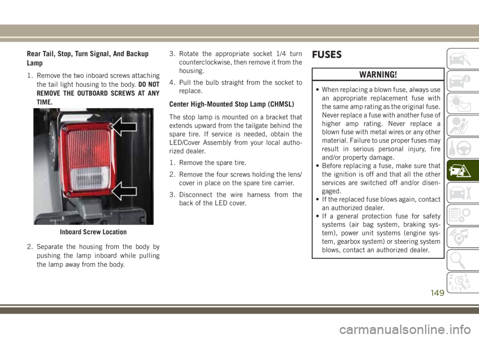
Rear Tail, Stop, Turn Signal, And Backup
Lamp
1. Remove the two inboard screws attaching
the tail light housing to the body.DO NOT
REMOVE THE OUTBOARD SCREWS AT ANY
TIME.
2. Separate the housing from the body by
pushing the lamp inboard while pulling
the lamp away from the body.3. Rotate the appropriate socket 1/4 turn
counterclockwise, then remove it from the
housing.
4. Pull the bulb straight from the socket to
replace.
Center High-Mounted Stop Lamp (CHMSL)
The stop lamp is mounted on a bracket that
extends upward from the tailgate behind the
spare tire. If service is needed, obtain the
LED/Cover Assembly from your local autho-
rized dealer.
1. Remove the spare tire.
2. Remove the four screws holding the lens/
cover in place on the spare tire carrier.
3. Disconnect the wire harness from the
back of the LED cover.
FUSES
WARNING!
• When replacing a blown fuse, always use
an appropriate replacement fuse with
the same amp rating as the original fuse.
Never replace a fuse with another fuse of
higher amp rating. Never replace a
blown fuse with metal wires or any other
material. Failure to use proper fuses may
result in serious personal injury, fire
and/or property damage.
• Before replacing a fuse, make sure that
the ignition is off and that all the other
services are switched off and/or disen-
gaged.
• If the replaced fuse blows again, contact
an authorized dealer.
• If a general protection fuse for safety
systems (air bag system, braking sys-
tem), power unit systems (engine sys-
tem, gearbox system) or steering system
blows, contact an authorized dealer.
Inboard Screw Location
149
Page 152 of 276
General Information
The fuses protect electrical systems against
excessive current.
When a device does not work, you must check
the fuse element inside the blade fuse for a
break/melt.
Also, please be aware that when using power
outlets for extended periods of time with the
engine off may result in vehicle battery dis-
charge.
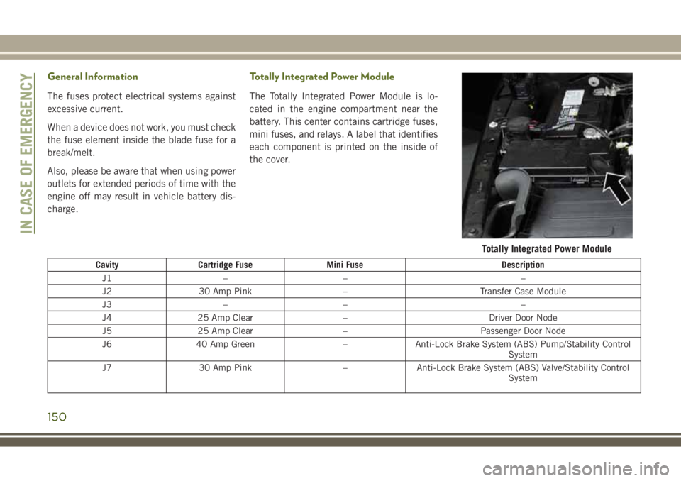
Totally Integrated Power Module
The Totally Integrated Power Module is lo-
cated in the engine compartment near the
battery. This center contains cartridge fuses,
mini fuses, and relays. A label that identifies
each component is printed on the inside of
the cover.
Cavity Cartridge Fuse Mini Fuse Description
J1 – – –
J2 30 Amp Pink – Transfer Case Module
J3 – – –
J4 25 Amp Clear – Driver Door Node
J5 25 Amp Clear – Passenger Door Node
J6 40 Amp Green – Anti-Lock Brake System (ABS) Pump/Stability Control
System
J7 30 Amp Pink – Anti-Lock Brake System (ABS) Valve/Stability Control
System
Totally Integrated Power Module
IN CASE OF EMERGENCY
150
Page 153 of 276
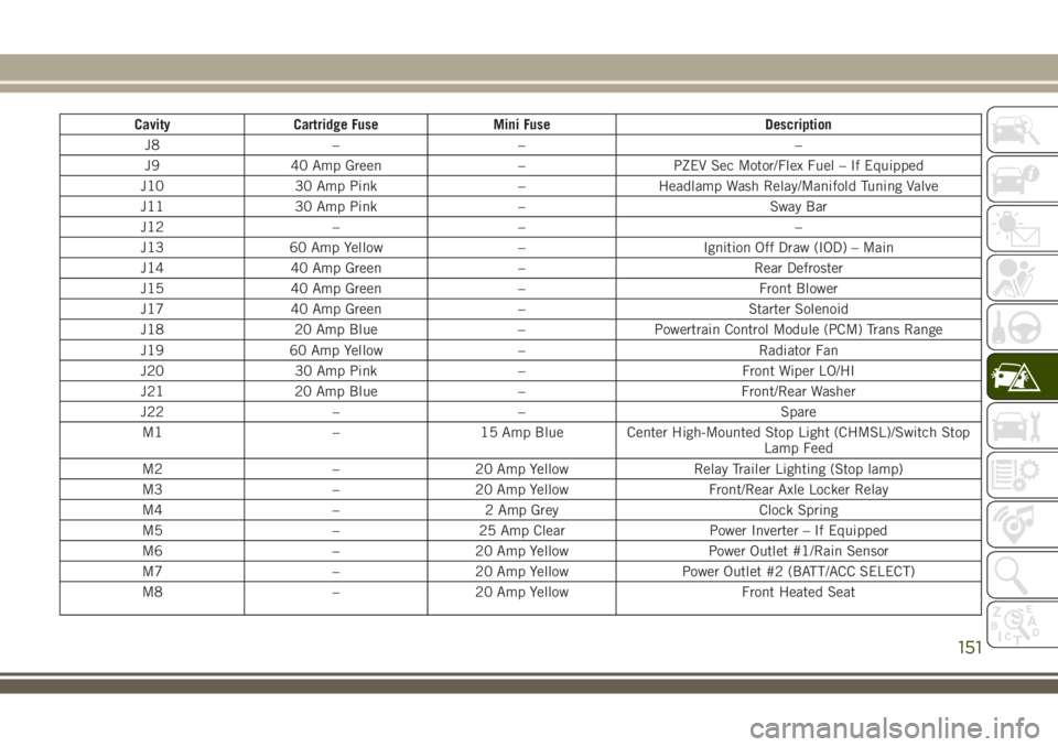
Cavity Cartridge Fuse Mini Fuse Description
J8 – – –
J9 40 Amp Green – PZEV Sec Motor/Flex Fuel – If Equipped
J10 30 Amp Pink – Headlamp Wash Relay/Manifold Tuning Valve
J11 30 Amp Pink – Sway Bar
J12 – – –
J13 60 Amp Yellow – Ignition Off Draw (IOD) – Main
J14 40 Amp Green – Rear Defroster
J15 40 Amp Green – Front Blower
J17 40 Amp Green – Starter Solenoid
J18 20 Amp Blue – Powertrain Control Module (PCM) Trans Range
J19 60 Amp Yellow – Radiator Fan
J20 30 Amp Pink – Front Wiper LO/HI
J21 20 Amp Blue – Front/Rear Washer
J22 – – Spare
M1 – 15 Amp Blue Center High-Mounted Stop Light (CHMSL)/Switch Stop
Lamp Feed
M2 – 20 Amp Yellow Relay Trailer Lighting (Stop lamp)
M3 – 20 Amp Yellow Front/Rear Axle Locker Relay
M4 – 2 Amp Grey Clock Spring
M5 – 25 Amp Clear Power Inverter – If Equipped
M6 – 20 Amp Yellow Power Outlet #1/Rain Sensor
M7 – 20 Amp Yellow Power Outlet #2 (BATT/ACC SELECT)
M8 – 20 Amp Yellow Front Heated Seat
151
Page 155 of 276
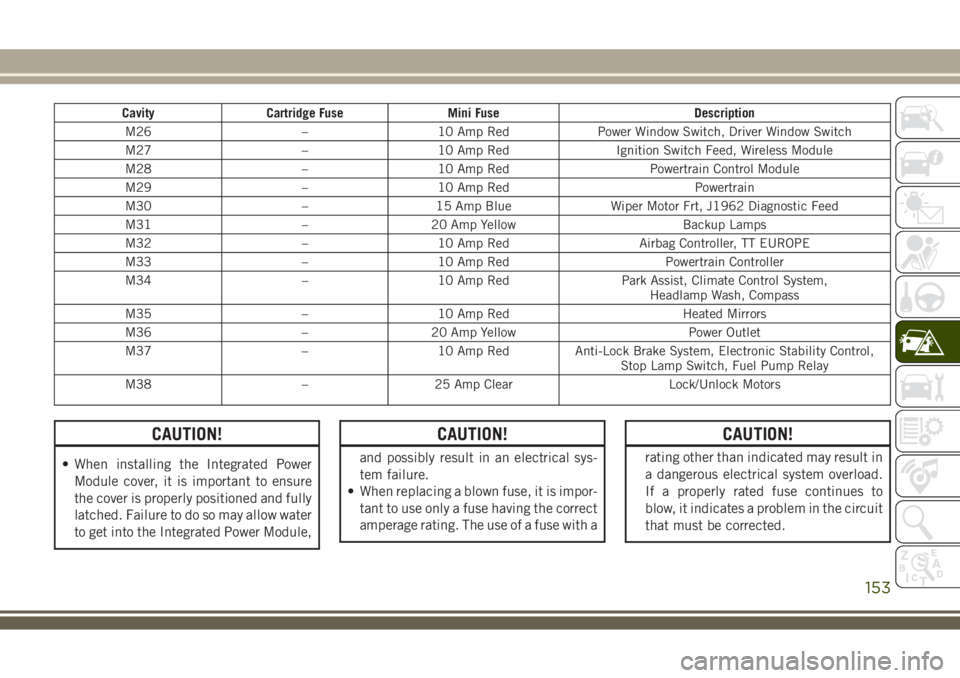
Cavity Cartridge Fuse Mini Fuse Description
M26 – 10 Amp Red Power Window Switch, Driver Window Switch
M27 – 10 Amp Red Ignition Switch Feed, Wireless Module
M28 – 10 Amp Red Powertrain Control Module
M29 – 10 Amp Red Powertrain
M30 – 15 Amp Blue Wiper Motor Frt, J1962 Diagnostic Feed
M31 – 20 Amp Yellow Backup Lamps
M32 – 10 Amp Red Airbag Controller, TT EUROPE
M33 – 10 Amp Red Powertrain Controller
M34 – 10 Amp Red Park Assist, Climate Control System,
Headlamp Wash, Compass
M35 – 10 Amp Red Heated Mirrors
M36 – 20 Amp Yellow Power Outlet
M37 – 10 Amp Red Anti-Lock Brake System, Electronic Stability Control,
Stop Lamp Switch, Fuel Pump Relay
M38 – 25 Amp Clear Lock/Unlock Motors
CAUTION!
• When installing the Integrated Power
Module cover, it is important to ensure
the cover is properly positioned and fully
latched. Failure to do so may allow water
to get into the Integrated Power Module,
CAUTION!
and possibly result in an electrical sys-
tem failure.
• When replacing a blown fuse, it is impor-
tant to use only a fuse having the correct
amperage rating. The use of a fuse with a
CAUTION!
rating other than indicated may result in
a dangerous electrical system overload.
If a properly rated fuse continues to
blow, it indicates a problem in the circuit
that must be corrected.
153